O R I G I N A L R E S E A R C H
Open Access
Direct torque control of doubly fed
induction motor using three-level NPC
inverter
Najib El Ouanjli
1*, Aziz Derouich
1, Abdelaziz El Ghzizal
1, Mohammed Taoussi
2, Youness El Mourabit
1,
Khalid Mezioui
3and Badre Bossoufi
2Abstract
This article presents the direct torque control (DTC) strategy for the doubly fed induction motor (DFIM) connected to two three-level voltage source inverters (3LVSIs) with neutral point clamped (NPC) structure. This control method allows to reduce the torque and flux ripples as well as to optimize the total harmonic distortion (THD) of motor currents. The use of 3LVSI increases the number of generated voltage, which allows improving the quality of its waveform and thus improves the DTC strategy. The system modeling and control are implemented in Matlab/ Simulink environment. The analysis of simulation results shows the better performances of this control, especially in terms of torque and flux behavior, compared to conventional DTC.
Keywords:Direct torque control, Doubly fed induction motor, Three-level inverter, Ripples, Switching table
1 Introduction
In the mid−1980s, the direct torque control strategy of induction machine was introduced by Takahashi to overcome the problems of conventional controls such as scalar control (SC) and field oriented control (FOC) [1, 2]. DTC is based on the direct regulation of electromagnetic torque and flux of the machine.
This control is characterized by good torque
dynamic response, high robustness and less complex-ity than other controls [3]. It allows minimizing the influence of parametric variations in the machine and calculating the control variables which are stator flux and electromagnetic torque from the stator current measurements without using mechanical speed sensors [4].
Recently, many authors have applied the DTC tech-nique to the Doubly Fed Induction Motor connected to two-level voltage source inverters (2LVSIs) [2, 5, 6]. The researchers have pointed out the remarkable dy-namic performance of this technique as well as its
robustness to parametric variations in the motor. How-ever, DTC suffers from major disadvantages such as (a) high torque and flux ripples that generate mechanical vibrations and undesirable acoustic noise, (b) variable switching frequency which causes switching losses, (c) and the negligence of stator and rotor resistances lead problems at low speed.
Several solutions have been proposed to minimize the ripples and to keep the frequency at constant value, for example: fuzzy logic controller (FLC), artificial neural network (ANN), space vector modulation (SVM) tech-nique and predictive control (PC) have been applied to improve the conventional DTC of DFIM [7–10]. Never-theless, the practical implementation of these methods is more complicated.
The voltage inverter is the most essential part of the DTC. It is well known that increasing the levels number of the inverter is a better solution in DTC drives [11]. The three-level voltage source inverter with NPC struc-ture is more efficient in terms of its lower switching frequency, reduced stress across the semiconductors, less harmonic content, and lower voltage distortion compared to 2LVSI [12].
Although many studies about DTC for permanent magnet synchronous motors (PMSMs) and DTC for
© The Author(s). 2019Open AccessThis article is distributed under the terms of the Creative Commons Attribution 4.0 International License (http://creativecommons.org/licenses/by/4.0/), which permits unrestricted use, distribution, and reproduction in any medium, provided you give appropriate credit to the original author(s) and the source, provide a link to the Creative Commons license, and indicate if changes were made.
* Correspondence:[email protected]
1Laboratory of Production Engineering, Energy and Sustainable Development, Higher School of Technology, Sidi Mohamed Ben Abdellah University, Fez, Morocco
induction motors (IMs) using the multi-level inverter to increase the voltage vector number of switching table have been conducted individually [13, 14]. How-ever, to the author’s knowledge, no study on DTC for doubly fed induction motor powered by three-level inverters is available. This gives us the opportunity to propose and design a DTC based on the use of 3LVSI with NPC structure to control the doubly fed induc-tion motor for the first time in the literature.
The main contributions of this work are as follows:
The new DTC switching tables of the DFIM connected to two 3LVSIs with NPC structure is designed to give better performance, while retaining the merits of the conventional DTC namely robustness and simplicity.
The torque and flux ripples are reduced and the inverter switching frequency is mastered to limit the different problems of DFIM (mechanical vibration, acoustic noises, heating, ageing…).
The performance of the DFIM connected to two 3LVSIs is compared to that of the DFIM connected to two 2LVSIs so as to illustrate the improvements made.
This paper is structured as follows: section 2 pre-sents the dynamic modeling of DFIM. Section 3 introduces the mathematical model of the three-level inverter with NPC structure and describes the DTC technique of DFIM based on two switching tables and hysteresis controllers. In section 4, the simulation results using the MATLAB/SIMULINK environment are presented and analyzed. Finally, Section 5 con-cludes the paper giving some comments and future directions.
2 Modeling of the DFIM
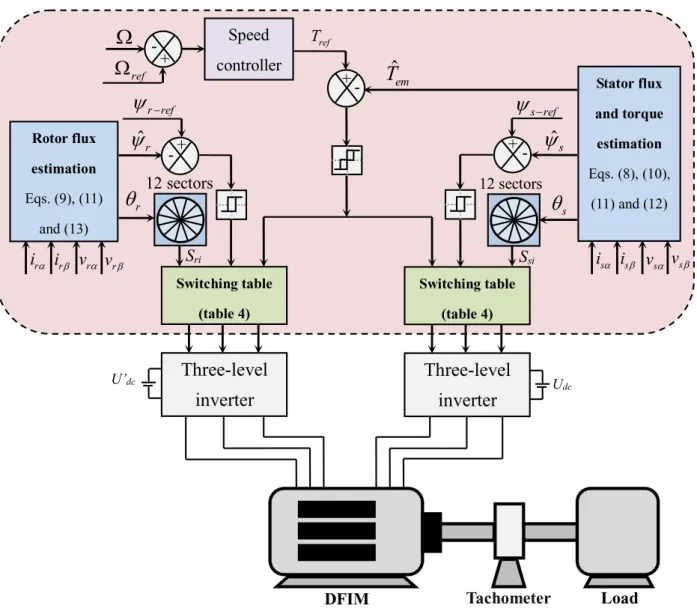
The power supply of the doubly fed induction motor is assured by two 3LVSIs [15]. Figure1illustrates the syn-optic schema of the studied system.
In the literature, for a better representation of the be-havior of DFIM, it is necessary to use a specific and sim-ple model. The two-phase model (α,β) given by the Concordia transformation is largely used for direct torque control [16].
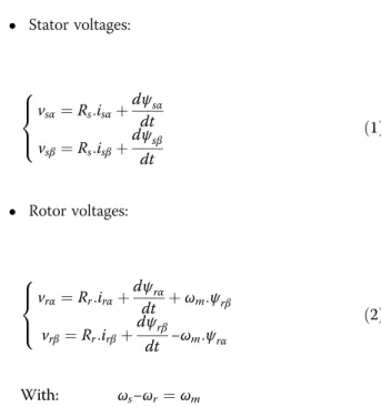
The electric equations of DFIM in the reference frame (α,β) are given by [17]:
Stator voltages:
vsα¼Rs:isαþ
dψsα dt
vsβ¼Rs:isβþ
dψsβ dt 8
> < >
: ð1Þ
Rotor voltages:
vrα¼Rr:irαþ
dψrα
dt þωm:ψrβ
vrβ¼Rr:irβþ
dψrβ
dt −ωm:ψrα 8
> < >
: ð2Þ
With: ωs−ωr¼ωm
The magnetic equations of DFIM in the reference frame (α,β) are expressed by:
Stator flux:
ψsα¼LsisαþLm:irα ψsβ¼LsisβþLm:irβ
ð3Þ
Rotor flux:
ψrα¼LrirαþLm:isα ψrβ¼LrirβþLm:isβ
ð4Þ
The electromagnetic torque expression of DFIM as a function of the stator flux and stator currents is written as follows [18,19]:
Tem¼p: ψsαisβ−ψsβisα
ð5Þ
The fundamental equation of dynamics is:
J:dΩ
dt þf:Ω¼Tem−Tr ð6Þ
3 Direct torque control strategy
3.1 DTC strategy for the DFIM connected to two 2LVSIs The principle of DTC is based on the direct regula-tion of the torque and flux of DFIM, by applying the different voltage vectors of inverters (tow-level) [5]. The choice of these vectors is made using two switching tables and the hysteresis regulators whose role is to control the electromagnetic torque and flux of the motor in a decoupled manner. The output of
these switching tables determines the optimal voltage vector of inverter to be applied at each switching instant.
The vector voltage expression of each two-level in-verter can be given in the form below [2]:
V¼pffiffiffiffiffiffiffiffiffiffiffiffiffið2=3Þ:Udc: SaþSbeðj2π=3ÞþSceðj4π=3Þ
ð7Þ
With:Sa, Sb, Scare switching logic states.
Figure 2 presents the set of voltage vectors delivered by each inverter.
In DTC, the accuracy of electromagnetic torque and flux estimation is very important to ensure satisfactory performance. The stator and rotor flux are estimated from the following eqs. [5]:
^
ψs¼
ffiffiffiffiffiffiffiffiffiffiffiffiffiffiffiffiffiffiffi ^
ψ2 sαþψ^
2 sβ
q
ð8Þ
^
ψr ¼
ffiffiffiffiffiffiffiffiffiffiffiffiffiffiffiffiffiffiffi ^
ψ2 rαþψ^
2 rβ
q
ð9Þ
The electromagnetic torque is estimated from the measured stator currents:
Tem¼p: ψrαirβ−ψrβirα
ð10Þ
With: Fig. 2Voltage vectors delivered by the two-level inverter
Table 1Switching states of the two-level inverter
Flux 0 1
Torque −1 0 1 −1 0 1
Sectors(Si) S1: [−30°, 30°] V5 V0 V3 V6 V7 V2
S2: [30°,90°] V6 V7 V4 V1 V0 V3
S3: [90°,150°] V1 V0 V5 V2 V7 V4
S4: [150°,210°] V2 V7 V6 V3 V0 V5
S5: [210°,270°] V3 V0 V1 V4 V7 V6
S6: [270°,330°] V4 V7 V2 V5 V0 V1
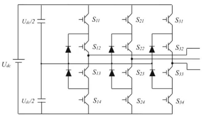
Fig. 3Schema of three-level inverter with NPC structure
Table 2Switching states of the three-level inverter
Switching states Sk1 Sk2 Sk3 Sk4 V
2 ON ON OF OF Udc/2
1 OF ON ON OF 0
^
ψsα¼
Zt
0
vsα−Rs:isα
ð Þ:dt
^
ψsβ ¼
Zt
0
vsβ−Rs:isβ
:dt 8 > > > > > > < > > > > > > : ^
ψrα¼
Zt
0
vrα−Rs:irα
ð Þ:dt
^
ψrβ¼
Zt
0
vrβ−Rs:irβ
:dt 8 > > > > > > < > > > > > > :
ð11Þ
The positions of stator and rotor flux are determined by:
θs¼arctg ψ^^sβ
ψsα
!
ð12Þ
θr¼arctg ψr^^β
ψrα
!
ð13Þ
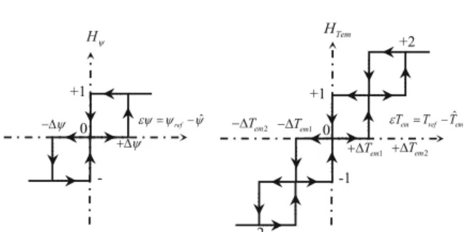
The estimated values of the electromagnetic torque and flux are compared respectively to their reference values; the comparison results form the inputs of hysteresis comparators [20]. The stator and rotor flux are controlled using the two-level hysteresis compara-tors, while the electromagnetic torque is controlled using a three-level hysteresis comparator. The flux space
is divided into six sectors of 60° each. The selection of the appropriate voltage vector is based on the control table shown in Table 1 [7]. The inputs of this table are the flux sector number and the outputs of hysteresis comparators.
3.2 DTC strategy for the DFIM connected to two 3LVSIs The development of speed control and DTC of doubly fed induction motors has favored the use of three-level inverters. The increase in levels number of the latter proves to be a better solution in high power drives. The inverter is made up of switching cells, generally with transistors or GTO thyristors for large powers [21]. In this section, we present the study DFIM associated with two 3LVSIs with neutral point camped structure con-trolled by the DTC algorithm. Figure 3 illustrates the general schema of 3LVSI with NPC structure; it is one of the structures of three-level inverter. It has a lot of advantages, such as the higher number of voltage vectors generated, less harmonic distortion and low switching frequency [22]. Each arm of the inverter consists of 4 switches:Sk1,Sk2,Sk3,Sk4. TheSk1and Sk2have comple-mentary operation.
On the control side, this converter topology offers the following advantages: high number of freedom degrees compared to the two-level inverter and reduced output current ripples.
The mathematical model of the 3LVSI is represented by the following matrix [23]:
Va Vb Vc 2 4 3 5¼1
3:Udc:
2 −1 −1
−1 2 −1
−1 −1 2
2 4
3
5: SS1121::SS22−12−SS1323::SS1424
S31:S32−S33:S34
2 4
3 5
ð14Þ
With:
Va, Vb, Vc: Phase voltages. Ski: Switching state. Udc: DC bus voltage.
Each arm of the three-level inverter has three switch-ing states shown in Table2.
Table 3Voltage vectors associated with switching states
Vector voltage Symbol
Zero vectors V0, V7and V14
Large vectors V15, V16, V17, V18, V19and V20
Medium vectors V21, V22, V23, V24, V24, V25and V26
Small vectors V1, V2, V3, V4, V5, V6, V8, V9, V10, V11, V12, V13
Fig. 4Voltage vectors of three-level NPC inverter
The set of voltage vectors delivered by a three-level in-verter are shown in Table 3, they are divided into 4 groups.
The 3LVSI produces 27 voltage vectors; some of them apply the same voltage vector. There are two possible configurations for each small vector and three for the zero vectors. Therefore, 19 different vectors are available in a three-level inverter [22]. The distribution of these voltage vectors in the reference frame (α, β) is shown in Fig.4.
The estimated values of the torque and flux are respect-ively compared to their reference values. The comparison results form the hysteresis regulators inputs. The stator and rotor flux are controlled using the three-level hyster-esis comparators, while the electromagnetic torque is con-trolled using a five-level hysteresis comparator (Fig. 5). The flux space is divided into 12 sectors of 30° each.
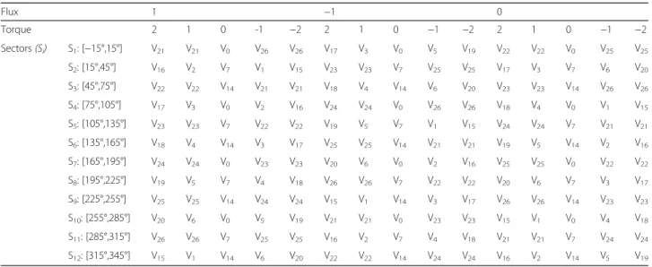
In order to realize the direct control of flux and torque of the DFIM connected to two three-level voltage in-verters with NPC structure, we need to develop the switching table that optimizes the inverter possibilities. The construction of this table (Table 4) depends on the choice of voltage vector applied to increase or decrease the flux modulus and electromagnetic torque value.
DTC scheme for the doubly fed induction motor con-nected to two 3LVSIs is illustrated in Fig.6.
4 Simulation results and discusions
The direct torque control strategy of doubly fed induc-tion motor was validated by numerical simulainduc-tion using MATLAB/SIMULINK environment. The DFIM parame-ters used in the simulation are given in the Appendix.
The main features of this simulation are summarized as follows:
The widths of the hysteresis bands:
ΔTem1= ±0.02 N.m, ΔTem2= ±0.04 N.m, Δψs= ±0.001
N.m andΔψr= ±0.001 N.m.
The sampling frequency: fs= 10 kHz.
The simulation results of the DTC strategy of DFIM powered by two 2LVSIs are shown in Fig.7.
Figure 7a shows the motor rotation speed. The speed reference changes from zero to 100 rad/s with specific acceleration rate (500 rad/s2), then it reduces to −100 rad/s at t = 1 s. It can be seen that the speed reference has been properly tracked without any overshoot.
The load torque, torque reference and motor torque are represented in Fig.7b. Here, the load torque is con-sidered as disturbance, and the control method must track the speed reference independent of the load torque. The load torque changes from 0 Nm to 10 Nm at t = 0.5 s, then it decreases to 5 Nm at t = 1.5 s. The electromagnetic torque tracks its reference. Moreover, this torque has more ripples of 2.632 Nm.
Figure 7c and d show that the stator and rotor flux modulus follows perfectly its reference (1 Wb for stator flux, 0.5 Wb for rotor flux), as well as the evolution of these flux in (α,β) plan illustrated in Fig.7e and f are perfectly circular.
Figure 7g represents the sectors repartition of stator and rotor flux in (α,β) plan, which shows that the DTC technique principle using 2LVSIs is ensured.
The stator and rotor currents of the DFIM are illus-trated in Fig.7h, the results show that the motor currents are sinusoidal. The harmonic spectra analysis of these cur-rents is shown in Fig.7i and j. Besides, the THD of stator Table 4Switching table
Flux 1 −1 0
Torque 2 1 0 -1 −2 2 1 0 −1 −2 2 1 0 −1 −2
Sectors(Si) S1: [−15°,15°] V21 V21 V0 V26 V26 V17 V3 V0 V5 V19 V22 V22 V0 V25 V25
S2: [15°,45°] V16 V2 V7 V1 V15 V23 V23 V7 V25 V25 V17 V3 V7 V6 V20
S3: [45°,75°] V22 V22 V14 V21 V21 V18 V4 V14 V6 V20 V23 V23 V14 V26 V26
S4: [75°,105°] V17 V3 V0 V2 V16 V24 V24 V0 V26 V26 V18 V4 V0 V1 V15
S5: [105°,135°] V23 V23 V7 V22 V22 V19 V5 V7 V1 V15 V24 V24 V7 V21 V21
S6: [135°,165°] V18 V4 V14 V3 V17 V25 V25 V14 V21 V21 V19 V5 V14 V2 V16
S7: [165°,195°] V24 V24 V0 V23 V23 V20 V6 V0 V2 V16 V25 V25 V0 V22 V22
S8: [195°,225°] V19 V5 V7 V4 V18 V26 V26 V7 V22 V22 V20 V6 V7 V3 V17
S9: [225°,255°] V25 V25 V14 V24 V24 V15 V1 V14 V3 V17 V26 V26 V14 V23 V23
S10: [255°,285°] V20 V6 V0 V5 V19 V21 V21 V0 V23 V23 V15 V1 V0 V4 V18
S11: [285°,315°] V26 V26 V7 V25 V25 V16 V2 V7 V4 V18 V21 V21 V7 V24 V24
current isais equal to 8.75% and THD of rotor current ira
is equal to 9.87%. The switching state of switch (Sa) of the
two-level inverter is given in Fig. 7k. The switching fre-quency is variable, its average value is equal to 4 kHz.
The simulation results of the DTC strategy of DFIM connected to two 3LVSIs are shown in Fig.8.
The results show the high performance of proposed method. From Fig. 8a, it can be seen that the rotation speed track its reference without overshoot, with a very low relative fall during the torque inversion, the release time is equal to 50 ms.
Figure8b clearly shows good torque dynamics which per-fectly follow its steady state reference with a fast response time. Moreover, the torque has small ripples of 0.972 Nm. From the analysis of Fig.8c and d it follows that the stator and rotor flux modulus follows perfectly its reference with less ripples, as well as the evolution of these flux in (α,β) plan shown in Fig.8e and f are perfectly circular.
Figure 8g represents the sectors repartition of the stator and rotor flux in (α,β) plan, there are 12 sectors which shows that the proposed method is ensured.
The components of the stator and rotor currents in reference frame (a,b,c) are shown in Fig. 8h, the motor currents are sinusoidal with a frequency proportional to the reference speed. These currents respond effectively to the variations imposed by load torque. Furthermore, Fig.8i and j present the harmonic spectra analysis of the stator and rotor currents absorbed by DFIM, the results indicate that the total harmonic distortions of these cur-rents are considerably reduced compared to the results obtained by DTC using 2LSVI (THD = 1.57% for stator current isa, THD = 1.52% for rotor current ira). The
switching state of three-level inverter is given in Fig.8k, the switching frequency is almost constant around 2.9 kHz, lower than that of DTC using 2LVSIs, which re-duces switching losses.
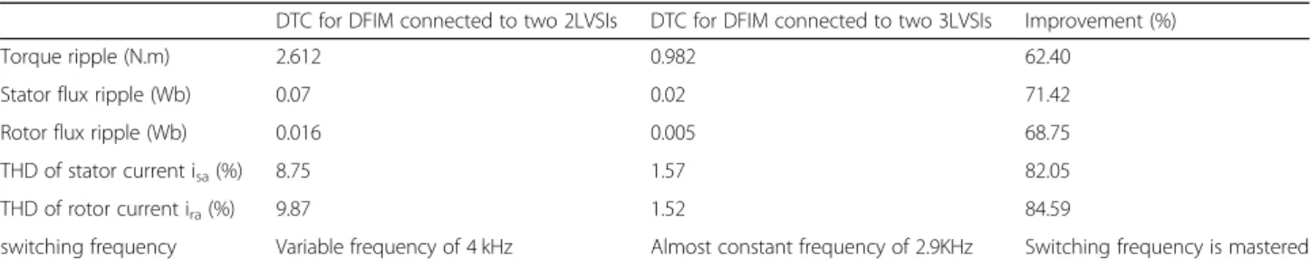
Table 5 summarizes the comparative study between the two methods. The results of comparison show re-markable improvements obtained by DTC using 3LVSIs. These improvements include an important reduction in flux and torque ripples, as well as a minimization in the harmonics of the stator and rotor currents. Therefore, the proposed method provides better performance com-pared to DTC using 2LVSIs.
5 Conclusion
In this paper, we have presented the direct torque control for a doubly fed induction motor connected to two three-level voltage source inverters with NPC structure. The objective is to improve the motor per-formance. The DFIM modeling and DTC technical using 3LVSIs is developed in detail. Simulation results
of the proposed method are comparatively analyzed against conventional DTC using 2LVSIs to confirm the effectiveness and superiority of the proposed con-trol. The results analysis shows that the DTC using 3LVSIs provides better performance in terms of
minimization of torque and flux ripples and
optimization of currents distortion. This provides an opportunity for motor operation under minimum switching loss and noise. The experimental validation of the proposed method on a dSPACE controller board is considered future work.
5.1 Methods/experimental
This study presents a method for improving the per-formance of the direct torque control. The doubly fed induction machine is used as a motor connected to two Fig. 7Simulation results of DTC using 2LVSIs: (a) Rotation
speed (b) Electromagnetic torque (c) Stator flux (d) Rotor flux (e) Stator flux trajectory (f) Rotor flux trajectory (g) stator and rotor flux sectors (h) Stator and rotor currents (i) FFT analysis of stator current isa(j) FFT analysis of rotor current ira (k) Switching state Sa
three-level voltage source inverters. The system model-ing and control are implemented in Matlab/Simulink en-vironment. Comparison analysis of the proposed method with conventional DTC illustrates the advantages of this method.
6 Nomenclature
vs(α,β),vr(α,β) Stator and rotor voltages in the reference frame (α,β).
is(α,β), ir(α,β) Stator and rotor currents in the reference frame (α,β).
ψs(α,β),ψr(α,β)Stator and rotor flux in the reference frame (α,β).
Rs, RrStator and rotor resistances. Ls, LrStator and rotor inductances. MMutual inductance.
PPole pair number.
ωs,ωrStator and rotor pulsations. ωMechanical pulsation.
TrLoad torque.
TemElectromagnetic torque. ΩRotation speed of the machine.
JMoment of inertia.
fCoefficient of viscous friction.
θs,θrPosition of the stator and rotor flux. UdcDC bus voltage.
Abbreviations
2LVSI:Two-Level Voltage Source Inverter; 3LVSI: Three-Level Voltage Source Inverter; DFIM: Doubly Fed Induction Motor; DTC: Direct Torque Control; FOC: Field Oriented Control; IM: Induction Motor; NPC: Neutral Point Clamped; PMSM: Permanent Magnet Synchronous Motor; SC: Scalar Control; THD: Total Harmonics Distortion
Acknowledgements
The authors would like to thank the anonymous reviewers for their helpful and constructive comments that greatly contributed to improving the final version of the paper. They would also like to thank the Editors for their generous comments and support during the review process.
Authors’contributions
NE, AD and AE performed the study of the direct torque control strategies, MT and YM corresponding, engaged in modifying the paper and submitted it to the PCMP. BB, KM and YM checked the grammar and writing of the paper. All authors read and approved the final manuscript.
Funding
The work is not supported by any funding agency. This is the authors own research work.
Availability of data and materials
Data sharing not applicable to this article as no datasets were generated or analyzed during the current study.
Competing interests
The authors declare that they have no competing interests.
Author details
1
Laboratory of Production Engineering, Energy and Sustainable Development, Higher School of Technology, Sidi Mohamed Ben Abdellah University, Fez, Morocco.2Laboratory of Systems Integration and Advanced Technologies, Faculty of Sciences Dhar El Mahraz, Sidi Mohamed Ben Abdellah University, Fez, Morocco.3Laboratory of Electrical Engineering and Maintenance, ESTO School of Technology, University Mohammed I, Oujda, Morocco.
Received: 27 November 2018 Accepted: 9 September 2019
References
1. Takahashi, I., & Noguchi, T. (1986). A new quick-response and high-efficiency control strategy of an induction motor. IEEE Transactions on Industry Applications, 5, 820–827.
2. El Ouanjli, N., Derouich, A., El Ghzizal, A., Chebabhi, A., & Taoussi, M. (2017). A comparative study between FOC and DTC controls of the doubly fed induction motor (DFIM). In International conference on electrical and information technologies: IEEE.
3. Reza, C. M. F. S., Islam, M. D., & Mekhilef, S. (2014). A review of reliable and energy efficient direct torque controlled induction motor drives.Renewable and Sustainable Energy Review, 37, 919–932.
4. Sutikno, T., Idris, N. R. N., & Jidin, A. (2014). A review of direct torque control of induction motors for sustainable reliability and energy efficient drives. Renewable and Sustainable Energy Review, 23, 548–558.
Table 5Comparison between our proposal and DTC using 2LVSIs
DTC for DFIM connected to two 2LVSIs DTC for DFIM connected to two 3LVSIs Improvement (%)
Torque ripple (N.m) 2.612 0.982 62.40
Stator flux ripple (Wb) 0.07 0.02 71.42
Rotor flux ripple (Wb) 0.016 0.005 68.75
THD of stator current isa(%) 8.75 1.57 82.05
THD of rotor current ira(%) 9.87 1.52 84.59
switching frequency Variable frequency of 4 kHz Almost constant frequency of 2.9KHz Switching frequency is mastered
1 Appendix
Table 6Parameters of the DFIM
Variable Symbol Value (unit)
Nominal power Pm 1.5 kW
Frequency f 50 Hz
Pair pole number P 2
Stator inductance Ls 0.295 H
Rotor inductance Lr 0.104 H
Mutual inductance M 0.165 H
Stator resistance Rs 1.75Ω
Rotor resistance Rr 1.68Ω
Total viscous frictions f 0.0027 Kg.m2/s
5. El Ouanjli, N., Derouich, A., El Ghzizal, A., El Mourabit, Y., Bossoufi, B., & Taoussi, M. (2017). Contribution to the performance improvement of doubly fed induction machine functioning in motor mode by the DTC control. International Journal of Power Electronics and Drive Systems, 8, 1117–1127. 6. Bonnet, F., Vidal, P. E., & Pietrzak-David, M. (2006). Direct torque control of
doubly fed induction machine.Bulletin of the Polish Academy of Sciences, 54, 307–314.
7. El Ouanjli, N., Motahhir, S., Derouich, A., El Ghzizal, A., Chebabhi, A., & Taoussi, M. (2019). Improved DTC strategy of doubly fed induction motor using fuzzy logic controller.Energy Reports, 5, 271–279.
8. Zemmit, A., Messalti, S., & Harrag, A. (2016). Innovative improved direct torque control of doubly fed induction machine (DFIM) using artificial neural network (ANN-DTC). International Journal of Applied Engineering Research, 11(16), 9099–9105.
9. El-Saadawi, M., & Hatata, A. (2017). A novel protection scheme for synchronous generator stator windings based on SVM. Protection and Control of Modern Power Systems, 2(1), 24.
10. El Ouanjli, N., Taoussi, M., Derouich, A., Chebabhi, A., El Ghzizal, A., & Bossoufi, B. (2018). High performance direct torque control of doubly fed induction motor using fuzzy logic.Gazi University Journal of Science, 31(2), 532–542.
11. Aissa, O., Moulahoum, S., Kabache, N., & Houassine, H. (2014). Improvement of DTC of induction motors by using a three-level inverter and fuzzy speed controller. In22 nd Mediterranean conference of control and automation(pp. 73–78).
12. Mohan, D., Zhang, X., & Foo, G. H. B. (2016). A simple duty cycle control strategy to reduce torque ripples and improve low-speed performance of a three-level inverter fed DTC IPMSM drive.IEEE Transactions on Industrial Electronics, 64(4), 2709–2721.
13. Kiran, T. V., & Amarnath, J. (2012). A sliding mode controller based DTC of 3 levels NPC inverter fed induction motor employing space vector modulation technique. In International conference on advances in engineering, Science and Management(pp. 372–377).
14. Guven, S., Usta, M. A., & Okumus, H. I. (2018). An improved sensorless DTC-SVM for three-level inverter-fed permanent magnet synchronous motor drive.Electrical Engineering, 100(4), 2553–2567.
15. El Ouanjli, N., Derouich, A., El Ghzizal, A., Chebabhi, A., Taoussi, M., & Bossoufi, B. (2018). Direct torque control strategy based on fuzzy logic controller for a doubly fed induction motor. In IOP conference series: Earth and environmental science (Vol. 161, No. 1, p. 012004). IOP Publishing. 16. Ammar, A., Bourek, A., & Benakcha, A. (2017). Nonlinear SVM-DTC for
induction motor drive using input-output feedback linearization and high order sliding mode control.ISA Transactions, 67, 428–442.
17. Boubzizi, S., Abid, H., & Chaabane, M. (2018). Comparative study of three types of controllers for DFIG in wind energy conversion system.Protection and Control of Modern Power Systems, 3(1), 1–21.
18. Mensou, S., Essadki, O., Nasser, T., & Idrissi, B. B. (2017). An efficient nonlinear Backstepping controller approach of a wind power generation system based on a DFIG.International Journal of Renewable Energy Research, 7(4), 1520–1528.
19. Taoussi, M., Karim, M., Hammoumi, D., El Bekkali, C., Bossoufi, B., & El Ouanjli, N. (2017). Comparative study between Backstepping adaptive and field-oriented control of the DFIG applied to wind turbines. In Advanced Technologies for Signal and Image Processing.
20. El Ouanjli, N., Derouich, A., El Ghzizal, A., Motahhir, S., Chebabhi, A., El Mourabit, Y., & Taoussi, M. (2019). Modern improvement techniques of direct torque control for induction motor drives - a review.Protection and Control of Modern Power Systems, 4, 1–12.
21. Naas, B., Nezli, L., Naas, B., Mahmoudi, M. O., & Elbar, M. (2012). Direct torque control based three level inverter-fed double star permanent magnet synchronous machine.Energy Procedia, 18, 521–530.
22. Ben youssef, E., Meroufel, A., & Barkat, S. (2015). Three-level DTC based on fuzzy logic and neural network of Sensorless DSSM using extended Kalman filter.Int J Power Electron Drive Syst, 5(4), 453–463.