Sharif University of Technology
Scientia IranicaTransactions A: Civil Engineering www.scientiairanica.com
Extent of riprap layer with dierent stone sizes around
rectangular bridge piers with or without an attached
collar
M. Karimaee Tabarestani, A.R. Zarrati
, M.B. Mashahir and E. Mokallaf
Department of Civil and Environmental Engineering, Amirkabir University of Technology, Tehran, Iran.Received 25 January 2014; received in revised form 25 June 2014; accepted 6 October 2014
KEYWORDS Local scour; Rectangular bridge pier;
Critical region; Riprap extent; Collar; Riprap sizing.
Abstract. In the present study, the extent of riprap layer with dierent sizes around bridge piers is investigated. Rectangular pier with or without an attached protective collar aligned with the ow and skewed at dierent angles are tested. The optimal congurations of riprap extent for each pier condition with dierent sizes are determined. Experiments showed that in case of aligned rectangular pier without a collar only 8% of the area around the pier is critical and the remaining 92% area can be protected with about 60% smaller riprap stones. As the skew angle of the pier increases up to 20, the critical area increases
up to 23% of the riprap extent. In case of protected pier with collar, the collar prevents the critical region around the pier in aligned and 5 skewed pier. However, by increasing
the ow attack angle up to 20, only a small area up to 30% in the riprap extent around
the collar is critical and the remaining area can be placed with 40% smaller riprap size. Finally, the design algorithm for riprap extent with dierent sizes is presented.
c
2015 Sharif University of Technology. All rights reserved.
1. Introduction
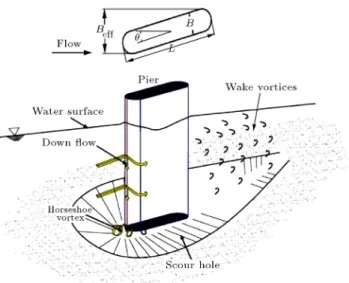
Local scouring around bridge piers occurs due to a complex ow eld with large-scale turbulence struc-tures generated by ow around the pier. As shown in Figure 1, notable structures are the horseshoe vortex, surface roller and wake vortices [1-3]. Experimental results show that dierent regions around a pier are exposed to dierent ow forces due to the action of horseshoe and wake vortices [4,5]. These forces include high shear stresses around the upstream face and sides of the pier which are under the action of down ow and horse shoe vortex and uplift forces in the wake of the pier under the action of wake vortices [6]. Obviously, strength of these forces reduces at further distances from the periphery of the pier.
*. Corresponding author. Tel.:+98 21 64543002; Fax: +98 21 66414213
E-mail address: [email protected] (A.R. Zarrati)
Due to the danger of bridge failure when piers are undermined, many methods have been presented in the last two decades for preventing scouring. These methods include devices which change the ow pattern to reduce the ow force such as collars [7-11], sacricial piles placed upstream of the pier [12], slots [8,13,14] and Iowa vanes [15], and methods with increasing the streambed resistance with using some materials such as riprap stones, cable-tied blocks, tetrapods, dolos, etc. [5,16-21]. Among devices used to change the ow pattern around piers, collars attached to the pier were investigated by more researchers. Collars prevent the direct impact of down ow and reduce the local scour depth due to decreasing the down ow strength and, therefore, the horseshoe vortex below the collar (Figure 2). The eciency of a collar depends on its size and location on the pier with respect to the bed [4,5]. Though a collar prevents the action of horse shoe vortex, it cannot prevent scouring due to the action of wake vortices. Among dierent suggested
Figure 1. Schematic vortex structures around circular pier.
Figure 2. Scouring and ow pattern around a rectangular pier protected by a collar.
armoring methods, application of riprap layer around a pier is very common. Design of riprap layer involves nding stable size, optimum extent and thickness of riprap stones [16,22-24]. Numerous studies have been conducted to determine stable riprap size and extent around circular piers. Comparing with circular piers, design of riprap layer around rectangular piers involves two additional parameters, which are the pier aspect ratio and skew angle.
Most of the previous equations presented for riprap design around bridge pier can be rewritten in term of riprap stability number [5,15,17,25,26]. This parameter indicates the relationship between the ow condition and riprap stone characteristics and can be written as:
Nc= :U 2
g:(s ):d50; (1)
where Nc is riprap stability number; U is the
undis-turbed upstream depth-averaged ow velocity; d50
is the median size of stable riprap stones; g is the gravitational acceleration; is the uid density; and s is the riprap stone density. In addition, square
root of Nc is called the Densimetric Particle Froude
Number, which was also used by some researchers as an essential parameter aecting scour depth around hydraulic structures [27,28]. A list of dierent riprap design equations based on riprap stability number is presented in [5].
Mashahir et al. [19] studied the extent of riprap layer around rectangular piers unprotected and pro-tected with a collar. Piers with dierent aspect ratios and skew angles were considered in this work. They found that application of a collar at the stream bed reduces the riprap extent by about 35 percent in piers aligned with the ow at all aspect ratios. However, with increasing the ow attack angle, the eect of collar on the area of stable riprap layer is reduced.
All previous studies considered a single riprap size in the stable riprap layer, whereas dierent regions of streambed around a pier are exposed to dierent ow forces. Therefore, smaller riprap sizes could be used in regions with lower ow forces to reduce the costs. This is especially important for rectangular piers where the extent of riprap layer around them is very large particularly at higher aspect ratios and skew angles. The present study is focused on designing the extent of riprap layer with dierent riprap sizes around rectangular pier with and without an attached collar and in dierent skew angles. For this purpose, a series of experiments were carried out which are explained in the following sections.
2. Experimental setup
Experiments were performed in a 10 m long, 0.74 m wide, and 0.6 m deep laboratory horizontal ume. The ume had a working section in the form of a recess below its bed, which was lled with sediment and was located 6 m downstream of the ume entrance. Median size of the sediment, d50, was 0.95 mm with geometric
standard deviation of sediment grading, g, as dened
below, less than 1.3. g=
d84
d16
0:5
; (2)
where da is the size of sediment for which a percent of
material by weight is ner.
A rectangular pier model, with a circular nose and tail made from Perspex was used in these tests. Width (B) and length (L) of this pier were 50 mm, and 250 mm, respectively (Figure 2). Therefore, the aspect ratio (L=B) of this pier was 5. Flow depth was measured with a point gauge with 0.1 mm accuracy. Discharge was measured with a calibrated sharp crested weir installed at the downstream end of the ume.
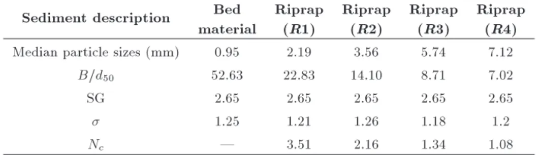
Table 1. Properties of bed material and riprap stones. Sediment description Bed
material
Riprap (R1)
Riprap (R2)
Riprap (R3)
Riprap (R4) Median particle sizes (mm) 0.95 2.19 3.56 5.74 7.12
B=d50 52.63 22.83 14.10 8.71 7.02
SG 2.65 2.65 2.65 2.65 2.65
1.25 1.21 1.26 1.18 1.2
Nc | 3.51 2.16 1.34 1.08
Note: SG is relative riprap stone density.
All tests were conducted at the threshold of bed material motion. The threshold of bed material motion was found by experiment when the pier was not installed. These tests showed that with 0.13 m ow depth and discharge of 0.034 m3/s, bed material
would be at incipient motion. In these experiments, the ratio of shear velocity calculated from ow depth and energy slope at the working section (u) to the critical shear velocity calculated from Shields diagram (uc) was about u =uc = 0:92.
Riprap materials with four dierent sizes (R1 to R4) were used in this study. The median particle sizes for these riprap materials, together with bed sediment, are given in Table 1. In addition to riprap characteristics, the riprap stability parameter (Nc) for
each riprap size was also calculated based on the ow condition and is given in Table 1.
The extent of riprap layer around the pier in each experiment was considered based on what suggested by Mashahir et al. [20] and was found to be stable. However, the nal conguration of riprap extent in cases of aligned unprotected and protected pier with collar was simplied by removing the downstream curve parts and substituting them with straight lines.
The top surface of the riprap layer was always leveled with the bed elevation. To prevent winnowing failure, the thickness of riprap layer in all tests was 2:5d50 where d50is median size of riprap stones [17].
To ensure stability of riprap layer in the present work, experiments were conducted for 10 hours. After 10 hours if no riprap stone was removed and the scour hole around the riprap layer was less than one riprap size, that layer was considered as stable with no shear or edge failure.
In the present work, the rst series of experiments were carried out with pier aligned or skewed with 5,
10and 20angles corresponding to the ow direction.
The necessary extent of riprap layer was then found by experiment. In addition, zones of lower ow forces which can be covered with ner sediment size were recognized.
In the next stage, a collar was attached to the pier, and the rst series of tests were repeated to study the eect of collar on stable riprap size and extent.
Due to its eciency and acceptable size, a collar with W=B = 3 at the streambed level was used in all experiments where `W ' is the collar eective width (Figure 2) and `B' is the pier width [8,9]. For both series of experiments, the critical region with highest ow forces was called Zone 1. Zones with lower ow forces which were stable with ner sediment size were, respectively, called Zone 2 and Zone 3.
3. Riprap design equation
Based on large amount of experimental data, Karimaee and Zarrati [5] presented the following equation for design of stable riprap around aligned and skewed round nose rectangular as well as circular piers:
Nc= 2:85 K1 K2 K3: (3)
In the above equation, K1 = pd50=B is riprap
size adjustment factor where B is the round nose rectangular pier width or circular pier diameter, and, K2 = (y=d50)0:25 is the ow depth adjustment factor
K3= (B=Be)1:5is the eective pier width adjustment
factor where Be is equal to circular pier diameter or
projected length of the rectangular pier perpendicular to the ow direction which is dened as Be = L
Sin + B (1 Sin) where L is the rectangular pier length and is the pier skew angle. For circular as well as aligned rectangular pier, Be is equal to B.
Since a collar protects the regions close to a pier, which are exposed to higher stresses, lower riprap size is necessary to protect the area around the collar. Mashahir et al. [20] and Karimaee and Zarrati [5] showed that for skewed piers the regions at downstream and leeward side of the pier are also exposed to high ow forces. In the present work, it was decided to develop Eq. (3) for design of stable riprap around protected pier with a collar. Eq. (3) can therefore be written as:
Nc= 2:85 K1 K2 K3 K4; (4)
where K4is collar adjustment factor which adjusts the
calculated Ncin case the pier is protected with a collar.
Table 2. Percentage of riprap area at dierent zones around the pier. Pier skewed Percentage of riprap area Ratio of riprap extent
angle Zone 1
(critical zone) Zone 2 Zone 3
area to pier section area
Aligned pier 8 92 - 9.7
5 9 91 - 12.4
10 22 78 - 15.9
20 23 12 65 17.5
al. [20] for a collar with W=B = 3 at the streambed level (see Figure 2) and in dierent pier aspect ratios, the following relationship was derived for K4:
K4=
8 < :
1:6 for Be=B < 1:7
1:0 for Be=B 1:7
(5) based on Eq. (4), for Beff=B < 1:7 (low rectangular
pier aspect ratio or skew angle or for circular pier) the parameter Nc increases by 60%. This is equivalent
to decreasing stable riprap size d50 by about 30%.
For Beff=B 1:7 collar has negligible eect on
stable riprap size. Extent of riprap layer for piers with dierent aspect ratios with and without collar protection is also given in Mashahir et al. (2010). 4. Experimental results
4.1. Riprap extent with dierent stone sizes around a pier without a collar
Aligned rectangular pier. In the rst stage of experiments, dierent riprap sizes were placed around the rectangular pier to check their stability. Exper-iments showed that riprap size with B=d50 = 14:1
(riprap R2 in Table 1) was stable all around the pier model. This riprap size conrms well with the predicted riprap size from Eq. (4). However, previous studies showed that, for aligned rectangular pier, the critical region with high ow forces is around the upstream nose of the pier under the action of down ow and concentration of shear stresses [5]. Therefore, new experiments were carried out to optimize the riprap extent conguration with ner stones in regions rather than the critical zone. Figure 3 shows the nal extent of two size riprap layer around the aligned pier.
Figure 3. Extent of riprap layer and zones with dierent riprap sizes around aligned unprotected rectangular pier.
Table 2 shows the percentage of area with dier-ent riprap sizes around the pier. It can be seen that from the whole riprap extent which is about 10 times the pier area, only 8% is critical (Zone 1) and should be covered with the riprap size calculated from Eq. (4) and the remaining area (Zone 2) can be covered with about 38% ner material (B=d50= 22:83).
Skewed rectangular pier. When pier was skewed corresponding to the ow direction, stronger action of the wake vortices with stronger suction eect was present downstream of the pier. Based on experimental observations it can be concluded that the combination of shear stresses and wake vortices at the separation zone are the main factor in moving the riprap stones in this region. This eect increases as the parameter Be=B increases (larger pier aspect ratio and pier skew
angle).
In 5 skewed pier, the critical region is at the
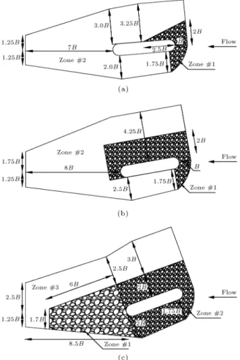
separation area downstream of the pier nose. Similar approaches to aligned pier were carried out to divide the riprap extent into two zones with dierent riprap size. Figure 4(a) shows the optimized layout. As shown in this gure, similar to the aligned pier, riprap R2 with B=d50 = 14:1 was stable in the critical
region at the upstream periphery of the pier, and riprap R1 with B=d50 = 22:83 could be used in the
remaining area. The critical region with designed riprap was only about 10% of riprap extent area and the remaining 90% could be covered with a ner riprap (Table 2).
For 10 skewed pier, the critical region was near
the leeward side of the pier in the separation area [5]. In this case, based on experimental observations, riprap R3 in Table 1 with d50= 5:74 mm or B=d50= 8:71 was
stable. This size also conforms to what was calculated from Eq. (4). Figure 4(b) shows the optimal riprap extent with two dierent sizes for 10 skewed pier. As
can be seen in this gure and Table 2, about 22% of the riprap layer which is about 16 times the pier diameter area is critical and the remaining area can be protected with smaller riprap size R1 which is about 62% smaller than riprap R3.
Finally, for 20 skewed pier, all downstream of
Figure 4. Extent of riprap layer with dierent sizes around skewed rectangular pier: a) 5skewed pier; b) 10
skewed pier; and c) 20skewed pier.
the separation area. In this case, experiments showed that riprap R4 in Table 1 with d50 = 7:10 mm or
B=d50= 7:02 was stable which conrms well to Eq. (4).
Many tests were carried out to determine the optimal conguration of the riprap layer extent with dierent sizes. Figure 4(c) and Table 2 show the nal results. About 23% of the riprap layer in the downstream of the pier was critical covered with R4 (Zone 1). The remaining area was divided into two dierent zones; Zone 2 with 12% and Zone 3 with 65% of the riprap extent area. Riprap R3 was stable in Zone 2 which is about 20% smaller than riprap R4; in Zone 3, riprap R2 which is about 50% smaller than riprap R4 could be used.
4.2. Riprap extent around the pier protected with a collar
In the second series of experiments, a collar with W=B = 3 was installed around the piers at the streambed level (Figure 2). Riprap with dierent sizes was then placed around the collar to determine the sucient extent of riprap layer. Aligned pier as well as skewed at 5, 10 and 20 were tested.
Figure 5. Extent of riprap layer around the protected aligned rectangular pier.
Figure 6. Extent of riprap layer with dierent sizes around the protected skewed rectangular pier: a) 5
skewed pier; b) 10skewed pier; and c) 20skewed pier.
Aligned rectangular pier. For aligned pier, due to existence of the collar, critical region close to the pier was well protected and therefore, only the areas around the collar were necessary to be covered by the ner riprap R1 which conforms well to what calculated from Eq. (4). Figure 5 illustrates the stable extent of riprap layer around the pier.
Skewed rectangular pier. For 5 skewed pier,
similar to the aligned pier, the critical region is near the upstream periphery of the pier, which is protected by the collar. Based on Eq. (4) and observation, riprap R1 was stable all around the collar in the riprap extent (Figure 6(a)).
Table 3. Percentage of riprap area at dierent zones around the protected pier with a collar. Pier skewed Percentage of riprap area Ratio of total riprap
angle Zone 1 Zone 2 extent area to the
pier section
Aliened pier 1 | 7.2
5 1 | 10.2
10 12.3 87.7 13.7
20 30 70 15.3
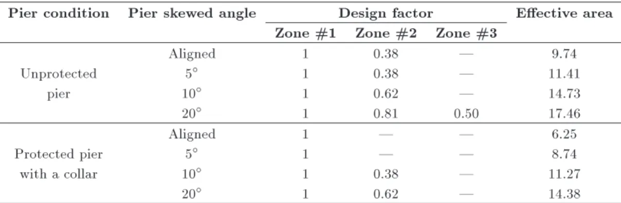
Table 4. Design factor for riprap stones at dierent zones.
Pier condition Pier skewed angle Design factor Eective area Zone #1 Zone #2 Zone #3
Unprotected pier
Aligned 1 0.38 | 9.74
5 1 0.38 | 11.41
10 1 0.62 | 14.73
20 1 0.81 0.50 17.46
Protected pier with a collar
Aligned 1 | | 6.25
5 1 | | 8.74
10 1 0.38 | 11.27
20 1 0.62 | 14.38
dierent riprap sizes for 10 skewed pier. In addition,
Table 3 shows the percentage of riprap extent at dierent zones around the protected pier. About 12% of the riprap extent is critical and the remaining area could be covered by 38% smaller riprap. Finally, for 20 protected skewed pier, it was concluded that the
critical region is mainly at the downstream tail of the pier. Figure 6(c) shows the nal conguration of riprap layer with two dierent sizes (two dierent zones). The critical zone which was about 30% of the riprap layer extent (Zone 1) was stable with riprap R3 which agrees with the size calculated from Eq. (4), and the remaining area could be covered with smaller stones (Table 3). 5. Design method for riprap extent with
dierent sizes
Eq. (4) predicts riprap stones to resist the maximum ow forces in the critical region around the pier. In order to calculate the riprap size in other regions, reduction factors for decreasing the designed riprap size are introduced in Table 4. The reduction factor for each zone was determined by dividing the stable riprap size in each zone to that in Zone 1 based on the present experimental results. The conguration of the riprap extent with dierent sizes are given in Figures 3 and 4 for unprotected and in Figures 5 and 6 for the protected pier with a collar. Further study is required to accurately determine the riprap zones boundary in dierent pier aspect ratios. However, since the necessary outer extent of riprap layer for dierent pier aspect ratios is given by Mashahir et al. (2010),
the present work can be used as a guide to estimate the critical zone area in dierent pier aspect ratios too. 6. Conclusion
In the present study, extent of riprap layer with dierent sizes around rectangular bridge piers was investigated experimentally. Rectangular pier with or without an attached collar aligned with the ow and skewed at dierent angles were tested.
At the rst stage of the studies, by analyzing the experimental data of Mashahir et al. [20], the riprap design equation presented by Karimaee and Zarrati [5] was developed for bridge piers protected by a collar. The analysis showed that in aligned piers the stable riprap size decreases about 30% in comparison to an unprotected pier.
As the strength of ow forces around a pier is dierent, smaller riprap sizes can be used in the areas with lower ow forces. Therefore, experiments were carried out to determine riprap extent with dierent sizes around an unprotected pier. These experiments showed that the riprap stones calculated by the riprap design equation are only needed in a small part of riprap extent (the critical zone), and smaller riprap sizes can be placed used in other parts. For example in case of aligned rectangular pier without collar only 8% of the riprap extent area was critical and the remaining 92% region could be covered with 60% smaller riprap size. As the pier skew angle increased, the critical region increased due to larger area of high ow forces in periphery and downstream of the bridge pier in wake
zone. For example, in case of 20 skewed pier, the
critical area increases to 23% of the riprap extent. In the next stage of the studies, similar approach was carried out to determine riprap extent with dif-ferent sizes for protected pier with a collar. For aligned and 5 skewed rectangular pier, experiments
showed that the critical region around the pier was well protected with collar. However, by increasing the ow attack angle up to 20, only a small area up to 30%
in the riprap extent around the collar is critical and the remaining area can be placed with 40% smaller riprap size. Finally, based on the present investigation, the design step method for riprap extent with dierent sizes was presented.
Nomenclature
y Undisturbed upstream ow depth U Undisturbed upstream depth-averaged
ow velocity
d50 Median size of stable riprap stones
g Geometric standard deviation of
sediment grading
da Size of sediment for which a percent of
material by weight are ner u Bed shear velocity
uc Critical shear velocity for the bed
material
SG Relative riprap stone density Fluid density
s Sediment density
Nc Riprap stability number
g Gravitational acceleration W Collar eective width B Pier width
Be Eective pier width
L Pier length Flow attack angle
K1 Riprap size adjustment factor
K2 Flow depth adjustment factor
K3 Eective pier width adjustment factor
K4 Collar adjustment factor
References
1. Melville, B.W. and Raudkivi, A.J. \Flow characteris-tics in local scour at bridge piers", J. Hydraul. Res., 15(4), pp. 373-380 (1977).
2. Ettema, R. \Scour at bridge piers", Rep. No. 216, School of Engineering, Univ. of Auckland, Auckland, New Zealand (1980).
3. Dargahi, B. \Controlling mechanism of local scouring", J. Hydraul. Eng., 116(10), pp. 1197-1214 (1990).
4. Zarrati, A.R., Gholami, H. and Mashahir, M.B. \Ap-plication of collar to control scouring around rectangu-lar bridge piers", J. Hydraul. Res., 42(1), pp. 97-103 (2004).
5. Karimaee, T.M. and Zarrati, A.R. \Design of stable stone size to prevent scouring around rectangular bridge piers", J. Hydraul. Eng., 139(8), pp. 911-916 (2013).
6. Raudkivi, A.J. Loose Boundary Hydraulics, Balkema, Rotterdam, The Netherlands (1998).
7. Tanaka, S. and Yano, M. \Local scour around a circular cylinder", Proc., 12th Congress of IAHR, Fort Collins, Colo., 3, pp. 193-200 (1967).
8. Kumar, V., Ranga Raju, K.G. and Vittal, N. \Re-duction of local scour around bridge piers using slot and collar", J. Hydraul. Eng., 125(12), pp. 1302-1305 (1999).
9. Zarrati, A.R., Nazariha, M. and Mashahir, M.B. \Reduction of local scour in the vicinity of bridge pier groups using collars and riprap", J. Hydraul. Eng., 132(2), pp. 154-162 (2006).
10. Karimaee, M. and Zarrati, A.R. \Eect of collar on time development and extent of scour hole around cylindrical bridge piers", Int. J. Eng., Transactions C, 25(1), pp. 11-16 (2011).
11. Tafarojnoruz, A., Gaudio, R. and Calomino, F. \Bridge pier scour mitigation under steady and un-steady ow conditions", Acta Geophysica, 60(4), pp. 1076-1097 (2012).
12. Melville, B.W. and Hadeld, A.C. \Use of sacricial piles as pier scour countermeasures", J. Hydraul. Eng., 125(11), pp. 1221-1224 (1999).
13. Grimaldi, C., Gaudio, R., Calomino, F. and Car-doso, A.H. \Countermeasures against local scouring at bridge piers: Slot and combined system of slot and bed sill", J. Hydraul. Eng., 135(5), pp. 425-431 (2009).
14. Chiew, Y.M. \Scour protection at bridge piers", J. Hydraul. Eng., 118(9), pp. 1260-1269 (1992).
15. Odgaard, A.J. and Wang, Y. \Scour prevention at bridge piers", Proc., Nat. Conf. Hydraul. Eng., ASCE, Williamsburg, Va., pp. 5253-5257 (1987).
16. Parola, A.C. \Stability of riprap at bridge piers", J. Hydraul. Eng., 119(10), pp. 1080-1093 (1993).
17. Chiew, Y.M. \Mechanics of riprap failure at bridge pier", J. Hydraul. Eng., 121(9), pp. 635-643 (1995).
18. Richardson, E.V. and Davis, S.R. \Evaluating scour at bridges", Hydraul. Eng. Circular, No. 18 (HEC-18 Fourth Edition), FHWA NHI 01-001, Federal Highway Administration, Washington D.C. (2001).
19. Lagasse, P.F., Clopper, P.E., Zevenbergen, L.W. and Girard, L.G. \Countermeasures to protect bridge piers
from scour", NCHRP Report 593, TRB, NAS, Wash-ington D.C., p. 272 (2007).
20. Mashahir, M.B., Zarrati, A.R. and Mokallaf, E. \Ap-plication of riprap and collar to prevent scouring around piers rectangular bridge", J. Hydraul. Eng., 136(3), pp. 183-187 (2009).
21. Froehlich, D.C. \Protecting bridge piers with loose rock riprap", J. Applied Water Eng. and Res., 1(1), pp. 39-57 (2013).
22. Chiew, Y.M. and Lim, F.H. \Failure behavior of riprap layer at bridge piers under live-bed condition", J. Hydraul. Eng., 126(1), pp. 43-55 (2000).
23. Lauchlan, C.S. and Melville, B.W. \Riprap protection at bridge piers", J. Hydraul. Eng., 127(5), pp. 412-418 (2001).
24. Zarrati, A.R., Chamani, M.R., Shafaei, A. and Lati, M. \Scour countermeasures for cylindrical bridge piers using riprap and combination of collar and riprap", I. J. Sed. Res., 25(3), pp. 313-321 (2010).
25. Quazi, M.E. and Peterson, A.W. \A method for bridge pier riprap design", Proc., 1st Can. Hydraul. Conf., pp. 96-106 (1974).
26. Croad, R.N. \Protection from scour of bridge piers using riprap", Transit New Zealand Res. Rep. No. PR3-0071, Works Consultancy Services Ltd., Central Laboratories, Lower Hutt, New Zealand (1997).
27. Rajaratnam, N. and Nwachukwu, B.A. \Erosion near groynelike structures", J. Hydraul. Res., 21(4), pp. 277-287 (1983).
28. Oliveto, G. and Hager, W.H. \Temporal evolution of clear-water pier and abutment scour", J. Hydraul. Eng., 128(9), pp. 811-820 (2002).
Biographies
Mojtaba Karimaee Tabarestani is a graduated PhD student in Hydraulic Engineering from Amirkabir University of Technology. He received his BSc in
Civil Engineering from Engineering Department of Mazandaran University, in Babol (Noshirvani Insti-tute of Technology), and his MSc in Hydraulic En-gineering from Amirkabir University of Technology. He is interested in mechanics of sediment transport and scouring phenomenon and its protection in river training structures and bridges. He is also a member of Iranian Hydraulic Association (IHA). Dr Karimaee is now an Assistant Professor in Water and Hydraulic Structure Engineering at the Department of Civil and Architectural Engineering, Shahab Danesh Institute of Higher Education, Qom, Iran.
Amir Reza Zarrati is a professor of Hydraulic En-gineering at the Department of Civil and Environmen-tal Engineering, Amirkabir University of Technology Tehran, Iran. He has more than 20 years of teaching and research experience. His main area of research is numerical and physical modeling of ow behavior, such as in hydraulic structures and rivers. He is also interested in scouring phenomenon and methods of its control. Dr. Zarrati has also a long collaboration with industry and has been senior consultant in a number of large dams in the country. He is a member of Iranian Hydraulic Association (IHA) and International Association of Hydraulic Research (IAHR).
Mohammad Badali Mashahir is a Graduate stu-dent of Amirkabir University of Technology. He received his BSc in water engineering from Tabriz University and his MSc in Hydraulic Engineering from Amirkabir University of Technology and is working in consulting engineering companies since graduation. Ebrahim Mokallaf is a PhD candidate of Hydraulic Engineering, Shahid Behshti University. He received his BSc in water engineering from Tabriz University and his MSc in Hydraulic Engineering from Amirkabir University of Technology.