Template-Based Optimal Robot Design with Application to
Passive-Dynamic Underactuated Flapping
Avik De and Robert J. Wood
Abstract— We present a novel paradigm and algorithm for optimal design of underactuated robot platforms in highly-constrained nonconvex parameter spaces. We apply this al-gorithm to two variants of the mature RoboBee platform, numerically demonstrating predicted performance improve-ments of over 10% in some cases by algorithmically reasoning about variable effective-mechanical-advantage (EMA) trans-missions, higher aspect ratio (AR) wing designs, and force-power tradeoffs. The algorithm can currently be applied to any underactuated mechanical system with one actuated degree of freedom (DOF), and can be easily extended to arbitrary configuration spaces and dynamics.
I. INTRODUCTION
Presented with a task requirement, the conventional paradigm in robotics is to map the task onto a fixed robot design (i.e., the control synthesis problem), but robot perfor-mance can often be drastically improved by considering the task at design-time [1], [2], [3]. In the holistic “co-design” approach, a parameterized vehicle design and the control inputs are simultaneously optimized [4], however, the co-design problem is quite challenging to pose and solve due to problems such as the inherent bilinearity of the inertial parameters and states1, and redundancy in the solution space. The authors of [4] use an approach that only performs local descent in the design variables, necessitating a good initial solution. For new vehicle designs or to more thoroughly explore the design space, a different approach is required.
In this paper, we propose a new paradigm for design based on task-specification using “templates” [5]: simplified models that exhibit the target behavior. In our usage, we specifically imply that the template model contains the least possible number of vehicle design parameters (in this paper: nondimensional) and no actuator constraints, while providing a behavioral “target” around which to optimize the physical vehicle design. To represent this behavioral target, in this paper we use an execution of the template dynamics without any anchoring design, resulting in a trajectory of (template) states and interaction forces. While in simple cases, this trajectory can be obtained via past experience or open-loop simulation, in more complex settings it may be appropriate to use optimal control on the reduced template dynamics—still a far simpler task than dealing with the full complexity of the anchoring design. The next step, optimizing the vehicle design against this target, is the topic of this paper.
This work was supported by JSMF grant #220020559, a fellowship held by the first author.
School of Engineering and Applied Sciences, Harvard University, Cam-bridge, MA, USA.(avikde,rjwood)@seas.harvard.edu
1as apparent from the product in the first summand of (2)
ψ φ Actuator Wing Transmission kφ τ1, τ2 Lw Aw wψ x z qact A B 5mm C D E
Regular wing Higher aspect ratio wing
Previous design Modified design
Fig. 1. The sources of experimental data in this paper are two variants of the RoboBee: BigBee [6]A, and the latest iteration of the split dual-actuator bee (SDAB) [7]B.Cdepicts our flapping wing model showing the two output DOFsφ, ψ, actuator displacementqact(blue), six out of seven
design parameters (red), and the wing frame (purple).D–E demonstrate SDAB performance improvements attained via the results in this paper via snapshots of the stroke kinematics at identical actuator inputs with two different wing types.
Our application area, autonomous insect-scale flapping-wing micro aerial vehicles (FWMAV), is an active area of research [7] [8] [9] [10] due to significant technological con-straints and conceptual challenges. These vehicles experience complex nonlinear fluid interactions, and are operated in regimes dominated by passive dynamics (resonance) which are sensitive to design parameters in a large parameter space conventionally navigated by fixing many axes and vary-ing others (componentwise optimization). Componentwise scaling predictions have had recent breakthrough success in enabling power-autonomy [8], but their predictions are correspondingly hostage to a number of simplifying as-sumptions such as (a) ideal at-resonance single operating points, precluding considerations of transient behaviors such as maneuvering, (b) ideal force-transmission characteristics, excluding variable-EMA designs, or (c) added model com-plexity from factors such as external wind, for high-speed flight. Additionally, the design space is highly non-convex, i.e., generally, componentwise descent in the design space is not guaranteed to converge. While we do not address all of these avenues of improvement in this paper, we shine a spotlight on variable-EMA designs while employing a holistic approach to vehicle design. In terms of task-specification, we leverage prior empirical research to extract favorable target template kinematics [9].
In this paper, we (a) present a novel scalable algorithm for design optimization of underactuated, passive-mechanics-2020 IEEE/RSJ International Conference on Intelligent Robots and Systems (IROS)
dominated robotic systems with constrained non-convex de-sign spaces (Sec. II), (b) propose a new model for passive-rotation wing flapping that has significantly fewer parameters than the state-of-the-art [7] while capturing the influence of the vehicle design to its performance (Sec.III), (c) demon-strate numerically predicted performance improvements of over 10% from current state-of-the-art vehicle components by algorithmic reasoning about variable-EMA transmissions and higher AR wing designs they can support (Sec. IV-B), and (d) demonstrate the wide applicability of the algorithm to designs at various scales while trading off force-power requirements in the objective function (Sec. IV-C).
II. DESIGNOPTIMIZATIONALGORITHM
In this section we present a novel algorithm for design optimization. We present the general form of our assumed dynamics model inII-Asubject to the following assumption:
Assumption 1. There is a singleactuatedDOF.2
We reformulate the dynamics in a special lumped-parameter-affine form that dramatically simplifies the opti-mization inII-B, and present the algorithm inII-C.
A. Lagrangian Dynamics With Intermediate Transmission 1) Dynamics in output coordinates: We assume a model of the form of a rigid-body chain subject to external forces with output (distal of transmission) configuration
q = (qa, qu) ∈ Q. With the Lagrangian L(q,q˙) := 1/2 ˙qTM(q) ˙q−γ(q), andEL the Euler-Lagrange operator, we define the dynamics terms3
h1(q,q˙) :=EL(1/2 ˙qTMq˙)−Mq¨
h2(q) :=EL(−γ(q)).
(1) Then, the dynamics take the form
M(q)¨q+h1(q,q˙) +h2(q) +Dq˙=Bu+J(q)TF, (2)
where B = [I
0] represents the underactuation, D
con-tains viscous damping coefficients, and J(q) represents the Jacobian of the points of application of the generalized forcesF. This model is general enough to encompass rigid manipulators where F denotes a contact force, a flapping wing whereF denotes aerodynamic forces (Sec.III), etc.
2) Transmission function: We assume the actuators are connected to each actuated joint through a transmission,
qa =τ(qact), Dτ·u=uact, (3)
whereDdenotes the differential operator (Jacobian), and the
·actsubscript denotes actuator coordinates. Note thatDτ−1is
the configuration-dependent effective mechanical advantage (EMA). Conventional fixed-ratio gearboxes (with ratio G) 2We remark that (a) the number ofunactuatedDOFs can be arbitrary,
(b) this is sufficient for our application in Fig. 1since we can optimize the design of a “half vehicle,” and (c) the methods developed here are not constrained by Assumption1, and a generalization to multiple actuated DOFs only necessitates added bookkeeping in Sec.II-B.
3We decompose the terms into these categories in order to separate them
according to their dependence onq˙,q¨, and use this inII-B.1.
are a special caseτ(qact) =G−1qact, but in this paper we
generalize by parameterizing the transmission functionτ as a cubic polynomial with two coefficients,
τ(qact) :=τ1qact+τ2q3act/3, (4)
as representative of the “simplest” nonlinearity at the expense of one added parameter. Note that we can drop two of the coefficients that would be required for a cubic polynomial by adding the constraints that τ must pass through the origin, and be an odd function for our application in Fig.1.
The connection of this idealized polynomial transmission modeling to its physical instantiation is discussed inIV-B.
3) Reflected actuator properties: As part of the dynamic model, we consider actuator properties reflected through the transmission (whose parameters we seek to optimize), and note that they appear as follows. First, observe from (3) that
qact=τ−1(BTq), andq˙act= (Dτ)−1BTq. Then the kinetic
energy contained in the actuator of massmact, and the output
force produced by the actuator stiffnesskact are 1 2mactq˙ 2 act (3) = 12mact(Dτ)−2q˙TBBTq,˙
(Dτ)−1Bkactqact=kact(Dτ)−1τ−1(qa)qa,
(5) using Assumption 1. While we do not include any actuator damping in our usage here, it could be appended in the same way if needed. Putting these together, the actuator’s (additive) contributions to the left side of (2)
mact(Dτ)−2BBTq¨+kact(Dτ)−1τ−1(qa)Bq. (6)
This explicit dependence on the transmission function
τ will be useful in formulating our design optimization problem to include the transmission parameters (II-B.3). B. Lumped-Parameter-Linear Factorization
We assume that the decision variable for our design optimization is a vector of physical parameters, p ∈ P
containing (a) vehicle-specific design parameters, (b) trans-mission coefficients (4)τi, as well as (c) the behavior time-scaleδ. The last of these allows the time-scale of the behavior (derived from the nondimensional template) to be optimized. In this section we show how the actuator effort from (2), (6),
Buact=B (Dτ)−1mactq¨a+τ−1(qa)kactqa
+ Dτ Mq¨+h1(q,q˙) +h2+Dq˙−JTF
, (7) can be expressed as linear in an extended parameter vector
f(p)defined below (15).
1) Time-nondimensionalization: Let q0 :=δq, q˙ 00:=δ2q¨. Leveraging the decomposition of (1), we replace the time-derivatives with their non-dimensional versions and group terms based on theδ-coefficient:
First,Mq¨+h1(q,q˙)∼δ−2, since they comprise
acceler-ations and squared-velocities in the Coriolis terms, damping terms Dq˙ ∼δ−1, and potential terms h
2(q) ∼δ0. For the
torques from external forces, clearlyJ(q)∼δ0, but we need
to introduce an assumption about the form ofF (which we have so far left as general). In many robotic systems, an approximate form for this dependence becomes apparent, for
example for a robot arm or leg, a contact force would follow
F ∼ δ0, and aerodynamic forces (which contain velocity-squared termsIII-B) would follow F∼δ−2.
In theF ∼δ−2 case, the left hand side of (2) is
Bu=Xvi/δi, where (8)
v2:= (M q00+h1(q, q0)−JTF(q, q0))
v1:=Dq0, and v0:=h2(q).
Defining in terms of the Kronecker product⊗, we have
fδ(pe) := [1/δ2,1/δ,1]T ⊗p.e (9) 2) Dynamical parameters: From estimation literature [11], we know that the left side of (2) is linear in a lumped vector of “dynamical parameters” [11, (1)]. We apply this idea by finding the minimal lumped dynamical parameter vectorfd(p)sufficient to express eachvi in (8) as4
vi=Hifd(p). (10) 3) Transmission coefficients: First, we express the appear-ance of the transmission parameters (4) in (7). To this end, we observe from (3) that
Dτ(qact) =τ1+qact2 τ2/τ12, τ−1(qa) = qa τ1 −q 3 aτ2 3τ4 1 +O(qa5), Dτ−1(qa) = 1 τ1 −q 2 aτ2 τ4 1 +O(q4a) (11)
are the only appearances of the transmission coefficients in the left side of (7). In our application in this paper, since the output stroke angle|qa|(see Fig.1) is limited, we justify dropping the higher orderO(·)terms above. Define
ft(¯p) := [τ1, τ2/τ14]T ⊗p¯ [1/τ1, τ2/τ14]T (12) The reflected actuator terms can also be expressed as parameter-affine: letting pe:= ft◦fd(p) (where ◦ denotes function composition) for this section, we see that for each term in (10), (Dτ)Hifd(p) = Hi Hiq2a 0 0 e p, (13) and for the remaining reflected actuator terms in (7),
e v2:= (Dτ)−1mactqa00=maq00a 0 0 1 −q2 a e p, e v0:=τ−1(qa)kactqa =kactqa 0 0 1 −q2 a/3 e p. (14)
Putting together (9), (10), (12), and (14), we now exhibit the lumped-parameter-linear form of the dynamics,
Buact=H(q, q0, q00)·f(p), where (15)
H(q, q0, q00) =
v2+Bve2 v1 v0+Bve0,
f(p) =fδ◦ft◦fd(p).
Note thatH does not depend onp, andf does not depend on the kinematics.
Lastly, we can also factor the actuator velocity as ˙
qact=Hvelp/δ,e whereHvel:=q0a
0 0 1 −qa2
. (16) 4We have completed this step manually in this paper, but it could be done
with some symbolic algebra toolbox just as well.
C. Formulation for Optimization
The form of (15) is quite attractive for optimization. The “dynamics constraint” that usually makes both trajectory and design optimization difficult takes on a special form:
1) Transcribing the template kinematics: For the desired task, we can use the input template state trajectory to as-semble a trajectory of inputs using (15). Below, we usebold
symbols to denote vectors and matrices containing
time-indexed trajectories. Assuming the time-nondimensionalized state trajectory is sampled atkknot points, y:={(qk, q0k) :
k∈K}, we use a central first-order difference5 for q00 k ne-cessitating a slight modification of (8),Mkqk00≈
Mk δ (q
0 k+1−
qk0−1), where we setδ:=dt(the timescale coincides with the discretization timestep) without any loss of generality. With this modification, all the equations in the previous section still hold, and we obtain the discretized version of (15),
Buact,k=Hk(qk, qk0, q0k+1, q0k−1)f(p).
For notational convenience, we stack these equations to construct the “actuated” and “unactuated” equations
A(y) :=BTHk k, U(y) := B⊥THk k, (17) where·
kdenotes vertically stacking thekblock rows, and
B⊥ := I −BBT. In these terms, the discretized, stacked version of (15) is
A(y)f(p) =u, U(y)f(p) =0. (18) 2) Handling underactuation: To satisfy the right part of (18), we introduce ∆y, a small trajectory perturbation, as a decision variable, and add a constraint of the form U(y+ ∆y)f(p) = 0. Note that when starting from an initially feasible(y, p)pair, this takes the form of a nullspace continuation problem [12], and it disappears completely in the fully-actuated case.
3) Objective function: The objective function we choose
ϕ(p) =X k
ϕr(uact,k,q˙act,k) +ϕ∞(u), (19) can be expressed in terms ofpusing (16) and (18). It includes peak actuator force in ϕ∞(u) (for which we use the log-sum-exp function) as well as a “running cost” of weighted instantaneous mechanical power and actuator force,
ϕr(uact,q˙act) :=wyuσ( ˙qactuact) +wuu|uact| (20)
where σ is a ramp function to exclude negative work. We tuned the weighting parameters to select approximately the flap frequency corresponding the SDAB design [7] at its wing size for most trials, and demonstrate the result of trading off power and force in Fig.4D.
4) Solving the optimization problem: Putting together (18), (19), the design optimization problem takes the form
min
p∈P,∆yϕ(p) +w∆yk∆yk,
s.t. U(y+ ∆y)f(p) =0,
(21)
5We found that a one-sided finite difference leads to a “phase shift” in
and specializes in the fully-actuated case tominp∈Pϕ(p). In this paper we have used a general nonlinear program-ming (NLP) solver, IPOPT [13], to solve (21), but its special structure suggests that a custom solver may yield better and faster solutions. In future work, along with application to other problems, we will explore custom solvers and problem-specific solution methods. Even with a general NLP solver, the structure of (21) allows us to provide analytical gradients for a number of terms in the objective and constraints in closed form.6
5) Properties and scalability: Other than the closed-form gradients and the special structure of the underactuation constraint discussed above, we observe that
a) the complexity of (21) is unrelated to model dynamics, making this method very tractable in systems with complex nonlinear and potentially hybrid dynamics; b) the problem size is linear (underactuated case) or
constant (fully-actuated case) in the number of state trajectory knot points;
c) the convexity characteristics depend on the system and are not specific to the algorithm presented here.7 III. A SEVEN-PARAMETER2DOF FLAPPINGMODEL
We build on prior models of a 2DOF passive-rotation flapping wing system (Fig. 1) with the dual goals of (a) accurately capturing the mechanical coupling between the wing stroke and pitch DOFs, and (b) choosing an expressive but minimal set of vehicle design parameters. The recent trend in microscale flapping robot design literature has been from low-dimensional approximations such as a linear lumped model for the actuator, transmission, and wing, or approximations of the aerodynamics forces [14], [15], toward more detailed models and analyses [7], [10]. In this paper, we devote particular attention to a detailed but low-dimensional (compared to [7]) parameterization of the design space ( III-A) and make only minor modifications to past dynamics models (III-B).
A. Parameter Space
With the goal of optimizing the vehicle design, we hold the actuator parameters—kact, mact of II-A.3—fixed. In future
work, we plan to include simplified actuator models [15] in this framework. The most detailed modeling of the system in Fig.1that we are aware of is [7]. Its remarkable accuracy in predicting the wing stroke and pitch amplitudes comes at the cost of a large number of physical and fitting parameters [7, Table I]. The optimization problem (21) behooves us to reduce the dimension of the decision variable in order to avoid overfitting and poorly conditioned redundant param-eter spaces. We propose a paramparam-eterization of the design space with seven parameters including the time-scaleδ(one parameterII-B.1), the transmission (two parameters (4)), the
6For instance, from (19), when fully actuated, we haveD
pϕ∞(u) =
ϕ0∞·A(y)·Dpf, i.e. the gradient of peak actuator force w.r.t.pcan be
factored into known or constant relations, simplifying its computation.
7In our application we have found nonconvexities related to many of
the parameters, and especially the timescale δ, that can be mitigated by adjusting objective weights (a form of regularization). See also Fig.2.
wing (three parameters: area, aspect ratio, mass), and hinge (one parameter: thickness). The wing and hinge are described further below:
1) Wing parameterization (three parameters): To model basic wing geometry we include the wing areaAw and the squared mean chord ¯c2 in our parameter vector. The wing
lengthLwis related to these asAw=Lw¯c, and wing aspect ratio isAR =Lw/¯c=Aw/¯c2.
The dimensionless moments8 ˆr
1,rˆ2 defined in [16], the
approximate spanwise center of pressurexcp:= ˆr1Lw from [10] and the dimensionless chordwise center of pressure9 locationrˆcp and allow us to locate the center of pressure,
pcp(q) :=sTw(xcpeˆx−rˆcp¯ceˆz)∈R3, (22) whereeˆ· are the standard basis vectors. An extensive prior study on wing designs demonstrated that for a variety of wing designs, the spanwise and chordwise inertial components,Izz andIxx, appear to be linearly related to the spar width [10, Table I]. We leverage this observation to reduce the inertia to a single lumped massmw located at
pw(q) :=sTw(xcpˆex−rˆm¯ceˆz)∈R3 (23) where we assume that the dimensionlessrˆm≡0.5 is fixed. We also visualize these locations in Fig.1.
We model the kinetic energy contained in the wing as the sum of the contributions of the lumped mass and the rotational pitching inertia,
κw(q,q˙) =12mwkp˙wk2+12Ixxψ˙2 (24) where we also relateIxx := mw(ˆrmc¯)2. Note that mwx2cp
appears due to the first term. With this model, theconstant diagonal terms of M agree with the simplified model in [9], butM also includes configuration-dependent terms and dynamical coupling between the two DOFs not included in prior studies.
2) Hinge parameterization (one parameter): Empirical characterization of SCM-built uncastellated flexures in prior work has suggested that their stiffnesskψ and damping bψ are approximately linear with width [17, Fig. 5]. Thus, we include a single parameter corresponding to the physical hinge width,wψ∈Rin our parameter vector.
3) Linearly constrained feasible space: The topology and geometry of the feasible parameter space P mentioned in II-Cstrongly affects the ease with which (21) can be solved. With this motivation, along with positivity constraints for each element, we map physical constraints to a conservative polytope approximation forP as follows:
8We use wing designs that hold these moments approximately constant. 9While the modeling of [10] fit a moving (ψ-dependent) COP, the authors
of [7] had better results with different finely tuned parameters which effectively return a significantly smallerrˆcpthat remains close to1/4for
a variety of wing pitch angles. In the interests of reducing the number of parameters, we instead use a constantrcp≡1/4in this paper.
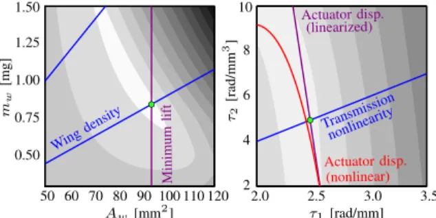
50 60 70 80 90 100 110 120 0.50 0.75 1.00 1.25 1.50 2.0 2.5 3.0 3.5 2 4 6 8 10 Wing density Minimum lift Transmission Actuator disp. Actuator disp. τ1[rad/mm] Aw[mm2] m w [mg] τ2 [rad/mm 3] nonlinearity (linearized) (nonlinear)
Fig. 2. Visualization of two slices of the parameter space with objective contours (lower cost is shaded lighter) and labeled constraint boundaries (text is on the feasible side of the bold curves).
a) Actuator displacement limit: The strain limit of the piezoelectric bimorphs |qact| ≤ q¯act are an important
constraint on the output strokeφ. Without loss of generality (τis odd), we first considerqa>0, and define the maximum output stroke amplitude in the input trajectory asq¯a. Using (11), at each output stateq, we can express this constraint in terms of the coefficients asχ(τ1, τ2) :=τ−1(qa)≤qact,max.
We linearize this constraint at(τ10,0), whereτ10:= ¯qa/q¯act
would be the requiredτ1 for a linear transmission, to get
Dτχ· τ1−τ10 τ2 ≤0⇒τ2≥ 3¯qa ¯ qact · ∂χ ∂τ1 (τ1−τ10). (25)
As shown in Fig.2(right), this linearization is a conservative sufficient condition for remaining within displacement limits. b) Wing density: Wing material density is an important material constraint on the wing inertia relative to its area [8]. We approximate that our single inertial parametermw must be related to the wing area asAwρmin≤mw≤Awρmax.
c) Wing aspect ratio: Following observations in [10], we constrain the aspect ratioARminc¯2≤Aw≤ARmax¯c2.
d) Transmission nonlinearity: Relating the mechanism design of the SDAB transmission [18] to the polynomial coefficients of (3), we anecdotally find that it is possible to find mechanism link lengths up to a certain ratio ofτ2/τ1
(see also Fig.4). So, we add a constraint0≤τ2≤τˆmaxτ1.
e) Minimum lift: In order to “scale” designs or require them to hover with different payloads, we can apply a minimum lift constraint which approximately maps on to the parameter space. With fixed wing stroke and pitch kinematics (and lift coefficients), the lift approximately scales asAw/δ [8]. Thus, the initial trajectory and parameter set can provide a lower bound on this ratio of parameters, Aw ≥αminliftδ. Note that though all the resulting optimal designs do not perfectly satisfy this approximate scaling relation due to the impact of other constraints and imperfect resonance conditions, the attained lift is typically within a few percent of the requested value. We apply this strategy to cover the space of available designs in Fig.4C.
B. Dynamic Model
We follow and build upon extensive prior literature mod-eling the design in Fig. 1 [16], [7], [10], while remaining within the general framework ofII-A.
1) Kinematics: The output configuration isq= (φ, ψ)∈ Q:=S2, whereφis the output stroke position, andψis the angle of the passive hinge. In agreement withII-Aand (3), theφ-DOF is actuated through a transmission.
2) Aerodynamics: In this paper we assume that there is no external wind, and the aerodynamic forces are modeled with the blade-element method. As shown in [16, (2.22)], the lift and drag forces depend on the wing shape parametersrˆiand geometry fromIII-A.1, the density of the medium, and φ˙2
(quadratic in velocity as asserted inII-B). In (2),J := Dqpcp,
andF is the sum of the lift and drag forces.
3) Dynamics: We use a Lagrangian dynamic model (2) including the wing energy components of (24). The potential energy (other than the reflected actuator stiffness II-A.3) includes the transmission and hinge flexure stiffnesses
γ(q) := 12(kφφ2+kψψ2). (26) The non-Lagrangian terms include damping in the hinge as described inIII-A.2.
IV. RESULTS
A. Algorithm Performance Characterization
1) Parameter space visualization: Fig.2shows the result of a single design optimization with the SDAB actuator (no force limit imposed), requesting 180mg lift, where we have visualized two slices of the parameter space with contours of the objective function, along with bold lines depicting labeled constraint boundaries, and a dot at the selected design. The non-convexity of the objective function is apparent from the contours on the left, and we also see that (in this instance, and typically) active constraints include wing density, minimum lift, transmission nonlinearity, and actuator displacement.
2) Validation against simplified scaling: To test if our solution method can provide globally feasible solutions, we compare its output at a variety of operating points against some predictions of a simplified scaling model. To do so, we first establish two identities that are satisfied by all designs satisfying simplified scaling assumptions:
Assuming at-resonance operation with a linear transmis-sion of ratio T, operation at peak actuator force u¯act and
peak actuator displacement q¯act, the peak drag force must
be supplied by the actuatorFD =T−1u¯actL−w1. Assuming ideal flapping kinematics can be maintained (fixed lift/drag ratio), FL∝FD= ¯ qactu¯actL−w1 ¯ qactT ∝mact` −1, (27)
wheremact ∝qactuact elaborates the fact that the product
qactuact is proportional to the volume of piezoelectric
ma-terial in the actuator, and we define ` := LwTq¯act as the
arc length swept by the wings. The peak mechanical power consumption (closely related to “real input power” [8]) can be calculated in the actuator frame asPmech= ¯uact(¯qactf)
(the latter term is the peak stroke velocity). At resonance,
Pmech≈(T FaeroLw)·q¯actf ≈Faero`f (27)
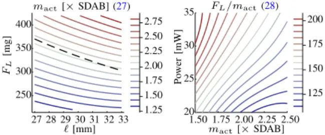
27 28 29 30 31 32 33 250 300 350 400 1.25 1.50 1.75 2.00 2.25 2.50 2.75 1.50 1.75 2.00 2.25 2.50 20 25 30 35 125 150 175 200 mact[×SDAB] (27) FL/mact(28)
FL [mg] Po wer [mW] `[mm] mact[×SDAB]
Fig. 3. Validation of algorithm results (contours) against (dashed) scaling predictions (IV-A.2).
We conclude that increasingf inescapably increases power consumption (28), while from (27), increasedf with smaller wings (i.e. smaller `) may be a route to increasing mass-specific liftFL/mact. We empirically demonstrate this
trade-off in Sec.IV-C.3, but first we numerically test our algorith-mic design tool for the satisfaction of identities (27), (28).
In Fig. 3, on the left we plot mact as defined above
corresponding to optimal designs for a range of operating conditions and note that the contours match quite closely the `−1 prediction of simplified scaling (dashed line at one
mact). On the right, we show that for a given actuator and
power budget, higher mass-specific lift can be found to the top left (invariably, also costing more power). In both of these cases, the algorithm found an optimal design satisfying all parameteric constraints and leveraging the nonlinear trans-mission (neither of which were considered in the simplified scaling predictions in (27), (28)).
B. Nonlinear Transmission
As motivated in the introduction, the algorithm presented here can automatically reason about more complicated dy-namics than conventional design methodologies allow for. In this section we introduce a novel nonlinear transmission that allows for variable EMA through the wingstroke. Intuitively, at resonance, the required output force peaks at mid-stroke, when the leading edge velocity is highest. This suggests that to reduce peak actuator force, the EMA should be highest at midstroke. On the other hand, in order to attain the maximum stroke angle possible, we would like a high displacement amplification near end-stroke. However, importantly, it is not straightforward to predict the effect such a change would have on the passive dynamics, since the reflected actuator stiffness also changes within stroke precluding direct application of conventional scaling-based design (IV-A.2).
1) Design implementation: The RoboBee transmission converts approximately linear actuator tip motion to rota-tional motion of the wing through a slider-crank-like mecha-nism [18] (Fig.1). Parallel mechanism design is beyond the scope of this paper, so instead, we manually adjust the link lengths to approximate the cubic polynomial model of (4).
Fig. 4A shows overlaid snapshots of a top-view of the transmission showing approximately symmetric output at actuator positions between ±0.3 mm in increments of 0.15 mm. As suggested by the optimization, we select coefficients
τ1 = 1.8, τ2 = 3.6 and select the mechanism link lengths
l1 = 0.5, l2 = 0.8, l3 = 0.55, all in units of mm. Panel
B shows the actual (blue) infinitesimal kinematics of the mechanism compared to the idealized (green) behavior of (4), as well as the linear (yellow) version with τ2= 0.
2) Implications on vehicle design: While our algorithm automatically selects the optimal design, in this section we present some exhaustive numerical work to quantify the benefit of the added flexibility afforded byτ2 in (4).
Fig. 4C first shows a scatter plot showing the actuator-mass-specific liftFL/mact as the nonlinearity in the
trans-mission (horizontal axis,τˆmax inIII-A.3.d) and the
approxi-mate ratio of output stiffness to total stiffness in the system, ˜
kφ:=kφ/(kφ+kact/τ12), (29)
are varied. Each data point is an optimal design, with limits onτˆ2(III-A.3.d) andkφ supplied as inputs.
The first observation we make here is that over a range of desired lift conditions (180–400mg) and over 1500 designs, the resulting performance appears to lie on a 2-dimensional submanifold, suggesting that the implicit definition of this submanifold may be another invariant of optimal designs.10 The second observation is that at sufficiently high ˜kφ, the nonlinearity in the transmission enables a large benefit, whereas the advantage is more modest at lowerk˜φ (system stiffness is dominated by the reflected actuator stiffness).
PanelDshows a comparison of the predicted mass-specific lift and mechanical power consumption attained with τ2 ≤
2τ1compared to an optimal design withτ2constrained to be
0. The horizontal axis shows different optimization weights in (20) to demonstrate how the optimization can trade off these two design objectives. We can conclude that in general, the specific lift11 is always greater with the transmission allowed the extra freedom τ2 > 0 (with gains of over
10% in some cases), and power consumption is better or worse depending on the weighting used in the objective. Future work will investigate the specific input force patterns responsible for the trends visible here.
C. Application to FWMAV Vehicle Design
In this section we present static testing experimental results with the SDAB actuator, for which the airframe is held fixed, and an open-loop “flattened sine” signal [8] is sent to the actuator at a given voltage and frequency. Despite the control signal being open-loop, the resulting tuned wing kinematics correspond closely to the sinusoidal input trajectories used to seed our design optimization. We summarize the optimization-guided modifications we have implemented on the SDAB and BigBee designs in TableI.
10The intuitive interpretation of this is that with sufficient freedom in
vehicle design (III-A), the aerodynamic work done is only constrained by the actuator, until the output stiffnesskφdominates. In the latter case (compared
to the identical design with smallerkφ), the stroke resonance condition will
occur at a lower operating frequency, thus lowering the produced lift. Analytically locating this design manifold (especially with the transmis-sion nonlinearity) to mirrorIV-A.2would be challenging, further motivating the need for an algorithmic design process as explored here.
11the actuator force appears in the actuator mass (27), but the required
0.3- 0.2- 0.1 0.1 0.2 0.3 - 0.6 - 0.4 - 0.2 0.2 0.4 0.6 0.3- 0.2- 0.1 0.1 0.2 0.3 1.85 1.90 1.95 2.00 2.05 2.10 τ(qact) qact Dτ(qact) l2 l1 l3 A B l3 l1 l2 0123 0.5 0.6 0.7 1.5 2.0 2.5 3.0 3.5 0 1 2 3 0.5 0.6 0.7 1.5 2.0 2.5 3.0 FL/mact ˆ τmax C ˆ τmax ˜ kφ ˜ kφ D A vg Po wer [mW] Lift / m act [ ] Power weighting (20) Nonlinear Linear
Fig. 4. Nonlinear transmission.Mechanism design and physical instantiation for the nonlinear transmission(A)and its infinitesimal kinematics(B).C
shows contours of performance (force-specific average lift) demonstrating performance benefits with transmission nonlinearity, andDshows individual normalized stroke curves comparing the linear and nonlinear transmissions in otherwise identical vehicle designs.
TABLE I
SUMMARY OF VEHICLE DESIGN SPECIFICATIONS
SDAB [7] Modified BigBee [6] Modified
Lw [mm] 17 17, 18.4 25.5 16.9, 24.2
Aw[mm2] 54.4 54.4 179 64.4, 107.3
τ1 [rad/mm] 2.666 1.8 3.28
-τ2 [rad/mm3] 0 3.6 0
-1) SDAB nonlinear transmission, high AR wing: We incorporated the optimization-suggested nonlinear transmis-sion into the SDAB design. On this chassis, we test the SDAB wing, as well as a modified wing with the same wing area, but with a 10% largerLw, 10% smaller¯c, and a 50%-thickened wing leading edge spar to increase stiffness against span-wise wing deformation at higher AR [10].
The top row of Fig. 5 shows the normalized stroke performance of the modified SDAB chassis (solid/dotted lines) compared to the original SDAB design (dashed lines) for the two wing designs considered here. The three voltages presented in each case demonstrate the general trend with voltage, and the highest voltage shown corresponds to the observed peak in voltage-normalized stroke. For simplicity, we have not included the wing pitching dynamics in this plot, but rather examine full wing kinematics in the next section. The “original SDAB” data presented here are from trials with the best recorded performance of the SDAB design over several instantiations. We make the following observations:
In the case of the higher-aspect ratio wing (top right panel) the original transmission is unable to drive the stroke at any reasonable velocities to sufficiently excite the wing pitching dynamics due to its increasedIzz, whereas the new transmission is capable of doing so at generally lower volt-ages. Intuitively, the increased force-production at midstroke allows the nonlinear transmission to support higher-inertia wings. To gauge lift production and power consumption, in Fig. 6 (left) we have plotted predicted (see caption) lift and power for the new design compared to [7]. Among the set of wings and hinges tested (not fine-tuned), the stiffer hinge attained the best lift/drag ratios at resonance. At 150V, the lift and power are both slightly lower than the original design, while at 190V, the lift is about 22% higher and the power consumption is 50% higher. However, at 190V, the actuator displacement exceeded the 0.3mm safe limit.
25 50 75 100 125 150 175 0.2 0.3 0.4 0.5 0.6 0.7 Freq [Hz] 120 150 180 210 0.2 0.3 0.4 0.5 Freq [Hz] 75 100 125 150 175 200 225 Freq [Hz] Normalized strok e [ ◦/V] 180V 150V 120V Original actuator, wing
Original data [6] New medium wing New small wing
Normalized strok e [ ◦/V] 200V 150V 200V 150V 200V 180V 150V BigBee 190V 160V 120V 180V 180V 120V 150V 190V 140V 120V 190V 150V 120V Modified
Original Modified non-stiff
Original Modified stiff
SDAB, regular wing SDAB, higher aspect ratio wing
Fig. 5. Top:Voltage-normalized stroke for the modified vehicle design of Fig.1(solid lines) compared to the standard SDAB design (dashed lines) for the regular (left) and high AR (right) wings.Bottom:Normalized stroke plots for different sets of wings on the BigBee platform along with stroke kinematics snapshots with the original and a new medium wing. Detailed specifications for each design are listed in TableI.
In summary, while the performance is promising, further fine-tuning is required to realize the 10% performance gains found numerically (Fig.4D).
2) BigBee force-power tradeoffs: With the BigBee plat-form, we demonstrate the possibility of trading off force and power requirements as numerically demonstrated in Fig. 3, as well as the applicability of the optimization algorithm to different design scales and objectives. We used our opti-mization algorithm to return optimal designs with actuator mass and transmission roughly matching [18], while varying the weights in (20). We have preserved all components of the original design with the exception of the wing and wing hinge. In the bottom row of Fig. 5, dashed lines indicate the original design. However, while the rightmost cluster of dashed lines have been reproduced from data in [6], the
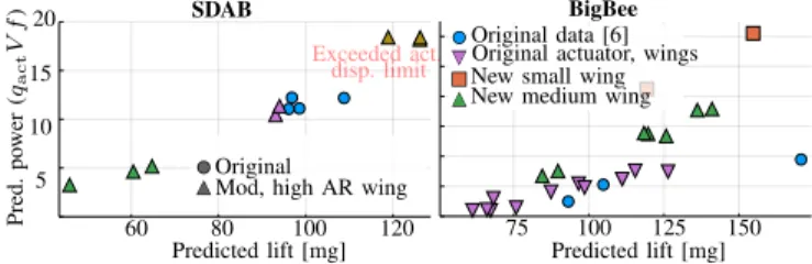
60 80 100 120 5 10 15 75 100 125 150 Pred. po wer ( qact V f ) Predicted lift [mg] Original
Mod, high AR wing
Predicted lift [mg] 20
New small wing New medium wing Original data [6] Original actuator, wings
SDAB BigBee
Exceeded act. disp. limit
Fig. 6. Calculated model-predicted lift (unnormalized in theleftcolumn and voltage-normalized in therightcolumn) vs. power consumption for the design modifications inIV-Cin comparison to their original counterparts, the SDAB platform (top row) and the BigBee platform (bottom row). The original SDAB data plotted here and in Fig.5correspond to its best recorded performance, while the custom actuators in the modified SDAB vehicle (only one of which has been built) likely do not perform optimally.
leftmost cluster contains new data from a different BigBee actuator: the performance discrepancy can be attributed to manufacturing variance or degradation over time. All other data on this plot are also from this latter actuator, allowing us to explore force-power tradeoffs enabled by wing design choice. Comparing the (left) dashed lines with the dotted and solid clusters, we can see that smaller wings (a result of lower wyu (20)) can enable higher stroke amplitudes at higher flapping frequencies with the otherwise same vehicle at the expense of higher power consumption (discussed next). 3) Lift and power: From our static testing results in the previous subsection, we select the operating conditions with close-to-ideal wing kinematics (zero pitch phase or slightly advanced pitch as defined in [9, Fig. 1]), and extract the wing pitch amplitude for those trials. Fig.6shows a scatter plot of the model-predicted lift and power consumption12 at a variety of operating voltages for each design as estimated from the measured motion. In a regime of operating voltages, normalizing the lift by the square of the voltage allows for some insight into the vehicle design “efficiency” (bottom row). We can conclude from the left of Fig.6that even before much fine-tuning, the new transmission, wing, and hinge promise to endow the SDAB vehicle with approximately 30– 35% higher lift and voltage-normalized lift. On the right, we see that the smaller wings do indeed provide greater lift while consuming greater power. We also include the lift/power data from the original BigBee actuator from [18] (blue), showing that the even with the drastically reduced present actuator performance (other colors), it is possible to attain greater voltage-normalized lift at the expense of greater power consumption.
V. CONCLUSION
In this paper we presented a novel paradigm and algorithm for optimally designing underactuated robot platforms in 12The predicted lift is calculated using the kinematic q,q˙ data along
with known wing geometry Aw, Lw. The original SDAB data shown
was measured to provide 135mg lift per wing, but our model-predicted lift (consistently used across all data points) underestimates this lift by about 30%. The predicted power consumption is approximated from the stroke amplitude, input force amplitude, and operating frequency assumption resonance operation according to (28). We use these approximations instead of the full forward dynamics (Sec. III) in order to minimize reliance on (possibly incorrectly estimated) dynamical parameters. We assume that the wing shape parameters are roughly unchanged.
highly-constrained nonconvex parameter spaces. Future work includes the development of a problem-specific solver for the optimization problem, and application to manipulators, terrestrial robots, and other robotic platforms.
REFERENCES
[1] M. Yim, W.-M. Shen, B. Salemi, D. Rus, M. Moll, H. Lipson, E. Klavins, and G. S. Chirikjian, “Modular self-reconfigurable robot systems [grand challenges of robotics],”IEEE Robotics & Automation Magazine, vol. 14, no. 1, pp. 43–52, 2007.
[2] D. W. Haldane, M. M. Plecnik, J. K. Yim, and R. S. Fearing, “Robotic vertical jumping agility via series-elastic power modulation,”Science Robotics, vol. 1, no. 1, 2016.
[3] A. De, A. Stewart-Height, and D. E. Koditschek, “Task-Based Control and Design of a BLDC Actuator for Robotics,”IEEE Robotics and Automation Letters, vol. 4, no. 3, pp. 2393–2400, 2019.
[4] S. Ha, S. Coros, A. Alspach, J. Kim, and K. Yamane, “Joint Optimization of Robot Design and Motion Parameters using the Implicit Function Theorem,” inRobotics: Science and Systems XIII. Robotics: Science and Systems Foundation, July 2017.
[5] R. J. Full and D. E. Koditschek, “Templates and anchors: neuromechanical hypotheses of legged locomotion on land,”Journal of Experimental Biology, vol. 202, no. 23, pp. 3325–3332, Dec. 1999. [6] K. Y. Ma, P. Chirarattananon, and R. J. Wood, “Design and fabrication of an insect-scale flying robot for control autonomy,” in 2015 IEEE/RSJ International Conference on Intelligent Robots and Systems (IROS). Hamburg, Germany: IEEE, Sept. 2015, pp. 1558–1564.
[7] N. T. Jafferis, M. A. Graule, and R. J. Wood, “Non-linear resonance modeling and system design improvements for underactuated flapping-wing vehicles,” in2016 IEEE International Conference on Robotics and Automation (ICRA). Stockholm, Sweden: IEEE, May 2016, pp. 3234–3241.
[8] N. T. Jafferis, E. F. Helbling, M. Karpelson, and R. J. Wood, “Untethered flight of an insect-sized flapping-wing microscale aerial vehicle,”Nature, vol. 570, no. 7762, pp. 491–495, June 2019. [9] Y. Chen, N. Gravish, A. L. Desbiens, R. Malka, and R. J.
Wood, “Experimental and computational studies of the aerodynamic performance of a flapping and passively rotating insect wing,”Journal of Fluid Mechanics, vol. 791, pp. 1–33, Mar. 2016.
[10] Y. Chen, K. Ma, and R. J. Wood, “Influence of wing morphological and inertial parameters on flapping flight performance,” inIntelligent Robots and Systems (IROS), 2016 IEEE/RSJ International Conference on. IEEE, 2016, pp. 2329–2336.
[11] C. An, C. Atkeson, and J. Hollerbach, “Estimation of inertial parameters of rigid body links of manipulators,” in1985 24th IEEE Conference on Decision and Control. Fort Lauderdale, FL, USA: IEEE, Dec. 1985, pp. 990–995.
[12] R. H. Byrd and R. B. Schnabel, “Continuity of the null space basis and constrained optimization,”Mathematical Programming, vol. 35, no. 1, pp. 32–41, 1986.
[13] A. W¨achter and L. T. Biegler, “On the implementation of an interior-point filter line-search algorithm for large-scale nonlinear program-ming,”Mathematical programming, vol. 106, no. 1, pp. 25–57, 2006. [14] B. M. Finio, N. O. Perez-Arancibia, and R. J. Wood, “System identification and linear time-invariant modeling of an insect-sized flapping-wing micro air vehicle,” in 2011 IEEE/RSJ International Conference on Intelligent Robots and Systems. San Francisco, CA: IEEE, Sept. 2011, pp. 1107–1114.
[15] J. P. Whitney and R. J. Wood, “Conceptual design of flapping-wing micro air vehicles,” Bioinspiration & Biomimetics, vol. 7, no. 3, p. 036001, Sept. 2012.
[16] ——, “Aeromechanics of passive rotation in flapping flight,”Journal of Fluid Mechanics, vol. 660, pp. 197–220, Oct. 2010.
[17] N. Doshi, B. Goldberg, R. Sahai, N. Jafferis, D. Aukes, R. J. Wood, and J. A. Paulson, “Model driven design for flexure-based Microrobots,” in2015 IEEE/RSJ International Conference on Intelligent Robots and Systems (IROS). Hamburg, Germany: IEEE, Sept. 2015, pp. 4119–4126.
[18] K. Y. Ma, S. M. Felton, and R. J. Wood, “Design, fabrication, and modeling of the split actuator microrobotic bee,” in 2012 IEEE/RSJ International Conference on Intelligent Robots and Systems. Vilamoura-Algarve, Portugal: IEEE, Oct. 2012, pp. 1133–1140.
![Fig. 1. The sources of experimental data in this paper are two variants of the RoboBee: BigBee [6] A, and the latest iteration of the split dual-actuator bee (SDAB) [7] B](https://thumb-us.123doks.com/thumbv2/123dok_us/9074042.2398211/1.918.472.839.232.480/sources-experimental-variants-robobee-bigbee-latest-iteration-actuator.webp)