© Center for Energy Economics
LNG SAFETY AND SECURITY
Michelle Michot Foss, Ph.D.
Chief Energy Economist and CEE Head
1801 Allen Parkway
Houston, Texas 77019
Tel 713-654-5400 Fax 713-654-5405
[email protected]
www.beg.utexas.edu/energyecon/lng
June 2012
Table of Contents
Executive Summary ... 5
Introduction ... 8
Safety Considerations in LNG Operations ... 9
LNG Properties and Potential Hazards ... 12
LNG Properties ... 12
Types of LNG Hazards ... 17
How Is a Safe, Secure LNG Value Chain Achieved? ... 20
Brief Overview of the LNG Value Chain ... 21
The LNG Value Chain in the U.S. and North America ... 21
Application of Safety Conditions to the LNG Value Chain ... 29
Conclusions ... 45
Appendix 1: Descriptions of LNG Facilities ... 48
Appendix 2: LNG Regulations ... 53
Appendix 3: Who Regulates LNG in the U.S.? ... 56
Onshore/Marine ... 56
Offshore ... 56
Federal Regulation of LNG ... 57
The Department of Energy (DOE) ... 57
The Federal Energy Regulatory Commission (FERC) ... 57
The Department of Transportation (DOT) ... 58
The U.S. Coast Guard (USCG) ... 59
The U.S. Environmental Protection Agency (EPA) ... 59
State regulation of LNG... 59
Non-Governmental Regulation of LNG ... 60
Appendix 4: Risk Perception ... 62
Terrorism ... 62
Earthquakes ... 63
Maritime Incidents ... 64
Operational Incidents ... 65
Appendix 5: Major LNG Incidents ... 66
Cleveland, Ohio, 1944 ... 68
Staten Island, New York, February 1973 ... 69
Cove Point, Maryland, October 1979 ... 70
LNG Vehicle Incidents ... 70
Appendix 6: Glossary of Terms ... 75
Appendix 7: Conversion Table ... 77
List of Figures and Tables
Figures
Figure 1. Continuous Improvement of LNG Safety, Environmental, and Security Infrastructure ... 9Figure 2. Critical Safety Conditions ... 10
Figure 3. Flammable Range for Methane (LNG) ... 14
Figure 4. Summary Comparison of LNG and Other Fuels ... 17
Figure 5. LNG Value Chain ... 21
Figure 6. LNG Liquefaction Export Facility in Kenai, Alaska ... 22
Figure 7. A Peak Shaving Facility ... 24
Figure 8. Typical LNG Receiving Terminal/Re-gasification Facility ... 24
Figure 9. The Energy Bridge™ System ... 25
Figure 11. U.S. LNG Facilities Storage Capacity ... 28
Figure 12. U.S. Regional LNG Storage Deliverability ... 29
Figure 13. Conceptual Design of Storage Tanks ... 30
Figure 14. Single Containment Tanks ... 31
Figure 15. A Spherical Tank ... 32
Figure 16. LNG Lagos - Membrane Type LNG Carrier ... 32
Figure 17. Double Containment Tanks ... 34
Figure 18. Full Containment Tanks ... 35
Figure 19. Tank Section of a Spherical Moss Design ... 36
Figure 20. Example Safety Zone: Cove Point ... 39
Figure 21. LNG Jetty with Unloading Arms - ALNG ... 48
Figure 22. Underground LNG tank: T-2 tank at Fukukita station of Saibu Gas Co., Ltd. ... 50
Figure 23. In pit LNG storage tank ... 50
Figure 24. Open Rack Vaporizer ... 51
Figure 25. Seven Submerged Combustion Vaporizers, Lake Charles, La., Terminal ... 52
Figure 26. U.S. LNG Regulators ... 56
Figure 27. LNG incidents before and after 1985 by ship type ... 65
Figure 28. Energy accident fatalities by source, 1907–2007 ... 68
Tables
Table 1. Comparison of Properties of Liquid Fuels ... 14Table 2. Autoignition Temperature of Liquid Fuels ... 16
Table 3. LNG Facilities in the U.S. and Japan... 64
Table 4. Major Energy-related Incidents Worldwide, 1907-2007 ... 66
LNG SAFETY AND SECURITY
1EXECUTIVE SUMMARY
This briefing paper is the second in a series that describes the liquefied natural gas (LNG) industry and the increasingly important role that LNG may play in the nation’s energy future. The first paper, Introduction to LNG, briefs the reader on LNG and touches on many of the key issues related to the LNG industry. This paper’s first edition came out in October 2003 and deals with safety and security aspects of LNG operations. A third paper, The Role of LNG in North American
Natural Gas Supply and Demand, followed in September 2004. All of these
reports, with supplemental information, were compiled in a complete online fact book, Guide to LNG in North America, www.beg.utexas.edu/energyecon/lng. LNG has been transported and used safely in the U.S. and worldwide for roughly 40 years. The U.S. has three types of LNG facilities: LNG export, LNG import, and LNG peaking facilities. The U.S. has the largest number of LNG facilities in the world, scattered throughout the country and located near population centers where natural gas is needed.
The LNG industry has an excellent safety record. This strong safety record is a result of several factors. First, the industry has technically and operationally evolved to ensure safe and secure operations. Technical and operational advances include everything from the engineering that underlies LNG facilities to operational procedures to technical competency of personnel. Second, the physical and chemical properties of LNG are such that risks and hazards are well understood and incorporated into technology and operations. Third the standards, codes, and regulations that apply to the LNG industry further ensure safety. While we in the U.S. have our own regulatory requirements for LNG operators, we have benefited from the evolving international standards and codes that regulate the industry. This report defines and explains how LNG safety and security is achieved, based on our extensive review of technical and operational data.
Safety in the LNG industry is ensured by four elements that provide multiple layers of protection both for the safety of LNG industry workers and the safety of communities that surround LNG facilities. Primary Containment2 is the first and
most important requirement for containing the LNG product. This first layer of protection involves the use of appropriate materials for LNG facilities as well as proper engineering design of storage tanks onshore and on LNG ships and elsewhere.
1 This publication was supported by a research consortium, Commercial Frameworks for LNG in
North America. Sponsors of the consortium were BP Energy Company-Global LNG, BG LNG Services, ChevronTexaco Global LNG, Shell Gas & Power, ConocoPhillips Worldwide LNG, El Paso Global LNG, ExxonMobil Gas Marketing Company, Tractebel LNG North America/Distrigas of Massachusetts. The U.S. Department of Energy-Office of Fossil Energy provides critical support and the Ministry of Energy and Industry, Trinidad & Tobago participates as an observer. The report was prepared by CEE researchers Michelle Michot Foss, Fisoye Delano, Gürcan Gülen, and Dmitry Volkov. Peer reviews were provided by university faculty colleagues and outside experts.
Secondary containment ensures that if leaks or spills occur at the onshore LNG facility, the LNG can be fully contained and isolated from the public.
Safeguard systems offers a third layer of protection. The goal is to minimize the frequency and size of LNG releases both onshore and offshore and prevent harm from potential associated hazards, such as fire. For this level of safety protection, LNG operations use technologies such as high level alarms and multiple back-up safety systems, which include Emergency Shutdown (ESD) systems. ESD systems can identify problems and shut off operations in the event certain specified fault conditions or equipment failures occur, and which are designed to prevent or limit significantly the amount of LNG and LNG vapor that could be released. Fire and gas detection and fire fighting systems all combine to limit effects if there is a release. The LNG facility or ship operator then takes action by establishing necessary operating procedures, training, emergency response systems, and regular maintenance to protect people, property, and the environment from any release. Finally, LNG facility designs are required by regulation to maintain separation distances to separate land-based facilities from communities and other public areas. Safety zones are also required around LNG ships.
The physical and chemical properties of LNG necessitate these safety measures. LNG is odorless, non-toxic, non-corrosive, and less dense than water. LNG vapors (primarily methane) are harder to ignite than other types of flammable liquid fuels. Above approximately -110oC LNG vapor is lighter than air. If LNG spills on the ground or on water and the resulting flammable mixture of vapor and air does not encounter an ignition source, it will warm, rise, and dissipate into the atmosphere. Because of these properties, the potential hazards associated with LNG include heat from ignited LNG vapors and direct exposure of skin or equipment to a cryogenic (extremely cold) substance. LNG vapor can be an asphyxiant. This is also true of vapors of other liquid fuels stored or used in confined places without oxygen.
There is a very low probability of release of LNG during normal industry operations due to the safety systems that are in place. Unexpected large releases of LNG, such as might be associated with acts of terrorism, bear special consideration although the consequences may well be similar to a catastrophic failure. In the case of a catastrophic failure, emergency fire detection and protection would be used, and the danger to the public would be reduced or eliminated by the separation distances of the facility design. LNG operations are industrial activities, but safety and security designs and protocols help to minimize even the most common kinds of industrial and occupational incidents that might be expected. LNG contains virtually no sulfur; therefore the combustion of re-gasified LNG used as fuel has lower emissions of air contaminants than other fossil fuels. In crude oil producing countries, as a general move towards lessening the environmental impact of oil production, a larger percentage of the associated natural gas is being converted to LNG instead of being flared. In many instances, this choice reduces the environmental impact of the continuous flaring of large quantities of natural gas, while also capturing this valuable resource for economic use. Thus, LNG development can have significant environmental and economic benefits.
Importantly, the properties associated with LNG and the safety and security practices and regulatory oversight embedded in the industry system apply no matter what type of facility or end use. This paper focuses on LNG storage facilities that are associated with natural gas pipeline and utility operations and services, as well as the crucial infrastructure that comprises the global LNG “supply” or “value” chains. Demand for natural gas, in the form of LNG, is emerging and growing in the U.S., North America, and worldwide. Transportation constitutes one of the more quickly developing applications. LNG is used as fuel for regional and long haul trucking, truck operations at ports and harbors, railroads, and marine shipping (ferries and the like, as well as LNG ship operations). These uses require dispersed storage and distribution networks that, along with traditional satellite and peak-shaving facilities, can serve customers while meeting all safety and security requirements.
Our review of the LNG industry safety and technological record, engineering design and operating systems and the standards and regulations that governing the design, operation and location of LNG facilities indicates that LNG can be safely transported and used in the U.S. and North America so long as safety and security standards and protocols developed by the industry are maintained and implemented with regulatory supervision. Our LNG web site,
http://www.beg.utexas.edu/energyecon/lng/, provides links to other industry,
INTRODUCTION
LNG has been transported and used safely in the U.S. and worldwide for roughly 40 years. The U.S. has the largest number of LNG facilities in the world, scattered throughout the country and located near population centers where natural gas is needed. Our analysis of data on LNG safety and security indicates an excellent safety record. This strong safety record is a result of several factors. First, the industry has technically and operationally evolved to ensure safe and secure operations. Technical and operational advances include everything from the engineering that underlies LNG facilities to operational procedures to technical competency of personnel. Second, the physical and chemical properties of LNG are such that risks and hazards are easily defined and incorporated into technology and operations. Third, a broad set of standards, codes, and regulations applies to the LNG industry to further ensure safety. These have evolved through industry experience worldwide and affect LNG facilities and operations everywhere. Regulatory compliance provides transparency and accountability. This report defines and explains how LNG safety and security is achieved, based on our extensive review of technical and operational data. Our conclusion is that LNG can continue to be transported, stored, and used safely and securely, as long as safety and security standards and protocols developed by the industry are maintained and implemented with regulatory supervision. It is in the best interest of the industry, regulators, and the general public that this goal be achieved so that the benefits of natural gas can be realized for consumers.
By converting natural gas to LNG, it can be shipped over the oceans and great distances from the countries where it is produced to those where it is in demand. Natural gas is used in homes for cooking and heating, in public institutions, in agriculture, by industry and to generate electric power. Natural gas is important not only as a clean source of energy, but also as a feedstock for the petrochemical industry to produce plastics, fibers, fertilizers, and many other products.
In this briefing paper, we discuss safety and security aspects of LNG. To prepare this report, we examined information on the physical properties of LNG, the safety record of LNG facilities and ships, the impact of the LNG operations on the environment and regulations and agencies concerned with safety and
environmental protection in the LNG industry. Members of our team have visited LNG facilities in the U.S. and Japan. From this comprehensive review, we have concluded that LNG has been and can continue to be used safely. As shown in Figure 1 below, there is a continuous improvement of LNG safety, environmental and security infrastructure. This report outlines technologies, strategies, recommendations, and key considerations employed by the LNG industry, and by regulators and public officials charged with public safety and security.
Figure 1. Continuous Improvement of LNG Safety, Environmental,
and Security Infrastructure
SAFETY CONSIDERATIONS IN LNG OPERATIONS
In order to define LNG safety, we must ask: When is LNG a hazard? The LNG industry is subject to the same routine hazards and safety considerations that occur in any industrial activity. Risk mitigation systems must be in place to reduce the possibility of occupational hazards and to ensure protection of surrounding communities and the natural environment. As with any industry, LNG operators must conform to all relevant national and local regulations, standards, and codes. Beyond routine industrial hazards and safety considerations, LNG presents specific safety considerations. In the event of an accidental release of LNG, the safety zone around a facility protects neighboring communities from personal injury, property
Industry Standards Regulations Industry Experience and Training Design/Technology Safety, Security, Environmental Integrity
damage, or fire. The one and only case of an accident that affected the public was in Cleveland, Ohio in 1944 (See Table 4). Research stemming from the Cleveland incident has influenced safety standards used today. Indeed, during the past four decades, growth in LNG use worldwide has led to a number of technologies and practices that will be used in the U.S. and elsewhere in North America as the LNG industry expands.
Generally, multiple layers of protection create four critical safety conditions, all of which are integrated with a combination of industry standards and regulatory
compliance, as shown in Figure 2.
Figure 2. Critical Safety Conditions
PRIMARY CONTAINMENT
SECONDARY CONTAINMENT
SAFEGUARD SYSTEMS
SEPARATION DISTANCE
INDUSTRY STANDARDS/REGULATORY COMPLIANCE
Industry standards are written to guide industry and also to enable public officials to more efficiently evaluate safety, security, and environmental impacts of LNG facilities and industry activities. Regulatory compliance should ensure transparency and accountability in the public domain.
The four requirements for safety – primary containment, secondary containment,
safeguard systems and separation distance – apply across the LNG value chain,
from production, liquefaction, and shipping, to storage and re-gasification. (We use the term “containment” in this document to mean safe storage and isolation of LNG.) Later sections provide an overview of the LNG value chain and the details associated with the risk mitigation measures employed across it.
Primary Containment. The first and most important safety requirement for the industry is to contain LNG. This is accomplished by employing suitable materials
for storage tanks and other equipment, and by appropriate engineering design throughout the value chain.
Secondary Containment. This second layer of protection ensures that if leaks or spills occur, the LNG can be contained and isolated. For onshore installations dikes
and berms surround liquid storage tanks to capture the product in case of a spill.
In some installations a reinforced concrete tank surrounds the inner tank that normally holds the LNG. Secondary containment systems are designed to exceed the volume of the storage tank. As will be explained later, double and full
containment systems for onshore storage tanks can eliminate the need for dikes
and berms.
Safeguard Systems. In the third layer of protection, the goal is to minimize the release of LNG and mitigate the effects of a release. For this level of safety protection, LNG operations use systems such as gas, liquid and fire detection to rapidly identify any breach in containment and remote and automatic shut off
systems to minimize leaks and spills in the case of failures. Operational systems
(procedures, training and emergency response) also help prevent/mitigate hazards. Regular maintenance of these systems is vital to ensure their reliability.
Separation Distance. Federal regulations have always required that LNG facilities be sited at a safe distance from adjacent industrial, communities and other public areas. Also, safety zones are established around LNG ships while underway in U.S. waters and while moored. The safe distances or exclusion zones are based on LNG
vapor dispersion data, and thermal radiation contours and other considerations as
specified in regulations.
Industry Standards/Regulatory Compliance. No systems are complete without appropriate operating and maintenance procedures being in place and with insurance that these are adhered to, and that the relevant personnel are appropriately trained. Organizations such as the Society of International Gas Tanker and Terminal Operators (SIGTTO), Gas Processors Association (GPA) and National Fire Protection Association (NFPA) produce guidance which results from industry best practices.
The four conditions described above for safety, along with industry standards and regulatory compliance, are vital to continuing the strong LNG industry safety performance. They are essential if LNG is to play an increasing role in the U.S., both for energy security and to protect the flow of economic benefits from LNG to our society as a whole.
LNG PROPERTIES AND POTENTIAL HAZARDS
To consider whether LNG is a hazard, we must understand the properties of LNG and the conditions required in order for specific potential hazards to occur.
LNG Properties
Natural gas produced from the wellhead consists of methane, ethane, propane and heavier hydrocarbons, plus small quantities of nitrogen, helium, carbon dioxide, sulfur compounds, and water. LNG is liquefied natural gas. The liquefaction process first requires pre-treatment of the natural gas stream to remove impurities such as water, nitrogen, carbon dioxide, hydrogen sulfide and other sulfur compounds. By removing these impurities, solids cannot be formed as the gas is refrigerated. The product then also meets the quality specifications of LNG end users. The pretreated natural gas becomes liquefied at a temperature of approximately -256oF (-160oC) and is then ready for storage and shipping. LNG takes up only 1/600th of the volume required for a comparable amount of natural gas at room temperature and normal atmospheric pressure. Because the LNG is an extremely cold liquid formed through refrigeration, it is not stored under pressure. The common misperception of LNG as a pressurized substance has perhaps led to an erroneous understanding of its danger.
LNG is a clear, non-corrosive, non-toxic, cryogenic3 liquid at normal atmospheric pressure. It is odorless; in fact, odorants must be added to methane before it is distributed by local gas utilities for end users to enable detection of natural gas leaks from hot-water heaters and other natural gas appliances. Natural gas (methane) is not toxic. However, as with any gaseous material besides air and
oxygen, natural gas that is vaporized from LNG can cause asphyxiation due to lack of oxygen if a concentration of gas develops in an unventilated, confined area. The density of LNG is about 3.9 pounds per gallon, compared to the density of water, which is about 8.3 pounds per gallon. Thus, LNG, if spilled on water, floats on top and vaporizes rapidly because it is lighter than water.
Vapors released from LNG as it returns to a gas phase, if not properly and safely managed, can become flammable but explosive only under certain well-known conditions. Yet safety and security measures contained in the engineering design and technologies and in the operating procedures of LNG facilities greatly reduce these potential dangers.
The flammability range is the range between the minimum and maximum concentrations of vapor (percent by volume) in which air and LNG vapors form a flammable mixture that can be ignited and burn.
Figure 3 below indicates that the upper flammability limit and lower flammability
limit of methane, the dominant component of LNG vapor, are 5 percent and 15
percent by volume, respectively. When fuel concentration exceeds its upper flammability limit, it cannot burn because too little oxygen is present. This situation exists, for example, in a closed, secure storage tank where the vapor concentration is approximately 100 percent methane. When fuel concentration is below the lower flammability limit, it cannot burn because too little methane is present. An example is leakage of small quantities of LNG in a well-ventilated area. In this situation, the LNG vapor will rapidly mix with air and dissipate to less than 5 percent concentration.
Figure 3. Flammable Range for Methane (LNG)
A comparison of the properties of LNG to those of other liquid fuels, as shown in Table 1 below, also indicates that the Lower Flammability Limit of LNG is generally higher than other fuels. That is, more LNG vapors would be needed (in a given area) to ignite as compared to LPG or gasoline.
Table 1. Comparison of Properties of Liquid Fuels
Properties LNG
Liquefied Petroleum Gas
(LPG) Gasoline Fuel Oil
Toxic No No Yes Yes
Carcinogenic No No Yes Yes
Flammable Vapor
Yes Yes Yes Yes
Forms Vapor
Clouds Yes Yes Yes No
Asphyxiant Yes, but in a vapor
cloud Same as LNG Yes Yes
Extreme Cold Temperature
Yes Yes, if refrigerated No No Other Health
Hazards None None Eye narcosis, nausea, irritant, others
Same as gasoline
OVER RICH
Will Not Burn
Flammable
Too Lean - Will Not Burn
100%
Upper Flammability Limit, 15%
Lower Flammability Limit, 5%
0%
Properties LNG Petroleum Gas Liquefied
(LPG) Gasoline Fuel Oil Flash point4 (°F) -306 -156 -50 140 Boiling point (°F) -256 -44 90 400 Flammability Range in Air, % 5-15 2.1-9.5 1.3-6 N/A Stored
Pressure Atmospheric Pressurized (atmospheric if refrigerated)
Atmospheric Atmospheric
Behavior if
Spilled Evaporates, forming visible “clouds”. Portions of cloud could be flammable or explosive under certain conditions.
Evaporates, forming vapor clouds which could be flammable or explosive under certain conditions. Evaporates, forms flammable pool; environmental cleanup required. Same as gasoline
Source: Based on Lewis, William W., James P. Lewis and Patricia Outtrim, PTL, “LNG Facilities – The Real Risk,” American Institute of Chemical Engineers, New Orleans, April 2003, as modified by industry sources.
Methane gas will ignite only if the ratio or mix of gas vapor to air is within the limited flammability range. An often expected hazard is ignition from flames or sparks. Consequently, LNG facilities are designed and operated using standards and procedures to eliminate this hazard and equipped with extensive fire detection and protection systems should flames or sparks occur.
The autoignition temperature is the lowest temperature at which a flammable gas
vapor will ignite spontaneously, without a source of ignition, after several minutes of exposure to sources of heat. Temperatures higher than the autoignition temperature will cause ignition after a shorter exposure time. With very high temperatures, and within the flammability range, ignition can be virtually instantaneous. For methane vapors derived from LNG, with a fuel-air mixture of about 10 percent methane in air (about the middle of the 5-15 percent flammability limit) and atmospheric pressure, the autoignition temperature is above 1000°F (540°C). This extremely high temperature requires a strong source of thermal radiation, heat, or hot surface. If LNG is spilled on the ground or on water and the resulting flammable gas vapor does not encounter an ignition source (a flame or
4 "Flash point" means the minimum temperature at which a liquid gives off vapor within a test vessel in sufficient concentration to form an ignitable mixture with air near the surface of the liquid. OSHA 1910.106. http://www.ilpi.com/msds/ref/flashpoint.html
spark or a source of heat of 1000°F (540°C) or greater), the vapor will generally dissipate into the atmosphere, and no fire will take place.
When compared to other liquid fuels, LNG vapor (methane) requires the highest temperature for autoignition, as shown in the Table 2.
Table 2. Autoignition Temperature of Liquid Fuels
Fuel Autoignition Temperature, oF LNG (primarily methane) 1004 LPG 850-950 Ethanol 793 Methanol 867 Gasoline 495
Diesel Fuel Approx. 600
Source: New York Energy Planning Board, Report on issues regarding the existing New York Liquefied Natural Gas Moratorium, November 1998
Questions about LNG safety often demonstrate how LNG is confused with other fuels and materials. Our first briefing paper, Introduction to LNG, explains the differences between LNG and substances like liquefied petroleum gas (LPG), natural gas liquids (NGL). LNG is also quite different from gasoline, which is refined from crude oil. All of these fuels can be used safely as long as proper safety, security, and environmental protections are in place. In the U.S., we fill our cars and trucks with gasoline, use LPG (propane) in our backyard grills, and methane to heat our homes hundreds of millions of times each day, and serious safety incidents are rare. We can use both compressed natural gas (CNG) and LNG as transportation fuels. Natural gas can be converted to a middle distillate equivalent using Fischer-Tropsch; gas-to-liquids (GTL), while costly, would allow natural gas to flow directly into the petroleum value chain to provide transportation fuels and other products. All together, we transport and store all of these fuels and, again, safety and security incidents are rare.
Figure 4. Summary Comparison of LNG and Other Fuels
0 20 40 60 80 100 GTL LPG NGL CNG LNG % Methane Ethane Propane Butane Pentane Others (Carbon Dioxide, Nitrogen, C6+) Methanol or DME or Middle DistillatesIn summary, LNG is an extremely cold, non-toxic, non-corrosive substance that is transferred and stored at atmospheric pressure. It is refrigerated, rather than pressurized, which enables LNG to be an effective, economical method of transporting large volumes of natural gas over long distances. LNG itself poses little danger as long as it is contained within storage tanks, piping, and equipment designed for use at LNG cryogenic conditions. However, vapors resulting from LNG as a result of an uncontrolled release can be hazardous, within the constraints of the key properties of LNG and LNG vapors – flammability range and in contact with a source of ignition – as described above.
Types of LNG Hazards
5The potential hazards of most concern to operators of LNG facilities and surrounding communities flow from the basic properties of natural gas. Primary containment, secondary containment, safeguard systems, and separation distance provide multiple layers of protection. These measures provide protection against hazards associated with LNG.
5 Much of the material in this section is taken from the New York Energy Planning Board Report on
Explosion. An explosion happens when a substance rapidly changes its chemical state – i.e., is ignited – or is uncontrollably released from a pressurized state. For an uncontrolled release to happen, there must be a structural failure – i.e., something must puncture the container or the container must break from the inside. LNG tanks store the liquid at an extremely low temperature, about -256°F (-160°C), so no pressure is required to maintain its liquid state. Sophisticated containment systems prevent ignition sources from coming in contact with the liquid. Since LNG is stored at atmospheric pressure – i.e., not pressurized – a crack or puncture of the container will not create an immediate explosion.
Vapor Clouds. As LNG leaves a temperature-controlled container, it begins to warm up, returning the liquid to a gas. Initially, the gas is colder and heavier than the surrounding air. It creates a fog – a vapor cloud – above the released liquid. As the gas warms up, it mixes with the surrounding air and begins to disperse. The vapor cloud will only ignite if it encounters an ignition source while concentrated within its flammability range. Safety devices and operational procedures are intended to minimize the probability of a release and subsequent vapor cloud having an affect outside the facility boundary.
Freezing Liquid. If LNG is released, direct human contact with the cryogenic liquid will freeze the point of contact. Containment systems surrounding an LNG storage tank, thus, are designed to contain up to 110 percent of the tank’s contents. Containment systems also separate the tank from other equipment. Moreover, all facility personnel must wear gloves, face masks and other protective clothing as a protection from the freezing liquid when entering potentially hazardous areas. This potential hazard is restricted within the facility boundaries and does not affect neighboring communities.
Rollover. When LNG supplies of multiple densities are loaded into a tank one at a time, they do not mix at first. Instead, they layer themselves in unstable strata within the tank. After a period of time, these strata may spontaneously rollover to stabilize the liquid in the tank. As the lower LNG layer is heated by normal heat leak, it changes density until it finally becomes lighter than the upper layer. At that point, a liquid rollover would occur with a sudden vaporization of LNG that may be
too large to be released through the normal tank pressure release valves. At some point, the excess pressure can result in cracks or other structural failures in the tank. To prevent stratification, operators unloading an LNG ship measure the density of the cargo and, if necessary, adjust their unloading procedures accordingly. LNG tanks have rollover protection systems, which include distributed temperature sensors and pump-around mixing systems.6
Rapid Phase Transition. When released on water, LNG floats – being less dense than water – and vaporizes. If large volumes of LNG are released on water, it may vaporize too quickly causing a rapid phase transition (RPT).7 Water temperature and the presence of substances other than methane also affect the likelihood of an RPT. An RPT can only occur if there is mixing between the LNG and water. RPTs range from small pops to blasts large enough to potentially damage lightweight structures. Other liquids with widely differing temperatures and boiling points can create similar incidents when they come in contact with each other.
Sloshing. The advent of LNG offshore terminals implies certain risks associated with tanks only partially filled with LNG. Carrying LNG in partially filled tanks could lead to sloshing - a violent motion of the fluid. Sloshing could lead to an increased high pressure of LNG on the tank walls, especially in an abnormally harsh wave environment.8 Bureau Veritas and other classification societies have filling limitations for LNG cargo systems (see Table 3 below).
Table 3. Limitations for LNG cargo systems
System Filling Limitation
Membrane FL between 10%L-70/80%H not allowed
MOSS Without limits due to spherical geometry
IHI-SPB Possibility to arrange wash bulkheads
FL: filling level, L: length of the tank, H: height of the tank.
Source: Adapted from L. Delorme, A. Souto Iglesias and S. Abril Perez, “Sloshing Loads Simulation In LNG Tankers With SPH”. International Conference On Computational Methods In Marine Engineering, MARINE 2005
6 Welker J. R. and Sliepcevich C.M., Radiation, Heat Flux, and Overpressure in LNG Tanks, Proceedings of the International Conference on LNG Importation and Terminal Safety, Boston (1972).
7 Hashemi H.T., West H. H. and Sliepcevich C.M., LNG/Water Explosions: A Distributed Source, Proceedings of the 27th Annual Petroleum Mechanical Engineering Conference (1972).
8 Mateusz Graczyk, Torgeir Moan, “A probabilistic assessment of design sloshing pressure time histories in LNG tanks”. Ocean Engineering 35 (2008) 834–855.
Possible sloshing effect might require additional modifications to LNG cargo systems, especially taking into account increasing size of LNG carriers. Several engineering organizations, including Det Norske Veritas (DNV) and Norwegian Marine Technology Research Institute, have projects underway, researching this important safety issue.
Earthquakes and Terrorism. The unexpected risks of earthquakes and terrorism are discussed in Appendix 4: Risk Perception.
HOW IS A SAFE, SECURE LNG VALUE CHAIN ACHIEVED?
The LNG industry has operated worldwide for more than 40 years with very few safety incidents (see Appendix 5: Major LNG Incidents). In any major industry, there are certain hazards and risks associated with day-to-day operations, as well as definable risks and hazards associated with construction of facilities. This report does not deal with industrial workplace hazards or hazards associated with construction of major facilities. In the U.S. and elsewhere, policies and regulations at federal, state, and local levels of jurisdiction are in place to protect industrial workplace environments and construction sites and to minimize, and even eliminate, lost time due to accidents and injuries.
Our focus is on the properties of LNG, the particular hazards and risks that can develop from these properties and on the achievement of safety and security of LNG facilities. The major potential hazards of LNG and LNG vapors have been identified, analyzed, and taken into account, all to ensure the safe design, construction, operation, and maintenance and to prevent or mitigate the probability of these hazards. Prevention and mitigation steps are identified and implemented to reduce the probability of these hazards. Adherence to the regulations, codes, and operating practices makes the probability of an incident relating to such hazards extremely low. Much has been accomplished with respect to design and engineering of LNG facilities to address the risks and hazards associated with LNG. LNG facility design and engineering ensure that the experience is extended and safety record of the past 40 years continues into the future, so that society can reap the benefits of natural gas as a safe, clean fossil fuel.
Brief Overview of the LNG Value Chain
Our first briefing paper, Introduction to LNG, provides details on the global LNG value chain. The major components of the value chain include the following (see Figure 5):
Natural gas production, the process of finding and producing natural gas for
delivery to a processing facility.
Liquefaction, the conversion of natural gas into a liquid state so that it can be
transported in ships.
Transportation, the shipment of LNG in special purpose ships for delivery to
markets.
Re-gasification, conversion of the LNG back to the gaseous phase by passing the
cryogenic liquid through vaporizers.
Distribution and delivery of natural gas through the national natural gas pipeline system and distribution to end users.
Figure 5. LNG Value Chain
Gas
Field Liquefaction Facility LNG Storage Tank LNG Tanker LNG Storage Tank Vaporizers System/Market To Pipeline
Producing Region Consuming Region
Source: CMS Energy
Storage is a major focus for safety and security. Once natural gas is liquefied, it is
stored before shipment or loaded directly into the ship. LNG ships are required to have double hulls by regulation (International Maritime Organization) to facilitate safe transportation by sea. LNG receiving terminals and re-gasification facilities store LNG before it is re-gasified for pipeline transportation.
The LNG Value Chain in the U.S. and North America
The U.S. differs little from other countries that use LNG, with one significant exception: because LNG constitutes a relatively small proportion of the domestic natural gas supply base, LNG importation is not as familiar to the U.S. public as it is
in other countries. In addition, while widespread use of LNG satellite storage and peak shaving facilities has been made by pipelines and natural gas utilities, the public is generally not aware of these facilities. A great deal of LNG industry activity has taken place in the U.S. and North America since 2000. For the most part, that activity has centered on development of new LNG import terminals. These new facilities have benefitted from the expertise gained elsewhere regarding state-of-the-art materials and technologies used to construct LNG storage tanks for onshore receiving terminals, ideas for offshore receiving and re-gasification facilities, and new ship designs. This experience will be of benefit should some import capacity be converted to export U.S. domestic natural gas production. Second, operating practices at both existing and new LNG import facilities reflect knowledge gained from experience. Third, our regulatory framework benefits from the new technologies, materials, and practices that are being shared worldwide. Fourth, public education is critical for LNG and its properties to be better understood as use of LNG for end user needs like truck transportation rapidly grows.
Most LNG facilities in the U.S. are peak shaving liquefaction and storage facilities, satellite storage facilities or marine import terminals. Only one facility in the U.S. is a baseload liquefaction facility, the Kenai, Alaska liquefaction and export terminal.
Figure 6. LNG Liquefaction Export Facility in Kenai, Alaska
Baseload LNG liquefaction export facilities around the world take a natural gas feed
and pre-treat and refrigerate it until it becomes a liquid that can be stored at Source: ConocoPhillips
atmospheric pressure. These large processing facilities, consisting of one or more
LNG trains, include gas treatment facilities, liquefaction systems, storage tanks,
and LNG transfer terminals. The LNG liquefaction export facility located in Kenai, Alaska (as shown in Figure 6 above) currently is the only baseload liquefaction export facility in the U.S. LNG is exported to Japan; the Kenai to Tokyo Harbor route constituted the first Pacific Basin LNG trade route (see Introduction to
LNG). With new abundance in domestic natural gas supplies, additional
liquefaction export facilities are contemplated for the Lower 48 States and western Canada. Terminals that have capacity to both import and export conceivably could help balance the U.S. and North American natural gas marketplace. Currently, LNG imports remain an important component of the U.S. natural gas supply portfolio, especially for seasonal natural gas needs in locations like New England. U.S. and North American import terminals receive LNG from baseload liquefaction facilities in other countries. Natural gas from Canada could be sent to Lower 48 markets; natural gas from U.S. domestic production, including Alaska, could be shipped to U.S. receiving locations.9
Peak shaving LNG facilities, as shown in Figure 7 below, liquefy and store natural
gas produced during summer months for re-gasification and distribution during the periods of high demand, usually on cold, winter days. Peak shaving facilities use the same liquefaction processes as large baseload LNG facilities, but at a much smaller scale. In the case of peak shaving facilities, the natural gas feed is taken from the domestic pipeline system. In the U.S., local distribution companies (LDCs) have used LNG for peak shaving during high demand periods for more than 60 years. LNG peak shavers have provided secure and reliable supplies of natural gas for use during periods of peak demand.10
9 Section 27 (Jones Act) of the Merchant Marine Act of 1920 requires that all goods shipped in U.S. coastal waters between U.S. ports use U.S. flagged ships, constructed (or re-built) in the U.S., with U.S. ownership and maintenance and U.S. crews (citizens and permanent residents). Various attempts have been made to reform the Jones Act. The law was re-codified in 2006. See http://www.marad.dot.gov/documents/CabotageLaws.pdf and http://www.trans-inst.org/jones-act.html.
10 Cates, Rusty, International Gas Consulting, Inc., “LNG - Hedging Your Bets,” LNG: Economics & Technology Conference, January, 2003.
Figure 7. A Peak Shaving Facility
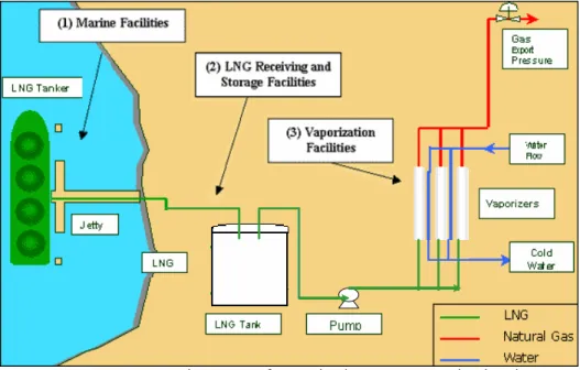
Perhaps most visible type of LNG facilities is baseload LNG receiving and
re-gasification facilities. These facilities consist of marine terminals for LNG ships (1),
LNG receiving and storage facilities (2), and vaporizing facilities and supporting utilities (3). Figure 8 provides a layout for typical onshore LNG baseload receiving facilities.
Figure 8. Typical LNG Receiving Terminal/Re-gasification Facility
Source: BP LNG. Note that type of vaporization process and related water requirements may vary. See Appendix 1: Descriptions of LNG Facilities for details.
Our first paper, Introduction to LNG, provides information on LNG facilities in the U.S. and North America. Onshore LNG terminals are reviewed and certified by the U.S. Federal Energy Regulatory Commission (FERC). For information on the FERC review process and facilities see
http://www.ferc.gov/industries/gas/indus-act/lng/exist-term.asp and
http://www.ferc.gov/industries/gas/indus-act/lng/LNG-existing.pdf. The FERC also has authority to certify any LNG export facilities.
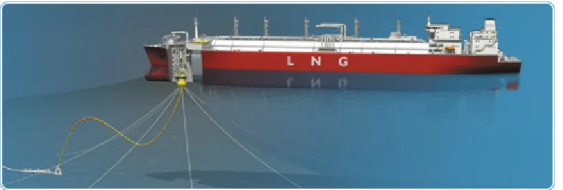
The majority of LNG import terminals are based onshore. In April 2005 Gulf Gateway Energy Bridge Deepwater Port11 (see Figure 9 below) was put into operation as the world’s first offshore liquefied natural gas (LNG) receiving facility and the first new LNG regasification facility in North America since 1980’s. Gulf Gateway was followed by Neptune and Northeast Gateway, both serving New England.
Figure 9. The Energy Bridge™ System
12The Energy Bridge™ System is based on specially designed Energy Bridge™ Regasification Vessels (EBRV). These are equipped with shipboard regasification equipment and are capable of docking with a submerged offloading buoy anchored offshore. When an EBRV reaches the buoy, it is retrieved and locked into a specially designed compartment within the ship. Once attached, the buoy serves as both the mooring system for the vessel and as the offloading mechanism for transferring the vaporous natural gas to the downstream pipeline.
After connecting to the STL Buoy, LNG is brought up to the required pipeline pressure
through onboard high-pressure pumps, and passed through a set of vaporizers,
11 Find out more about offshore projects in the CEE publication “LNG Offshore Receiving Terminals”. 12 See http://www.excelerateenergy.com/offshore-regasification-gateway
which turn the LNG back into vaporous natural gas. Natural gas is then discharged through the buoy into a flexible riser, through a subsea manifold and into a subsea pipeline for ultimate delivery to onshore markets. Following regasification and cargo discharge, the buoy is released, re-submerging until it achieves neutral buoyancy at a depth of well below the surface of the water.
One of the major benefits of an offshore facility is “that it can contribute to the availability of natural gas supplies in a secure manner with minimal disturbance to the environment”.13 The U.S. Department of Transportation-Maritime Administration (MARAD) reviews and certifies offshore facilities. For information on the operating facilities mentioned above, as well as on the MARAD certification process, see http://www.marad.dot.gov/ports_landing_page/deepwater_port
_licensing/dwp_current_ports/dwp_current_ports.htm. Like FERC, MARAD would
certify any LNG export facilities that are based offshore. Both FERC and MARAD coordinate with all relevant federal, state, and local jurisdictions, agencies, and organizations that have some authority over LNG import and export facilities. The U.S. Department of Energy issues certificates for the import and/or export of natural gas. For details on regulatory oversight of LNG in the U.S. see Appendix 3: Who Regulates LNG in the U.S.?
When it comes to increasing supplies of natural gas beyond the critical base of domestic production, the key components are baseload receiving terminals and re-gasification facilities, and liquefaction facilities at the international supply source. The critical link between these two components of the LNG value chain is shipping. According to Maritime Business Strategies, there were 360 existing LNG ships, as of October 2011, with 47 on order.14 Twenty three LNG ships were delivered in 2010, and orders for eighteen more were placed in the third quarter of 2011 alone. About 55 percent of the fleet is less than five years old. New LNG ships are designed to transport over 200,000 cubic meters (m3) of LNG,15 or about 2.8-3.1 billion standard cubic feet of natural gas. Various ship yards have begun designing larger
13 “Energy Bridge Gulf of Mexico - Application for Issuance of a License to Construct and Operate a Natural Gas Deepwater Port”, 2002.
14 Maritime Business Strategies, LLC: http://www.coltoncompany.com/.
15 Typically, LNG ship size is designated by cubic meters of liquid capacity. See Appendix 7: Conversion Table.
LNG ships with a capacity greater than 200,000 cubic meters (m3), and thirteen ships of 263,000 m3 and 270,000 m3 capacity of LNG have been ordered already. The use of larger ships, which enable LNG value chain economics to improve and facilitate a larger supply base for the U.S. and other importing countries, is critical in determining how new baseload receiving terminals are designed as well as how existing facilities will be expanded. A typical ship measures some 900 feet in length, about 150 feet in width and has a 38-foot draft. LNG ships can be less polluting than other shipping vessels because they can burn natural gas, but may also substitute or supplement with fuel oil as an additional source for propulsion. In the U.S., our LNG systems include a large number of smaller satellite storage facilities (shown in Figure 10) that allow natural gas to be located near areas of high demand and stored until the gas is needed. These facilities must also be operated safely and securely. Satellite LNG facilities have only storage and re-gasification equipment, but no liquefaction units. Some of these units perform satellite peak shaving duties, while others are dedicated to vehicle fuel transfer systems. LNG is usually delivered from marine terminals or peak shaving facilities to the satellite facilities by truck (shown in Figure 10, right). As interest in LNG for domestic fuel for trucks, railroads, and marine vessels grows, the need for satellite storage facilities also will increase.
Figure 10. A Satellite Storage Facility (left) and LNG Truck (right)
Source: CH·IV International
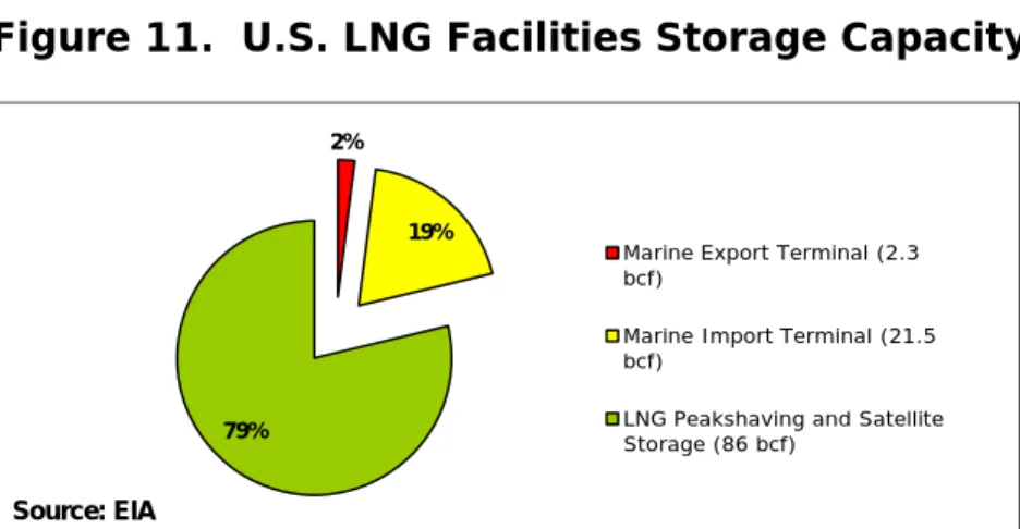
There are about 260 LNG facilities worldwide. The U.S. has the largest number of those with about 121 active facilities. Natural gas is liquefied and stored at about 58 facilities in 25 states, including 96 connected to the U.S. natural gas pipeline grid. Massachusetts alone accounts for 14 major satellite facilities, or roughly 40 percent of all satellite facilities in the United States. New Jersey has five satellite LNG facilities, the second highest in the U.S. A rough summary of the types of LNG storage capacity in the U.S. is shown in Figure 11. According to the U.S. Energy Information Administration (EIA),16 the estimated total storage capacity of LNG peak shaving and satellite facilities in the Lower 48 States as of mid-2004 is 86 billion cubic feet (BCF). LNG peak shaving and satellite storage account for 79 percent of U.S. LNG storage capacity, but it is only two percent of the total natural gas storage capability in the Lower 48. For example, in addition to LNG peak shaving and storage, domestic natural gas production is stored in underground caverns or depleted natural gas fields, which together account for the overwhelming proportion of natural gas storage capacity.
Figure 11. U.S. LNG Facilities Storage Capacity
2%
19%
79%
Marine Export Terminal (2.3 bcf)
Marine Import Terminal (21.5 bcf)
LNG Peakshaving and Satellite Storage (86 bcf)
Source: EIA
Despite the relatively low percentage of total gas storage capacity represented, the high daily deliverability of LNG facilities makes them an important source of fuel during winter cold snaps. LNG facilities can deliver up to about 11 BCFD (BCF per day), or the equivalent of 14 percent of the quantity of gas supply that can be delivered from underground storage locations in the U.S.
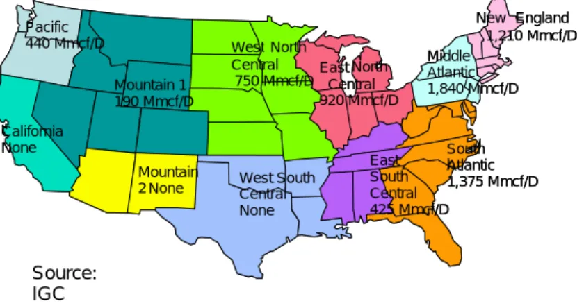
Figure 12. U.S. Regional LNG Storage Deliverability
Application of Safety Conditions to the LNG Value Chain
In this paper, we do not address risks and hazards associated with exploration and production activities, processing of natural gas or safety and security associated with natural gas pipeline or local gas utility distribution systems. The U.S. and other countries maintain health, safety, and environment (HSE) policies and regulations that apply to all of these activities and sites as well as specialized policies, regulations, and industry standards targeted to specific needs and hazards. Worldwide, best practices for all of these activities have evolved and are becoming more firmly embedded in contractual and regulatory frameworks that establish the safety conditions of industry operations. The specific safety and security features embedded in the LNG value chain, as they pertain to the four elements of primary containment, secondary containment, safeguard systems and separation distances, are detailed below, following our schematic in Figure 2 of the multiple layers of protection.
PRIMARY CONTAINMENT
International standards and rules define containment with respect to types of structures and technologies in use. We use the term “containment” in this document to mean safe storage and isolation of LNG. Safe use of LNG, or any cryogenic substance, requires an understanding of how materials behave at cryogenic temperatures. For example, at extremely low temperatures, carbon steel loses its ductility and becomes brittle. The material selected for tanks, piping, and
New England 1,210 Mmcf/D Middle Atlantic 1,840 Mmcf/D South h Atlantic 1,375 Mmcf/D East South Central 425 Mmcf/D East North Central 920 Mmcf/D West South Central None West North Central 750 Mmcf/D Pacific 440 Mmcf/D California None Mountain 1 190 Mmcf/D Mountain 2 None Source: IGC New England 1,210 Mmcf/D Middle Atlantic 1,840 Mmcf/D South h Atlantic 1,375 Mmcf/D East South Central 425 Mmcf/D East North Central 920 Mmcf/D West South Central None West North Central 750 Mmcf/D Pacific 440 Mmcf/D California None Mountain 1 190 Mmcf/D Mountain 2 None
other equipment that comes in contact with LNG is critical. The use of high nickel content steels, aluminum, and stainless steels is costly but necessary to prevent embrittlement and material failures. High alloy steels composed of nine percent nickel and stainless steel typically are used for the inner tank of LNG storage tanks and for other LNG applications.
Several engineering design features ensure the safety of LNG storage tanks (see Figure 13 below). LNG typically is stored in double-walled tanks at atmospheric pressure. The storage tank is a tank within a tank, with insulation between the walls of the tanks.
Figure 13. Conceptual Design of Storage Tanks
In single containment tanks, the outer tank is generally made of carbon steel. It provides no protection in the event of the failure of the inner tank, but holds the insulation in place. The inner tank, in contact with the LNG liquid, is made of materials suitable for cryogenic service. It has a flat metallic bottom and a cylindrical metal wall both built of materials suitable for cryogenic temperatures (usually nine percent nickel steel). Pre-stressed concrete and aluminum have also been used for inner tanks. The inner tank bottom rests on a rigid insulation
Source: Shell
(where required by code)
material, such as foam glass. The strength of the total tank must withstand the hydrostatic load of the LNG. This hydrostatic head determines the thickness of the inner tank side walls. The tanks also have an insulation layer with a flat suspended deck supported by an outside domed roof vapor barrier or outer tank (often made of carbon steel). All new tank piping designs are through the roof of the tank to avoid siphoning of the full content of the tank in case of piping failures.
A single containment tank (shown in Figure 14 below) for LNG is a tank system comprised of an inner tank and an outer container. The engineering design requires only the inner tank to meet the low temperature ductility requirements for storage of the product. The outer container of a single containment storage tank serves primarily to retain insulation and vapor. It is not designed to contain LNG due to leakage from the inner tank. Storage tanks may also use double or full containment designs as described in the following section on Secondary Containment. In double or full containment, the outer tank is designed to contain the full amount of the inner tank in case of a failure of the inner tank.
Figure 14. Single Containment Tanks
Engineering design for safety also applies to LNG ships. An onboard containment system stores the LNG, where it is kept at atmospheric pressure (to keep air from entering the tank) and at -256oF (-160oC). Existing LNG ship cargo containment systems reflect one of three designs. As of October 2011:
Spherical (Moss) design accounts for 30 percent of the existing ships,
Membrane design account for about 68 percent, and
Self-supporting structural prismatic design account for about 2 percent. Source: Williams
Ships with spherical tanks are most readily identifiable as LNG ships because the
tank covers are visible above the deck (see Figure 15).
Figure 15. A Spherical Tank
Many ships currently under construction, however, are membrane type ships. The
membrane and prismatic ships look more like oil tankers with a less visible
containment tank structure above the main deck. The cargo containment systems of membrane-type LNG ships (see Figure 16) are made up of a primary container, a secondary containment, and further insulation.
Figure 16. LNG Lagos - Membrane Type LNG Carrier
The primary container is the primary containment for the cargo. It can be constructed of stainless steel, invar (36 percent nickel steel). The most common
Source: NLNG
cargo insulation materials include polyurethane, polyvinyl chloride foam, polystyrene, and perlite. Nitrogen is placed in the insulation space. Because nitrogen does not react with other gases or materials, even minor leaks can be detected by monitoring the nitrogen-filled insulation space for the presence of methane.
SECONDARY CONTAINMENT
Secondary containment provides protection beyond the primary containment. This applies both to storage tanks at receiving/re-gasification terminals as well as LNG ships. A dike, berm, or dam impoundment usually surrounds a single containment tank located onshore in order to contain any leakage in the unlikely event of tank failure. This system allows any released LNG to be isolated and controlled. The dikes are designed to contain 100 percent to 110 percent of tank volume and to be high enough so that the trajectory of a leak at the upper liquid level in the tank will not overshoot the edge of the dike. Most of the existing LNG tanks at U.S. peak shaving facilities and marine import facilities are single containment with secondary containment provided via impoundments. Single containment tanks require larger land areas for LNG storage facilities because of the larger potential spill area of the dike impoundment.
A double containment tank (illustrated in Figure 17) is designed and constructed so that both the inner tank and the outer tank are capable of independently containing the refrigerated liquid. The inner tank contains the LNG under normal operating conditions. The outer tank or wall is intended to contain any LNG leakage from the inner tank and the boil-off gas. The majority of LNG storage tanks built recently around the world is designed as double or full containment tanks.
Figure 17. Double Containment Tanks
Similar to a double containment tank, a full containment tank is designed and constructed so that both the inner tank and the outer tank are capable of independently containing the stored LNG. The inner tank contains the LNG under standard operating conditions. The outer tank or wall composed of approximately three feet of concrete is one to two meters away from the inner tank. The outer tank supports the outer roof and is intended to contain the LNG.17 The tanks are designed in accordance with international LNG codes (EMMUA 147,18 EN 1473). The full containment tank is less susceptible to damage from external forces. Full containment LNG tanks, with reinforced concrete walls and roofs can be found in Japan, Korea, Greece, Turkey, Portugal (see Figure 18). Cameron LNG, LLC has recently built a full containment LNG tank system for the new LNG terminal in Hackberry, Louisiana.
17 All protocols on tank design and safety based on British Standards Institution (BSI) BS 7777: 1993 Parts 1. See http://www.hse.gov.uk/comah/sragtech/docsbsi.htm.
18 U.K. Engineering Equipment and Materials Users Association (EEMUA), 1986,
http://www.hse.gov.uk/comah/sragtech/techmeasplant.htm.
Figure 18. Full Containment Tanks
The safety records of the onshore LNG facilities around the world demonstrate that the primary containment of the LNG tanks is safe, because secondary spill
containment systems installed around all of the tanks, have never been required to
hold liquid. LNG operators also are required to provide containment and design of troughs to direct the flow of LNG to a drain sump in a safe location in those process areas where an LNG spill could occur, such as in transfer piping or LNG truck loading areas and vaporization units.
For LNG ships, regulations concerning a secondary barrier depend on the type of construction of the storage tanks. It may be a complete secondary containment mechanism for membrane design ships that is equivalent to the primary barrier. In the case of ships with independent tanks, such as the spherical and structural prismatic design systems, the secondary barrier is a splash barrier with a drip pan at the bottom from which accumulated liquid evaporates (see Figure 19). Materials used to construct the secondary barrier include aluminum or stainless steel foil, stainless steel and invar.
Figure 19. Tank Section of a Spherical Moss Design
SAFEGUARD SYSTEMS
All LNG facilities are designed to comply with spill containment requirements. They have extensive safety systems to detect LNG releases using a number of gas detectors (for methane), ultraviolet or infrared fire detectors, smoke or combustion product detectors, low temperature detectors and detectors to monitor LNG levels and vapor pressures. Closed-circuit television systems monitor all critical locations of LNG facilities. Emergency shutdown systems can be activated upon detection of leaks, spills, or gas vapors. While there are different types of designs for LNG facilities HSE considerations are generally similar. Various codes and standards (see later section on Industry Standards/Regulatory Compliance) ensure that the chances of a release are minimal, as is its volume if a release occurs.
LNG transfer lines are designed to prevent releases. Should there be a failure of a
segment of piping at an LNG facility, a spill of LNG or leak of gas vapor could occur. An LNG spill from a transfer line is very unlikely due to the design requirements for equipment, such as use of proper materials of construction, minimal use of bolted flanges and rigorous testing of LNG piping. Gas and fire detectors throughout the facility activate alarms and foam systems to ensure rapid dispersion or containment of gas vapors and any fire hazard.
Fire detection sensors at LNG facilities would sound an alarm and immediately
immediately from automated firefighting systems. If there is an ignition source, then a pool fire would develop at the liquid LNG release point. LNG vapor burns with very little smoke. The LNG quickly evaporates due to the heat of the surroundings and the flame. If a release of LNG goes unignited for a period of time, then a vapor cloud can form. If ignited, a vapor cloud burns back to the source of the release. The speed of burn depends on conditions such as the size of the release and weather conditions.
LNG ships are designed with a double hull. This design provides optimum protection for the integrity of the cargo in the event of collision or grounding as well as separate ballast. Separate from the hull design, LNG ships have safety
equipment to facilitate ship handling and cargo system handling. The ship-handling
safety features include sophisticated radar and positioning systems that enable the crew to monitor the ship’s position, traffic and identified hazards around the ship. A global maritime distress system automatically transmits signals if there is an onboard emergency requiring external assistance. The cargo-system safety features include an extensive instrumentation package that safely shuts down the system if it starts to operate outside of predetermined parameters. Ships also have gas and fire detection systems, and nitrogen purging. Should fire occur on a ship, two 100 percent safety relief valves are designed to release the ensuing boil off to the atmosphere without over-pressurizing the tank.
LNG ships use approach velocity meters when berthing to ensure that the prescribed impact velocity for the berth fenders are not exceeded. When moored, automatic mooring line monitoring provides individual line loads to help maintain the security of the mooring arrangement while alongside. When connected to the onshore system, the instrument systems and the shore-ship LNG transfer system acts as one system, allowing emergency shutdowns of the entire system from ship and from shore.
LNG ships and facilities have redundant safety systems, for example, Emergency Shutdown systems (ESD). A redundant safety system shuts down unloading operations when the ship or unloading facility is not performing within the design parameters.
SEPARATION DISTANCE
In the U.S., regulators regulate setbacks or protection distances for LNG storage and other facilities. The federal safety standards on LNG facilities are found in the U.S. Code of Federal Regulations (CFR) 49, Part 193.19 Setbacks are important for protecting surrounding areas should the unlikely release of LNG or a fire occur at an LNG facility. The regulations specify that each LNG container and LNG transfer systems have a thermal radiation protection zone beyond the impoundment area.20 Each onshore LNG container or tank must be within a secondary dike or impoundment area. These thermal radiation exclusion zones must be large enough so that the heat from an LNG fire does not exceed a specified limit for people and property. The thermal radiation exclusion zone must be owned or controlled by the operator of the LNG facility. The code also specifies how the thermal radiation distance is calculated for each LNG facility. The Gas Technology Institute (GTI) computer model or a similar model is to be used and wind speed, ambient temperature and relative humidity producing the maximum exclusion distances are to be applied subject to other detailed provision of the regulation.
Similar to the provision for thermal radiation protection, the U.S. federal regulation 49 CFR Part 193 specifies that each LNG container and LNG transfer system must have a flammable vapor dispersion exclusion zone around the facility that is owned or controlled by the facility operator. The vapor dispersion exclusion zone must be large enough to encompass that part of the vapor cloud which could be flammable. The code specifies how the flammable vapor dispersion distance is calculated for each LNG facility. In order to account for irregular mixing of the vapor cloud, the regulation designates the vapor cloud hazard area as the area where the average gas concentration in air is equal to or greater than 2.5 percent (half of the lower flammability limit of methane). This provides a margin of safety to account for irregular mixing. The regulation also specifies other parameters including
19 49 CFR Part 193:
http://ecfr.gpoaccess.gov/cgi/t/text/text-idx?c=ecfr&rgn=div5&view=text&node=49:3.1.1.1.9&idno=49.
20 The term impoundment is used in the LNG industry to identify a spill control design that will direct and contain the liquid in case of a release. Earthen or concrete dikes may provide impoundment surrounding an LNG container.
dispersion conditions that should be used in computing the dispersion distances. Computer models are used to calculate dispersion distances. Under U.S. regulations, protection distances are to be calculated specific to each location to prevent exposure to fire or thermal radiation.
Safety zones differ for ships in transit as opposed to ships in port. Port safety
zones are established by the USCG and port captain, based on the specific risk factors at a given terminal. There are two purposes for safety zones for LNG ships – to minimize collision while the ship is underway, and at berth to protect surrounding property and personnel from hazards that could be associated with ignition. In the U.S., the use of safety zones around LNG ships began in 1971 at the Everett Terminal in Boston Harbor. Safety zones are established based on the specific circumstances, including navigational requirements, in a specific area.
In some ports, the USCG may require a tug escort and specified safety zones around LNG ships when a ship is underway to a U.S. receiving terminal. The USCG’s intention is to minimize disruption to area shipping and boating traffic while ensuring safe operations. Tugs assist in the safe docking of LNG ships. Figure 20 shows an example of a safety zone around the LNG tanker at Cove Point LNG terminal.