What is the difference
between an equivalent time
sampling oscilloscope and a
real-time oscilloscope?
Application Note
In the past, deciding between an equivalent time sampling oscilloscope and a real time oscilloscope was a matter of determining your bandwidth requirements; but with today’s high performance instruments that distinction isn’t as clear. This document will discuss how each type of scope samples the incoming waveform and explain the trigger requirements. A summary detailing the advantages of each scope is provided at the end.
Real-time oscilloscope
A real-time oscilloscope, sometimes called a “single-shot” scope, captures an entire waveform on each trigger event. Put another way, this means that a large number of data points are captured in one continuous record. To better understand this type of data acquisition, imagine it as an extremely fast analog-to-digital converter (ADC) in which the sample rate determines the sample spacing and the memory depth determines the number of points that will be displayed. In order to capture any waveform, the ADC sampling rate needs to be significantly faster than the frequency of the incoming waveform. This sample rate, which can be as fast as 80 GSa/s, determines the bandwidth which currently extends
to 63 GHz.
The real-time scope can be triggered on a feature of the data itself, and often a trigger will occur when the incoming waveform’s amplitude reaches a certain threshold. It is at this point that the scope starts converting the analog waveform to digital data points at a rate asynchronous and very much unrelated to the input waveform’s data rate. That conversion rate, known as the sampling rate, is typically derived from an internal clock signal. The scope samples the amplitude of the input waveform, stores that value in memory, and continues to the next sample as illustrated in Figure 1. The trigger’s main job is to provide a horizontal time reference point for the incoming data.
Input signal
Sample clock
Trigger signal
Reconstructed waveform
t
st
dTriggering the real-time
oscilloscope
Real-time oscilloscope
as an ADC
Equivalent time sampling oscilloscope
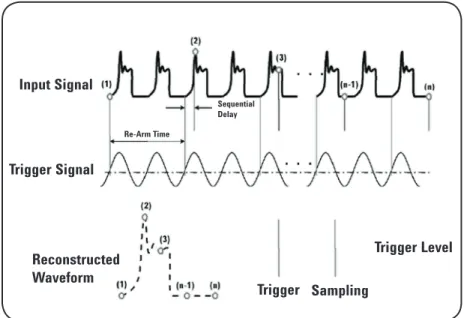
An equivalent time sampling oscilloscope, sometimes simply called a “sampling scope,” measures only the instantaneous amplitude of the waveform at the sampling instant. In contrast to the real-time scope, the input signal is only sampled once per trigger. The next time the scope is triggered, a small delay is added and another sample is taken. The intended number of samples determines the resulting number of cycles needed to reproduce the waveform. The
measurement bandwidth is determined by the frequency response of the sampler which currently can extend beyond 80 GHz.
The triggering and subsequent sampling of an equivalent time sampling oscilloscope is different from a real-time oscilloscope in some very tangible ways. Most importantly, the equivalent time sampling scope needs an explicit trigger in order to operate, and this trigger needs to be synchronous with the input data. Typically this trigger is provided by the user but, in some cases, the trigger can be obtained using a hardware clock recovery module. The sampling works as follows: A trigger event initiates the acquisition of the first sample, then the scope rearms and waits for another trigger event. The rearm time is approximately 25 μs. The next trigger event initiates the second acquisition and adds a precise incremental delay before sampling the second data point. This incremental delay time is determined by the time base setting and the number of sample points. This process, which is illustrated in Figure 2, is repeated until the entire waveform is acquired.
Input Signal
Sequential Delay Re-Arm Time
Trigger Sampling
Trigger Level
Re-Arm Time
Trigger Signal
Reconstructed Waveform
Figure 2 - Waveform acquisition using an equivalent time sampling oscilloscope
One sample per cycle
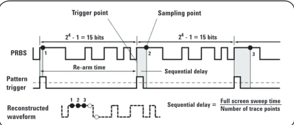
There are two ways to trigger an equivalent time sampling oscilloscope and each results in a different data viewing format; either a bit stream or an eye diagram. Viewing the individual bits in the signal allows the user to see the pattern dependencies in the system, but does not allow for high resolution with large numbers of bits. In order to view a bit stream, the trigger must only pulse once during the period of the input pattern and must be at the same relative location in the bit pattern for each event. The input signal is then sampled and upon the next trigger event, the incremental delay is added and the bit steam is sampled until the entire waveform is acquired. In order to view a bit stream on an equivalent time scope, you must have a repetitive waveform; otherwise a real-time scope is needed. The triggering process to display a bit stream waveform is shown in Figure 3.
Triggering the equivalent
time sampling scope
PRBS Pattern trigger Reconstructed waveform
Sequential delay = Full screen sweep timeNumber of trace points
Trigger point Sampling point
24 - 1 = 15 bits 24 - 1 = 15 bits
Re-arm time Sequential delay
Figure 3 - Sampling Process for a Bit Steam Pattern Waveform
Eye diagram
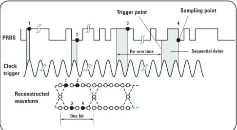
The other viewing mode is the eye diagram. This mode does not require a repetitive waveform and can help to determine noise, jitter, distortion, and signal strength among many other measurements. It gives an overall statistical view of the system’s performance as it looks at an overlay of every combination of bits in the bit steam. The triggering required for this mode is a synchronous clock signal. At each trigger event, allowing for rearm time, the scope samples the data and builds the combination of all possible 1 and 0 combinations across the screen. Full rate clocks as well as divided rate clocks can be used for the trigger, however if the length of the pattern is an even multiple of the clock divide ratio, the eye diagram will be missing combinations and will therefore be incomplete. In addition, if the data is used as its own trigger, the eye diagram may appear complete, but the scope is only triggered on rising edges of the data pattern. This should be avoided to make accurate eye diagram measurements. The triggering process to display an eye diagram is shown in Figure 4.
It is important to note that an eye diagram may also be viewed with newer real-time oscilloscopes. These “real-real-time eyes” or “single-shot” eye diagrams are constructed using a software recovered clock or an external explicit clock provided by the user. The real-time scope slices the single long capture waveform at times equal to the recovered clock cycle and overlays these bits to recreate the eye diagram.
Trigger point Sampling point
One bit
Re-arm time Sequential delay
PRBS
Clock trigger
Reconstructed waveform
Figure 4 - Sampling Process for an Eye Diagram Waveform
Creating an eye diagram
• Able to display one-time transient events
• No explicit trigger needed • Does not require a repetitive
waveform
• Measures cycle to cycle jitter directly
• Large record lengths/ deep memory • Great for troubleshooting
• Lower sampling rate allows higher resolution ADC conversion • Wider bandwidth
• Lower noise floor • Lower intrinsic jitter
• Can include front end optical modules
• Can achieve solutions at a reduced cost
Advantages of equivalent time sampling scopes
Advantages of real-time scopes
Publication title Publication type Publication number
Infiniium 90000 Q-Series Oscilloscopes Data sheet 5989-9712EN
N2807A PrecisionProbe Advanced Kit Data sheet 5991-0263EN
86100D Wide-Bandwidth Oscilloscope Data sheet 5990-5824EN
E2688A, N5384A High-Speed Serial Data Analysis and Data sheet 5989-0108EN
Clock Recovery Software
EZJIT Plus Jitter Analysis Software Data sheet 5989-0109EN
Related literature
Agilent Technologies Oscilloscopes
myAgilent
myAgilent
www.agilent.com/find/myagilent
A personalized view into the information most relevant to you.
www.axiestandard.org
AdvancedTCA® Extensions for Instrumentation and Test (AXIe)
is an open standard that extends the AdvancedTCA for general purpose and semiconductor test. Agilent is a founding member of the AXIe consortium.
www.lxistandard.org
LAN eXtensions for Instruments puts the power of Ethernet and the Web inside your test systems. Agilent is a founding member of the LXI consortium.
www.pxisa.org
PCI eXtensions for Instrumentation (PXI) modular instrumentation delivers a rugged, PC-based high-performance measurement and automation system.
Three-Year Warranty
www.agilent.com/find/ThreeYearWarranty
Agilent’s combination of product reliability and three-year warranty coverage is another way we help you achieve your business goals: increased confidence in uptime, reduced cost of ownership and greater convenience.
Agilent Advantage Services
www.agilent.com/find/AdvantageServices
Accurate measurements throughout the life of your instruments.
www.agilent.com/quality
Agilent Electronic Measurement Group DEKRA Certified ISO 9001:2008 Quality Management System
Agilent Channel Partners
www.agilent.com/find/channelpartners
Get the best of both worlds: Agilent’s measurement expertise and product breadth, combined with channel partner convenience.
www.agilent.com
For more information on Agilent Technologies’ products, applications or services, please contact your local Agilent office. The complete list is available at:
www.agilent.com/find/contactus Americas
Canada (877) 894 4414 Brazil (11) 4197 3600 Mexico 01800 5064 800 United States (800) 829 4444
Asia Pacific
Australia 1 800 629 485
China 800 810 0189
Hong Kong 800 938 693 India 1 800 112 929 Japan 0120 (421) 345
Korea 080 769 0800
Malaysia 1 800 888 848 Singapore 1 800 375 8100 Taiwan 0800 047 866 Other AP Countries (65) 375 8100
Europe & Middle East
Belgium 32 (0) 2 404 93 40 Denmark 45 45 80 12 15 Finland 358 (0) 10 855 2100 France 0825 010 700*
*0.125 €/minute Germany 49 (0) 7031 464 6333 Ireland 1890 924 204 Israel 972-3-9288-504/544 Italy 39 02 92 60 8484 Netherlands 31 (0) 20 547 2111 Spain 34 (91) 631 3300 Sweden 0200-88 22 55 United Kingdom 44 (0) 118 927 6201
For other unlisted countries: www.agilent.com/find/contactus
(BP-09-27-13)
Product specifications and descriptions in this document subject to change without notice.
© Agilent Technologies, Inc. 2013 Published in USA, November 18, 2013 5989-8794EN