Smart Array 431 Controller
User GuideFirst Edition (September 1999) Part Number 146915-001 Compaq Computer Corporation
COMPAQ COMPUTER CORPORATION SHALL NOT BE LIABLE FOR TECHNICAL OR EDITORIAL ERRORS OR OMISSIONS CONTAINED HEREIN, NOR FOR INCIDENTAL OR CONSEQUENTIAL DAMAGES RESULTING FROM THE FURNISHING, PERFORMANCE, OR USE OF THIS MATERIAL. THIS INFORMATION IS PROVIDED “AS IS” AND COMPAQ COMPUTER CORPORATION DISCLAIMS ANY WARRANTIES, EXPRESS, IMPLIED OR STATUTORY AND EXPRESSLY DISCLAIMS THE IMPLIED WARRANTIES OF
MERCHANTABILITY, FITNESS FOR PARTICULAR PURPOSE, GOOD TITLE AND AGAINST INFRINGEMENT.
This publication contains information protected by copyright. No part of this publication may be photocopied or reproduced in any form without prior written consent from Compaq Computer Corporation.
© 1999 Compaq Computer Corporation. All rights reserved. Printed in the U.S.A.
The software described in this guide is furnished under a license agreement or nondisclosure agreement. The software may be used or copied only in accordance with the terms of the agreement.
Compaq, Deskpro, Fastart, Compaq Insight Manager, Systempro, Systempro/LT, ProLiant, ROMPaq, QVision, SmartStart, NetFlex, QuickFind, PaqFax, ProSignia, registered United States Patent and Trademark Office.
Active Answers, Netelligent, Systempro/XL, SoftPaq, QuickBlank, QuickLock are trademarks and/or service marks of Compaq Computer Corporation.
Microsoft, Windows and Windows NT are registered trademarks of Microsoft Corporation Intel, Pentium and Xeon are trademarks and/or registered trademarks of Intel Corporation. Other product names mentioned herein may be trademarks and/or registered trademarks of their respective companies.
Compaq Smart Array 431 Controller User Guide First Edition (September 1999)
Contents
About This Guide
Text Conventions...ix
Symbols in Text...x
Symbols on Equipment...xi
Getting Help ...xi
Compaq Technical Support ...xii
Compaq Website...xii
Compaq Authorized Reseller...xii
Chapter 1
Features
Overview of Features... 1-1 Smart Array 431 Controller ... 1-2 Drive Arrays ... 1-3 Fault Tolerance ... 1-4 Drive Movement... 1-4 Read-Cache Memory ... 1-4 Expanding and Extending Capacity... 1-4 Online RAID Level and Stripe Size Migration... 1-5 SCSI Support ... 1-5 Array Configuration Utilities... 1-6 Options Rom Configuration for Arrays (ORCA) ... 1-6 Array Configuration Utility (ACU) ... 1-6
Chapter 2
Installation Preparation
Option Kit Contents ... 2-2 SmartStart and Support Software CD ... 2-2 Controller Products Documentation CDs... 2-2 Hardware and Software Installation Guidelines... 2-3 Guidelines for Making Changes to Current Installation... 2-4 Installing Multiple Smart Array 431 Controllers ... 2-4 Drive Considerations ... 2-4 Determining Maximum Storage Capacity ... 2-5 Expanding the Capacity of an Array... 2-5 Changing the Fault Tolerance ... 2-6 Moving Drives Offline... 2-6
Chapter 3
Updating the Firmware
ROMPaq Diskettes... 3-2 Materials Needed ... 3-2 Creating Diskettes... 3-2 Running System ROMPaq ... 3-3 Running Options ROMPaq ... 3-4
Chapter 4
Controller Installation and Cabling Information
Tools Needed ... 4-1 Preparing the Server... 4-2 Installing the Smart Array 431 Controller... 4-2 SCSI Port Utilization ... 4-3 SCSI Termination ... 4-3 SCSI IDs ... 4-4 Internal Cabling for Compaq Servers... 4-4 Internal Drives and Cabling ... 4-4 External Cabling for Compaq Servers ... 4-5 External SCSI Connections... 4-6 External Cables ... 4-6 External Cabling Instructions... 4-8 Completing the Installation... 4-9
About This Guide v
Chapter 5
Running the System Configuration Utility
System Configuration Utility on CD ... 5-2 System Configuration Diskettes ... 5-2 Starting the System Configuration Utility ... 5-3 Configuring the Controller... 5-4
Chapter 6
Array Configuration Utilities
Selecting the Correct Utility ... 6-1 Option Rom Configuration for Arrays (ORCA)... 6-1 Array Configuration Utility (ACU) ... 6-2 Option Rom Configuration for Arrays... 6-2 Functionality... 6-2 Restrictions ... 6-2 Starting the Option Rom Configuration for Arrays Utility... 6-3 Creating a Logical Drive ... 6-3 Deleting a Logical Drive ... 6-4 Confirmation Screen... 6-4 Array Configuration Utility ... 6-4 Before You Begin... 6-5 Starting the Array Configuration Utility... 6-6 Configuration Wizards ... 6-7 Online Help ... 6-7 Configuration Procedures ... 6-8 Array Configuration Utility Screens... 6-22 NetWare Online Array Configuration Utility (CPQONLIN) ... 6-30
Chapter 7
Installing the Operating System Drivers
Materials Needed ... 7-2 Novell NetWare ... 7-2 Creating Novell SSD Diskettes ... 7-2 Additional Information ... 7-3 Installation Procedure ... 7-3 Compaq Online Array Configuration Utility for NetWare (CPQONLIN) ... 7-4 Optimizing Array Controller Performance ... 7-4 Microsoft Windows NT 4.0 ... 7-5 Materials Needed... 7-5 Creating the Windows NT SSD Diskettes ... 7-5 Additional Information ... 7-6 Installation Procedures ... 7-7
Installing the Operating System Drivers
continued
SCO OpenServer 5... 7-10 Getting the Driver and Installation Information... 7-10 Creating the EFS Diskettes ... 7-10 Accessing the Information ... 7-11 SCO UnixWare 2.1 or Later ... 7-12 Getting the Driver and Installation Information... 7-12 Creating the EFS Diskettes ... 7-12 Accessing the Information ... 7-13 IBM OS/2... 7-14 Installing the Driver ... 7-14 Creating a Support Software Diskette (SSD)... 7-14 Additional Information ... 7-15 Installation Procedures... 7-15 Controller Ordering... 7-16 Partitioning ... 7-17 Booting OS/2 from a Smart Array 431 Controller Drive... 7-17 Command Line Switches ... 7-18 Limitations ... 7-20 Updating the Compaq Insight Manager Agents ... 7-20
Appendix A
Regulatory Compliance Notices
Federal Communications Commission Notice... A-1 Class A Equipment... A-2 Class B Equipment... A-2 Modifications ... A-3 Cables ... A-3 Canadian Notice (Avis Canadien)... A-3 Class A Equipment ... A-3 Class B Equipment... A-4 European Union Notice... A-4 Japanese Notice... A-4
About This Guide vii
Appendix B
Electrostatic Discharge
Preventing Electrostatic Damage...B-1 Grounding Methods ...B-2
Appendix C
Specifications
Appendix D
Understanding Drive Arrays
What is a Drive Array? ...D-1 Drive Arrays ...D-4 Logical Drives ...D-4 Drive Array Benefits...D-5 Data Protection ...D-5 Performance Enhancement ...D-10 Distributing Data and Data Striping ...D-10 Concurrent I/O Request Servicing...D-11 Optimized Request Management...D-11 Bus Master Data Transfers ...D-12 Adding Storage Capacity ...D-12 Online Capacity Expansion or Extension ...D-15 Disk Drive Capacity Upgrades ...D-15 Data Reliability...D-16 Auto Reliability Monitoring ...D-16 Dynamic Sector Repairing...D-16 Drive Parameter Tracking...D-17 Drive Failure Alert Features ...D-17 Interim Data Recovery...D-17 Automatic Data Recovery...D-18 Hot-Pluggable Drives ...D-18 Controller Duplexing ...D-21 Software-Based Drive Mirroring ...D-21
Appendix E
Appendix F
Recovering from Drive Failure
Recognizing a Drive Failure ... F-1 Fault Tolerance and Drive Failure ... F-2 A Non-Fault-Tolerant (RAID 0) Logical Drive... F-2 A RAID 1 (Mirroring) Logical Drive ... F-2 A RAID 5 (Distributed Data Guarding) Logical Drive... F-3 Spare Drives... F-3 Replacing a Failed Drive... F-4 Automatic Data Recovery... F-4 Automatic Data Recovery Failure... F-5 Compromised Fault Tolerance ... F-5
Appendix G
POST Error Messages
Appendix H
Questions and Answers
About This Guide
This guide is designed to be used as step-by-step instructions for installation and as a reference for operation, troubleshooting, and future upgrades.
WARNING: To reduce the risk of personal injury from electrical shock and hazardous energy levels, only authorized service technicians should attempt to install this equipment. Consult the Safety Information and User documentation provided with your computer before attempting this installation.
Many servers and workstations are cabable of producing energy levels that are considered hazardous and are only intended to be serviced by qualified personnel trained in dealing with these hazards. Do not remove enclosures or attempt to bypass any interlocks that may be provided for the purpose of removing these harardous conditions.
Text Conventions
This document uses the following conventions to distinguish elements of text: Keys Keys appear in boldface. A plus sign (+) between
two keys indicates that they should be pressed simultaneously.
USER INPUT User input appears in a different typeface and in uppercase.
Menu Options, Command Names, Dialog Box Names
These elements appear in initial capital letters.
COMMANDS,
DIRECTORY NAMES, and DRIVE NAMES
These elements appear in uppercase.
Type When you are instructed to type information, type the information without pressing the Enter key. Enter When you are instructed to enter information, type
the information and then press the Enter key.
Symbols in Text
These symbols may be found in the text of this guide. They have the following meanings.
WARNING: Text set off in this manner indicates that failure to follow directions in the warning could result in bodily harm or loss of life.
CAUTION: Text set off in this manner indicates that failure to follow directions could result in damage to equipment or loss of information.
IMPORTANT: Text set off in this manner presents clarifying information or specific instructions.
NOTE: Text set off in this manner presents commentary, sidelights, or interesting points of information.
About This Guide xi
Symbols on Equipment
These icons may be located on equipment in areas where hazardous conditions may exist.
Any surface or area of the equipment marked with these symbols indicates the presence of electrical shock hazards. Enclosed area contains no operator serviceable parts.
WARNING: To reduce the risk of injury from electrical shock hazards, do not open this enclosure.
Any RJ-45 receptacle marked with these symbols indicates a Network Interface Connection.
WARNING: To reduce the risk of electrical shock, fire, or damage to the equipment, do not plug telephone or telecommunications connectors into this receptacle.
Any surface or area of the equipment marked with these symbols indicates the presence of a hot surface or hot component. If this surface is contacted, the potential for injury exists.
WARNING: To reduce the risk of injury from a hot component, allow the surface to cool before touching.
Power Supplies or Systems marked with these symbols indicate the equipment is supplied by multiple sources of power.
WARNING: To reduce the risk of injury from electrical shock, remove all power cords to completely disconnect power from the system.
Getting Help
If you have a problem and have exhausted the information in this guide, you can get further information and other help in the following locations.
Compaq Technical Support
You are entitled to free hardware technical telephone support for your product for as long you own the product. A technical support specialist will help you diagnose the problem or guide you to the next step in the warranty process. In North America, call the Compaq Technical Phone Support Center at 1-800-OK-COMPAQ1. This service is available 24 hours a day, 7 days a week. Outside North America, call the nearest Compaq Technical Support Phone Center. Telephone numbers for world wide Technical Support Centers are listed on the Compaq website. Access the Compaq website by logging on to the Internet at http://www.compaq.com.
Be sure to have the following information available before you call Compaq:
■ Technical support registration number (if applicable)
■ Product serial number(s)
■ Product model name(s) and numbers(s)
■ Applicable error messages
■ Add-on boards or hardware
■ Third-party hardware or software
■ Operating system type and revision level
■ Detailed, specific questions
Compaq Website
The Compaq website has information on this product as well as the latest drivers and Flash ROM images. You can access the Compaq website by logging on to the Internet at http://www.compaq.com.
Compaq Authorized Reseller
For the name of your nearest Compaq Authorized Reseller:
■ In the United States, call 1-800-345-1518.
■ In Canada, call 1-800-263-5868.
■ Elsewhere, see the Compaq website for locations and telephone number
1
Chapter
1
Features
The Compaq Smart Array 431 Controller is a single-channel, 64-bit PCI array controller that is part of the Compaq Smart Array family of controllers. It supports Wide Ultra3 SCSI technology for faster data transfer rates
(160-MB/s, and is backward compatible with the Wide Ultra2 and Wide-Ultra SCSI-devices.) The Smart Array 431 Controller supports one SCSI channel that can be accessed through either the external VHDCI connector or the internal 68-pin Wide SCSI connector.
Overview of Features
Features of the Smart Array 431 Controller option board includes:
■ Supports RAID 0, 1, 0+1 (also called RAID 10), and RAID 5
■ Supports Wide Ultra3 SCSI technology, with a transfer rate up to (160-MB/s)
■ Supports Wide Ultra3 SCSI, Wide Ultra2 SCSI and Wide-Ultra SCSI-3 hard drives
■ Single Wide Ultra3 SCSI channel supporting up to 15 drives
■ Internal 68-pin Wide SCSI connector and external VHDCI connector
■ Performance monitoring through full Compaq Insight Manager support
■ Automatic and manual performance tuning
■ Pre-failure notification and warranty for Compaq disk drives
■ Tagged command queuing
■ 64-bit PCI Bus Master interface
■ 16-MB of d-RAM used for code data and non-battery backed read cache
■ Forward upgradability to the Compaq Smart Array 3200 or 4200 Controller
■ Support for offline drive and array movement
■ Online capacity expansion
■ Logical drive extension
■ RAID level migration
■ Stripe-size migration
■ Easy-to-use Array Configuration Utilities
NOTE: If higher performance, higher availability, or higher capacity is required, arrays can be moved from the Smart Array 431 Controller to a Smart Array 3200 or 4200 Controller without requiring a backup and restore. These controllers provide higher performance, multiple SCSI channels, greater amounts of read/write cache (battery backed and removable).
Features 1-3
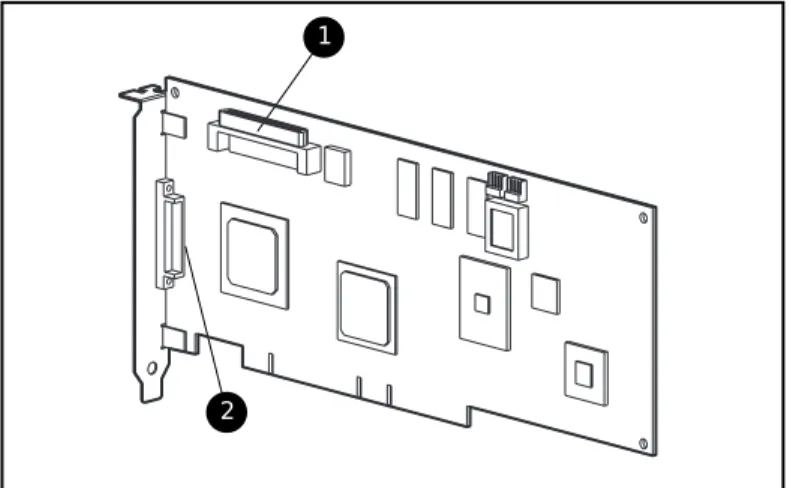
Smart Array 431 Controller
The Smart Array 431 Controller interface to the server is a Peripheral
Component Interface (PCI) bus. The PCI bus is a high-performance, 64-bit bus with multiplexed address and data lines, and includes a parity signal. It provides a high-speed (up to 264 MB/s) path between the system board and the Array Controller. The Smart Array 431 Controller is a PCI Bus Master device and conforms to Rev. 2.2 of the PCI Local Bus Specification.
1
2
Figure 1-1. Smart Array 431 Controller
Major connectors of the Smart Array 431 Controller include: 1 Internal 68-pin Wide SCSI connector
Drive Arrays
RAID technology distributes data across a series of hard drives to unite physical drives into one or more logical drives. Distributing the data makes it possible to access data concurrently from multiple drives in the array, yielding I/O rates faster than non-arrayed drives. Each logical drive in the array may be set to a different fault-tolerant configuration. The Smart Array 431 Controller manages the drive array independent of the host processor.
The Array Configuration Utilities are used to help you configure the hardware in the way that best suits your needs.
CAUTION: It is recommended that any time you move drive arrays or change your configuration you should back up data.
See Appendix D, “Understanding Drive Arrays,” for more information on drive arrays. For information on configuring your drive arrays using Option Rom Configuration for Arrays and Compaq Array Configuration Utility, see Chapter 6, “Array Configuration Utilities.”
Fault Tolerance
Fault tolerance refers to various methods used to protect data from being lost in the event of a hardware failure somewhere in the storage system. Each method has its advantages, so choosing one requires careful planning for your particular requirements.
The fault tolerance methods supported by the Smart Array 431 Controller and the Compaq Array Configuration Utility include:
■ Distributed data guarding (RAID 5)
■ Drive mirroring (RAID 1) or (0+1)
■ No fault tolerance (RAID 0)
■ Further data protection can be achieved by assigning an online spare to any RAID 1 or RAID 5 configuration
See Appendix D, “Understanding Drive Arrays,” for more information on these fault tolerance methods. See Chapter 6, “Array Configuration Utilities,” for information on configuring your system using one of the fault-tolerance methods.
Features 1-5
Drive Movement
An array of drives can be moved from one system to another as long as the relative order of the drives is maintained. For more information, see Chapter 6, “Array Configuration Utilities.”
Read-Cache Memory
The Smart Array 431 Controller has 16-MB of d-RAM used for code data and non-battery backed read cache.
Expanding and Extending Capacity
The Array Configuration Utility makes changing your storage configuration easy, even in fault-tolerant configurations, without requiring a data backup and restore cycle. If you are using Microsoft Windows NT or Novell NetWare operating systems with hot-pluggable drives, storage expansion or extension can be performed online, without shutting down the server operating system. Capacity expansion refers to adding capacity and creating new logical drives. Capacity extension refers to growing existing logical drives.
Online RAID Level and Stripe Size Migration
The Array Configuration Utility also makes reconfiguring a currently configured logical drive to a new fault tolerance (RAID) level or moving an existing logical drive’s stripe size to a new stripe size easy. Both can be done online without disruption to system operation or loss of data. For more information about online RAID level and stripe size migration, see “Array Configuration Utilities,” in Chapter 6.
SCSI Support
The Smart Array 431 controller supports a number of SCSI standards to provide the latest high performance SCSI device support available while also providing compatibility with older SCSI devices. The following SCSI standards are supported:
■ Wide Ultra 3 capable of a 160 MB/s maximum transfer rate
■ Wide Ultra 2 capable of a 80 MB/s maximum transfer rate
LVD and SE Signaling
Both Wide Ultra3 and Wide Ultra2 SCSI devices use Low Voltage
Differential (LVD) signaling on the SCSI bus. LVD allows devices to run at higher speeds and at longer distances. Wide-Ultra SCSI devices use Single Ended (SE) signaling on the SCSI bus, which is an older technology. LVD and SE signaling are not supported concurrently on the same SCSI bus. Therefore, if SCSI devices that supports LVD signaling are placed on the same SCSI bus as SCSI devices that support SE signaling, then the LVD SCSI devices will revert to SE signaling to maintain compatibility. Since the Wide Ultra2 and Wide Ultra3 standards require LVD signaling, this means that those SCSI devices will operate at Wide-Ultra speeds since that is the only standard support by Compaq with SE signaling.
If all of the SCSI devices on the SCSI bus use LVD signaling, they will be compatible with each other. Wide Ultra2 and Wide Ultra3 SCSI devices can coexist and run at their respective maximum speeds per the appropriate SCSI standard.
Maximizing Performance
Compaq recommends using only Wide Ultra2 and Wide Ultra3 SCSI devices on the same SCSI bus for maximum performance. Combining LVD and SE SCSI devices on the same SCSI bus will decrease the overall performance to Wide-Ultra speeds.
Array Configuration Utilities
Options Rom Configuration for Arrays (ORCA)
The Options Rom Configuration for Arrays utility will allow you to configure your array controller. ORCA is designed for those with minimal configuration requirements, and a moderate knowledge level of RAID technology. This utility:
■ Can be started while the server is booting
■ Does not require diskettes or CD-ROM drives to run
■ Can only configure a single logical drive
■ Has minimal control over the physical configuration
■ With certain requirements, can be executed at a later time
Features 1-7
Array Configuration Utility (ACU)
The Compaq Array Configuration Utility is an easy-to-use graphical
configuration utility to help you set up and change drive array configurations. ACU contains configuration Wizards for those with little knowledge of RAID technology, and also has advanced paths for those experienced RAID users. This utility:
■ Requires the SmartStart and Support Software CD to boot
■ Can configure any number of logical drives
■ Has full control over the physical configuration
■ Can be executed at a later time even after other utilities have run
■ Runs online under Microsoft Windows NT 4.0 or Novell NetWare
■ Provides a graphical view of Compaq drive array configurations
■ Helps optimize your array configuration with configuration Wizards
■ Provides express or custom initial configuration
■ Supports RAID 0, RAID 1, RAID 0+1, and RAID 5 configurations
■ Sets drive rebuild priorities
■ Allows online spare (hot spare) configurations
■ Allows separate fault tolerance configuration on a logical drive basis
■ Supports easy capacity expansion and logical drive extension
■ Supports RAID and Stripe-size migration
See Chapter 6, “Array Configuration Utilities,” for details on using these utilities.
Installation Preparation
This chapter provides the following information:
■ Option Kit contents
■ Hardware and software installation guidelines
■ Guidelines for making changes to your current installation
Read this chapter before you begin the installation process. See Chapter 4, “Hardware Installation and Cabling Information,” for Cabling information.
2-2 Compaq Smart Array 431 Controller User Guide
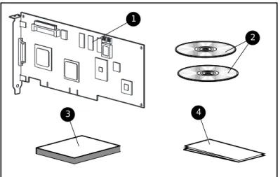
Option Kit Contents
Figure 2-1 identifies the major components included in the Smart Array 431 Controller Option Kit.
2 1
3 4
Figure 2-1. Smart Array 431 Controller option kit
1 CompaqSmart Array 431 Controller
2 Compaq SmartStart and Support Software CD, and Controller Products Documentation (CPD) CD
3 Compaq Smart Array 431 Controller User Guide
4 Compaq Smart Array 431 Controller Quick Hardware Installation
Poster
SmartStart and Support Software CD
The SmartStart and Support Software CD contains the software to configure the Smart Array 431 Controller and to install the operating system drivers.
Controller Products Documentation CDs
The Controller Products Documentation CDs contain user documentation that allows you to view, search, and print information for Compaq controller products.
Hardware and Software Installation
Guidelines
For first-time installations, the following steps must be performed in the order listed. If you are upgrading from an existing array controller, see the following section, “Guidelines for Making Changes to Current Installation.”
Table 2-1
Smart Array 431 Controller Installation Steps
Step Function Go to:
1 Update the server firmware Chapter 3 2 Hardware installation and cabling Chapter 4 3 System Configuration Chapter 5 4 Decide on a fault tolerance method Appendix D 5 Configure your drive arrays Chapter 6 6 Install drivers for your operating
system
Chapter 7
IMPORTANT: If the controller is purchased separately, make sure that the system boots properly after Smart Array 431 Controller installation by updating the server firmware
2-4 Compaq Smart Array 431 Controller User Guide
Guidelines for Making Changes to Current
Installation
This section provides guidelines for:
■ Installing multiple Smart Array 431 Controllers
■ Installing or replacing drives in your Compaq server
■ Determining maximum storage capacity
■ Changing the fault tolerance
■ Moving drives
■ Moving arrays
■ Restoring an array to its original controller
Installing Multiple Smart Array 431 Controllers
When you install more than one Smart Array 431 Array Controller in the same server, the following considerations apply:
■ Each Smart Array 431 Controller has one SCSI channel, which supports up to 15 drives.
■ Each SCSI channel has its own set of unique SCSI IDs (from 0 to 6 and 8 to 15). You must assign a unique ID for each peripheral on the bus. A hot-pluggable ID is assigned automatically. Non-hot-pluggable drives require manual SCSI ID selection.
Drive Considerations
If you will be installing or replacing drives in your Compaq server, keep in mind that:
■ Drives may be Wide Ultra3 SCSI, Wide Ultra2 SCSI or Wide-Ultra SCSI-3. To maximize performance, the drives must all be the same type.
■ Drives on a single SCSI bus may be internal or external, but not both.
■ Drives should not contain termination. Compaq servers and internal cabling provide the required termination of the SCSI bus.
■ For the most current list of Compaq hard drives supported by the Smart Array 431 Controller, refer to the website,
www.compaq.com/products/StorageWorks/harddiskstorage.
■ Drives should be of the same capacity to provide the greatest storage space efficiency when drives are grouped together into the same drive array.
Determining Maximum Storage Capacity
The maximum number of controllers and drives supported depends on several factors. To determine the number of drives supported by your server, refer to the Setup and Installation, or Reference Guide that accompanied your server. Server specifications are also available at www.compaq.com. For information on expanding storage capacity, see the section in Appendix D, “Adding Storage Capacity.”
2-6 Compaq Smart Array 431 Controller User Guide
Expanding the Capacity of an Array
Provided below is an overview of the procedures to expand the capacity of an array.
1. Back up data. Although data should not be lost during a normal capacity expansion, it is a good idea to back up all data in the array that you will be expanding. This backup may also be used to return to the original configuration if necessary.
2. Add drives. If you are using a server or storage system that does not support hot-pluggable drives, you will need to power down the server or storage system to add new drives. If you are using a server or storage system that does support hot-pluggable drives, do not power down the system or take it off-line. Simply plug the new drives into vacant bays. 3. Configure drive array. Refer Chapter 6, “Array Configuration Utilities”
for instructions reconfiguring your drive array to make use of the added capacity. If your operating system supports it, you may run the Array Configuration Utility online.
4. Restore data. If necessary restore the data you backed up in step 2.
Your system will automatically create logical drives and redistribute data in the array as necessary to expand the array.
Changing the Fault Tolerance
To change fault tolerance:1. Decide on a fault tolerance method. Review Appendix D,
“Understanding Drive Arrays,” and choose the fault tolerance method that best suits your needs.
2. Back up data. Back up all data in the logical drive that you will be changing. Although data loss is not anticipated while changing fault tolerance, it is recommended that you back up data before moving drives.
3. Configure the drive array. Go to Chapter 6, “Array Configuration Utilities,” for information on modifying your drive array with the new fault tolerance method.
Moving Drives Offline
Drives can be moved to alternate SCSI ID positions on the same array controller as long as no drives are failed.
To move drives, the following conditions must be met:
■ Controller firmware should be the revision that shipped with your unit or higher. Refer to the Smart Start and Support Software CD included in this kit.
■ System power is OFF (includes all system components).
■ The move will not result in more than 15 physical drives connected to a single SCSI bus, or more than 32 logical drives (volumes) connected to a single controller.
■ No failed drives identified. The array should be in its original configuration with no active spare drives.
■ Drives in each array must maintain the same relative positions before and after drive movement as shown in Figure 2-2.
When the above conditions are met, follow these steps to move drives: 1. Power system OFF.
2. Move drives.
3. Power system ON. A 1724 POST message should indicate that drive positions were changed and the configuration was updated.
CAUTION: If the system displays a 1785 (Not Configured) POST message, turn the system off immediately to avoid data loss and return the drives to their original locations.
4. Run Array Configuration Utility to view the new drive configuration (optional).
Chapter
3
Updating the Firmware
The ROMs on all Compaq servers and most Compaq options can be updated easily. This is done by flashing the ROM using a special Compaq utility called ROMPaq, which replaces the existing contents of the ROM with another version stored in a disk file. This is a convenient way to distribute new firmware to keep Compaq products updated with the latest capabilities. There are two ROMPaq utilities:
System ROMPaq for updating the system ROM in all Compaq servers
supporting Flash ROM. Use System ROMPaq when installing a new Smart Array 431 Controller in a Compaq server to be sure that the server can utilize all the
capabilities of the Smart Array 431 Controller.
Options ROMPaq for updating the onboard ROM on all Compaq options that
support flashing. Use Options ROMPaq when new versions of the Smart Array 431 Controller firmware or SCSI drive firmware become available to take advantage of expanded capabilities.
IMPORTANT: Before you install the new Smart Array 431 Controller in your server, you must run System ROMPaq to update the system firmware. Use the following instructions to create diskettes with the latest version of System ROMPaq from the Compaq SmartStart and Support Software CD (supplied with the Smart Array 431 Controller).
ROMPaq Diskettes
The ROMPaq utilities must be run from diskette(s). The latest version of the ROMPaq diskettes may be created from the Compaq SmartStart and Support Software CD that was supplied in the Smart Array 431 Controller Option Kit. We recommend that you initially use this version of ROMPaq because it supports your new Smart Array 431 Controller.
Materials Needed
You will need the following items to create ROMPaq utility diskette(s):
■ Compaq SmartStart and Support Software CD (supplied in the Smart Array 431 Controller Option Kit)
■ Three to five blank diskettes (for System ROMPaq) or 10-15 blank diskettes (for Options ROMPaq)
■ Access to a server or workstation with a bootable CD-ROM drive. This may be the system in which you are installing the Smart Array 431 Controller.
Creating Diskettes
To create ROMPaq diskettes:
1. Boot the server from the Compaq SmartStart and Support Software CD. 2. From the Compaq Diskette Builder screen, select Create Software
Diskettes from CD.
3. From the Diskette Builder screen, scroll through the list and select one of the following three ROMPaq selections:
q System ROMPaq Firmware Upgrade Diskette for Compaq ProLiant Servers
q System ROMPaq Firmware Upgrade Diskette for Compaq Systempro/XL and Compaq ProSignia Servers
q Options ROMPaq
Updating the Firmware 3-3
Running System ROMPaq
System ROMPaq is used to update the firmware in Compaq servers. The Smart Array 431 Controller has enhanced drive array capabilities; many existing servers may not be able to take advantage of these capabilities without updated firmware. Since it is difficult to determine when the firmware needs to be updated, Compaq recommends that you run the latest System ROMPaq on all servers when installing a new Smart Array 431 Controller. If you purchased your server with the Smart Array 431 Controller already installed, you do not need to run System ROMPaq at the time of server installation.
CAUTION: If you are replacing an existing array controller, such as the Compaq SMART-2SL Array Controller, with the Smart Array 431 Controller, the system may not boot after hardware installation. It may not boot if the old array controller was the primary controller containing the boot disk.
To avoid this problem, run System ROMPaq before you make the hardware installation. This ensures that the server will recognize the Smart Array 431 Controller and not hang up on boot.
To run System ROMPaq:
1. Place the System ROMPaq diskette in the server diskette drive. 2. Boot the server by turning on the power.
3. Press Enter at the Welcome screen.
4. At the Select A Device screen, select the server from the list of the programmable devices. This may be the only item in the list. Press Enter. 5. At the Select An Image screen you will see:
Device to reprogram: your server
Current ROM revision: date of existing ROM version Select Firmware Images: date of latest ROM version
6. Review the information on the Caution screen:
Device to reprogram: your server
Current ROM revision: date of existing ROM version Selected ROM revision: date of ROM version to be installed
Press Enter to reprogram the system ROM or Esc to discontinue reprogramming and return to the Select An Image screen.
7. “Reprogramming Firmware” indicates that the system ROM is being reprogrammed. DO NOT INTERRUPT THIS PROCESS.
CAUTION: Do not interrupt this cycle. Interrupting the ROM
reprogramming will leave the firmware in an unknown state. If this happens you may not be able to boot the server. You will be notified when reprogramming is completed.
8. When ROMPaq is finished reprogramming the system ROM, press Esc to exit the System ROMPaq Utility.
9. Remove the System ROMPaq diskette and reboot the server by cycling the power (cold boot).
If you have not installed your new Smart Array 431 Controller, you can do so at this time.
Running Options ROMPaq
Options ROMPaq is used to update the firmware on Compaq options. Use Options ROMPaq to update the capabilities of the Smart Array 431 Controller and drives whenever an updated version is available in the future. Since it is difficult to determine when to update the firmware, Compaq recommends that you keep current with the latest revisions, which can be found on the Compaq website.
The Smart Array 431 Controller firmware version included on the Compaq SmartStart and Support Software CD has already been installed on that controller, so you do not need to update immediately. However, if you have older Smart Array 431 Controllers or other Compaq options, you may want to create the Options ROMPaq diskettes and check that the firmware on these options are at the latest revision.
Updating the Firmware 3-5
To run Options ROMPaq:
1. Locate the diskette containing the Options ROMPaq and place it into the server floppy drive.
2. Boot the server by turning on the power. 3. Press Enter at the Welcome screen. 4. At the Select A Device screen select:
ALL COMPAQ Smart Array 431 Controller(s)
from the list of programmable devices. Press Enter.
5. If the ROM firmware in the Smart Array 431 Controller is the same or newer than that on the Options ROMPaq diskette, this message displays:
The ROM image files found for the device selected are not newer than the current ROM image
Press Enter to go to step 9. OR
If the ROM firmware in the Smart Array 431 Controller is older than that on the Options ROMPaq diskette, the Select An Image screen displays:
Device to reprogram: ALL COMPAQ SMART 431 Controller(s) Current ROM revision: COMPAQ SMART 431 Controller x.xx Select Firmware Images: COMPAQ SMART 431 Controller y.yy
Press Enter.
6. Review the information on the Caution screen:
Device to reprogram: ALL COMPAQ SMART 431 Controller(s) Current ROM revision: COMPAQ SMART 431 Controller x.xx Selected ROM revision: COMPAQ SMART 431 Controller y.yy
7. Press Enter to reprogram the Smart Array 431 Controller ROM or Esc to discontinue the reprogramming and return to the Select An
Image screen.
Reprogramming Firmware
indicates that the Smart Array 431 Controller ROM is being reprogrammed. DO NOT INTERRUPT THIS PROCESS.
CAUTION: Do not interrupt this cycle. Interrupting the ROM reprogramming will leave the firmware in an unknown state. If this happens you may not be able to reprogram the ROM and the Smart Array 431 Controller ROM may have to be replaced. You will be notified when reprogramming is completed.
8. When Options ROMPaq is finished reprogramming the Smart Array 431 Controller ROM, press Enter if you want to reprogram another Compaq option. Repeat steps 4 through 7.
9. If you are finished with reprogramming options, press Esc to exit the ROMPaq Utility.
10. Remove the Options ROMPaq diskette and reboot the server by cycling the power (cold boot).
The Smart Array 431 Controller ROM has been updated; you can take advantage of the new or increased capabilities, if any, available with the new firmware.
Chapter
4
Controller Installation and Cabling
Information
This chapter provides instructions to install and connect a Compaq Smart Array 431 Controller into Compaq Servers. See Table 2-1 for supported server information.
Table 4-1
Servers Supported with the Compaq Smart Array 431 Controller
Compaq ProLiant Servers (Tower) 1200, 1600,2500, 3000, 5000, 5500, 6000, 6500, 7000, 8000, 8500 Compaq ProLiant Rack-Mountable Servers 1600R, 1850R, 2500R, 3000R, 6000R,
6500R, 7000R, 8000R, 8500R Compaq StorageWorks Enclosure 4200 4214R, 4214T
Note: For the most recent list of supported servers, refer to your Setup and Installation Guide or Reference Guides or visit the Compaq Website at:
www.compaq.com/products/servers/servername/cableguide.html
Tools Needed
■ Torx T-15 screwdriver
Preparing the Server
To prepare the server for Smart Array 431 Controller installation: 1. Perform a normal system shutdown.
CAUTION: If you will be moving non-arrayed SCSI drives to the Smart Array 431 Controller, you must first back up all of your data. Data is not preserved when drives are moved between array controllers and non-array controllers.
CAUTION: In systems using external data storage, be sure the server is the first unit powered down and the last to be powered back up. This will ensure that the system will not erroneously mark the drives as “failed.”
2. Turn OFF the server.
3. Turn OFF any peripheral devices attached to the server.
4. Unplug the AC power cord from the outlet, then from the server.
IMPORTANT: If you will be replacing an existing Smart Controller with a new Smart Array 431 Controller, refer to the External Cabling section later in this chapter to determine the external cabling requirements.
5. Disconnect any peripheral devices from the server.
WARNING: To reduce the risk of personal injury from hot surfaces, allow the internal system components and hot-plug hard drives to cool before touching.
6. Remove the access panel.
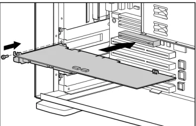
Installing the Smart Array 431 Controller
Use the following procedure to install the Smart Array 431 Controller into a Compaq Server.
1. Select an available PCI slot.
2. Remove the slot cover. Save the retaining screw, if necessary.
CAUTION: Electrostatic discharge (ESD) can damage electronic components. Be sure you are properly grounded before beginning this procedure. See Appendix B for ESD information.
3. Press the Smart Array 431 Controller firmly into the slot so the contacts on the board edge seat fully in the system board connector.
Controller Installation and Cabling Information 4-3
4. Secure the board in place with the retaining screw, if necessary.
Figure 4-1. Installing the Smart Array 431 Controller into a Compaq server
NOTE: Your server’s appearance may differ slightly from the server illustrated in Figure 4-1.
SCSI Port Utilization
This section provides cabling information for installing and changing the SCSI cabling within the server. The Smart Array 431 Controller may be connected to both SCSI hard drives located in external storage units and to SCSI hard drives located internally in the server. The Smart Array 431 Controller has one independent SCSI port that can be utilized by:
■ Internal hot-pluggable drives
■ Internal non-hot-pluggable drives
SCSI Termination
All SCSI buses require termination on both ends of the bus to prevent signal degradation. The Smart Array 431 Controller supplies the termination on the origination end of the SCSI bus. Termination for the opposite end of the bus is either provided by the internal SCSI cable or by the backplane. Therefore, individual SCSI drives in Compaq servers should not contain bus termination. External SCSI devices must also provide termination for the SCSI bus. This is supplied in Compaq ProLiant Storage systems. Therefore, individual SCSI drives in Compaq ProLiant Storage systems should not contain bus termination.
SCSI IDs
The Smart Array 431 contains one SCSI bus (port), which supports up to 15 drives. Peripherals attached to either connector must have a unique SCSI ID in the range of 0 to 6, 8 to 15. SCSI IDs on all peripherals are set manually with switches or jumpers on the device itself or set automatically on Compaq products that support hot-pluggable drives. The SCSI ID determines the device’s priority when attempting to use the SCSI bus. The highest priority, SCSI ID 7, is reserved for use by the controller.
Internal Cabling for Compaq Servers
Internal Drives and Cabling
IMPORTANT: Determine if your storage device is a hot-pluggable or a non-hot-pluggable drive.
IMPORTANT: Port 1 cannot be used for both internal and external drives concurrently
Hot-Plug Drives
■ Install the hot-plug drives into the server hot-plug drive cage. NOTE: For additional hot-plug drive installation instructions, consult the original installation information that accompanied your drives.
■ Drives need not be the same capacity, except for maximum space efficiency when grouped together in the same array.
Controller Installation and Cabling Information 4-5
■ Use the internal point to point SCSI cable provided with your server.
■ Attach the point to point SCSI cable from Port 1 of the Smart Array 431 Controller to the hot-plug drive cage.
Non-Hot-Plug Drives
■ Install the non-hot-plug drives into the server’s removable media bays. NOTE: For additional non-hot-plug drive installation instructions, consult the original installation documentation that accompanied your drives.
■ Drives need not be of the same capacity, except for maximum space efficiency when grouped together in the same array.
■ You must manually set the SCSI ID on each drive to a unique value in the range of 0 to 6 for each SCSI bus. Consult the documentation that came with the drive for instructions on setting the SCSI ID.
■ Attach the multi-device SCSI cable:
a. If drives are Wide-Ultra SCSI-3 use the multi- device SCSI cable that was provided with your server. Attach the multi- device SCSI cable from Port 1 or the Smart Array 431 Controller to the non-hot-plug hard drives.
b.If drives are Wide Ultra3 or Wide Ultra2 SCSI, the multi-device cable may have been provided with your server. If additional cables are needed, order cable option kit, part number 104936-B21.
NOTE: This cable is equipped to terminate Wide-Ultra SCSI-3, Wide Ultra3 SCSI, or Wide Ultra 2 SCSI drives.
CAUTION: Cable assembly 269157-006 that is included in option kit 104936-B21 is REQUIRED with Wide Ultra2 drives. Not using this cable may result in inoperability of your drives.
■ Attach the multi-server cable from Port 1 of the Smart Array 431 Contrller to the non hot-plug hard drives.
External Cabling for Compaq Servers
This section provides cabling instructions for connecting the external Port of the Compaq 431 Smart Array Controller to Compaq ProLiant Storage Systems.
External SCSI Connections
If you are connecting the Smart Array 431 Controller to a Compaq Storage Enclosures, use an external Offset VHDCI to Wide SCSI cable.
IMPORTANT: Port 1 cannot be used for both internal and external drives concurrently
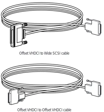
External Cables
All Compaq ProLiant Storage System Tower models include 6 foot external SCSI cables, and all Compaq ProLiant Storage System Rack-Mount models include 12 foot external SCSI cables. See Figure 4-2 and Table 4-2 for details.
Offset VHDCI to Wide SCSI cable
Offset VHDCI to Offset VHDCI cable
Figure 4-2.External SCSI cables for the Compaq Smart Array 431 Controller
1 Offset VHDCI to Wide SCSI cable
2 Offset VHDCI to Offset VHDCI cable
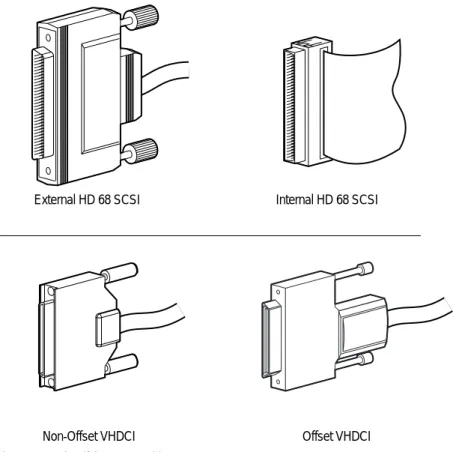
IMPORTANT: Check the connector type on your storage device to identify the appropriate interconnects needed.
Controller Installation and Cabling Information 4-7
External HD 68 SCSI Internal HD 68 SCSI
Non-Offset VHDCI Offset VHDCI
Figure 4-3. Identifying SCSI Cable Connectors
External SCSI cables are supplied with all of the following Compaq Storage Enclosures:
■ ProLiant Storage System /U1 (Wide-Ultra SCSI-3)
■ ProLiant Storage System /U2 (dual bus) (Wide-Ultra SCSI-3)
■ ProLiant Storage System /UE (Wide-Ultra SCSI-3) (Wide Ultra 2SCSI)
■ StorageWorks Enclosure Model 4214R (Wide Ultra 2SCSI)
Table 4-2
External SCSI Cables for Compaq Enclosures
Cable Description Option Kit Number Cable Assembly Number
External 6-ft. Offset VHDCI to Wide SCSI cable
341176-B21 313375-001
External 12-ft.Offset VHDCI to Wide SCSI cable
341177-B21 313375-002
External 6-ft. Offset VHDCI to Offset VHDCI SCSI cable
341174-B21 313374-001
External 12-ft.Offset VHDCI to Offset VHDCI SCSI cable
341175-B21 313374-002
Note: If additional cables are required, Order the Option Kit Number.
IMPORTANT: If you will be replacing an existing Smart Controller with the new Smart Array 431 Controller without reconfiguring the arrays, it is recommended that all of the drives are connected exactly as they were on the old controller (port 1 to port 1, controller 1 to controller 1, and so on).
External Cabling Instructions
One SCSI port may be available for connection to external storage devices, depending on whether or not internal drives are connected to the Smart Array 431 Controller.
1. On the rear of the server, connect the Offset VHDCI SCSI end of the cable to the Compaq Smart Array 431 Controller.
2. Tighten the screws on the cable.
Controller Installation and Cabling Information 4-9
Completing the Installation
Replace the access panel and secure it with the thumbscrews, as required.
NOTE: The server will not operate with the access panel removed. This is necessary to protect thermally sensitive components by providing the proper air flow through the server and to prevent contact with hazardous energy during servicing.
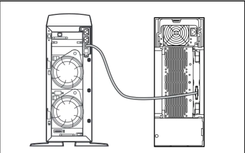
Figure 4-4. External cabling on ProLiant Tower Storage Systems
NOTE: A Rack-Mountable device configuration will differ in appearance.
Chapter
5
Running the System Configuration
Utility
The Compaq System Configuration Utility is used to configure the hardware installed in or connected to the server. This utility allows the server to know how each piece of hardware is to be handled when communicating with it. The System Configuration Utility performs a wide range of configuration activities, including the following:
■ Configures PCI boards automatically
■ Provides switch and jumper settings
■ Resolves resource conflicts in areas such as memory, port addresses, and interrupts (IRQs)
■ Manages the installation of memory, processor upgrades, and mass storage devices such as hard drives, tape drives, and diskette drives
■ Sets and stores power-on features like date and time
■ Stores configuration information in nonvolatile memory
■ Assists in the installation of the operating system
System Configuration Utility on CD
The Compaq System Configuration Utility can be run directly from the Compaq SmartStart and Support Software CD supplied with the Smart Array 431 Controller Option Kit and with the Compaq server. You may already have a version of the System Configuration Utility in the system partition of the boot disk; however, it must be version 4.3 or later to support the 431. To guarantee compatibility and support, use the version of the utility supplied with the Smart Array 431 Controller.
If your server does not have a bootable CD-ROM drive, you can create diskettes of the latest version of the System Configuration Utility from the Compaq SmartStart and Support Software CD. See the following section, “System Configuration Diskettes,” for instructions on creating these diskettes. If your server has a bootable CD-ROM drive, proceed to “Running the System Configuration Utility.”
System Configuration Diskettes
The latest version of the Compaq System Configuration Utility may be created from the Compaq SmartStart and Support Software CD that was supplied in the Smart Array 431 Controller Option Kit.
Materials Needed
You will need the following items to create Compaq System Configuration Utility diskettes:
■ Compaq SmartStart and Support Software CD (supplied in the Smart Array 431 Controller Option Kit)
■ At least four blank diskettes
■ Access to a server or workstation with a bootable CD-ROM drive. This may be the system in which you are installing the Smart Array 431 Controller.
Creating Diskettes
To create System Configuration Utility diskettes:
1. Boot the computer from the Compaq SmartStart and Support Software CD. 2. From the main menu screen, select Create Support Software.
3. Scroll through the list and select Compaq System Configuration Utility. 4. Follow the instructions on the screen to create the utility diskette(s).
Running the System Configuration Utility 5-3
Starting the System
Configuration Utility
To start the System Configuration Utility:
1. Place the Compaq SmartStart and Support Software CD in the server CD-ROM drive.
or
Place the System Configuration Utility diskette 1 in the server diskette drive.
2. Reboot the server.
During the boot process, several messages display. Among these will be a notice that one or more Smart Array 431 Controllers were detected. 3. If prompted, press F1 to resume booting.
4. If you are using the Compaq SmartStart and Support Software CD, select Run the System Configuration Utility from the main menu screen.
5. If you are given a choice of Auto Configuration, choose Yes.
The system loads configuration files for all detected devices. 6. In the Configuration Complete screen, be sure to choose Review or
Modify Hardware Settings.
From the next screen, Steps In Configuring Your Computer, select Step 3: View or Edit Details.
1. The View Or Edit Details screen is where you will set the Smart Array 431 Controller(s) configuration parameters. Scroll to the option slot for the first Smart Array 431 Controller and set each parameter according to the information in the next section, “Configuring the Controller.”
Configuring the Controller
Edit these parameters for the Smart Array 431 Controller:
Controller Order
Press Enter to select the parameter to edit.
To help you make the correct selections, a brief explanation of the parameters follows.
Controller Order
Select the order in which you want this Smart Array 431 Controller to be recognized. All hard disk controllers, including the integrated controller on the system board, must be assigned a unique order number.
First The primary disk controller that contains the boot disk.
The first disk drive on this controller is the one that the server will boot from.
Second The second disk controller
...
Eighth The eighth disk controller.
When installing a Smart Array 431 Controller, you must determine if the boot disk is to be handled by a Smart Array 431 Controller or the integrated SCSI controller. If this Smart Array 431 Controller will be the primary controller, choose First; a Configuration Changes screen is presented, indicating that if you accept this change, the integrated SCSI controller will be changed automatically to Second. Press Enter to accept these changes.
If you want the order of the integrated SCSI controller to be something other than Second, scroll (usually down) to the Embedded Compaq Integrated Controller and set the Controller Order manually, as described above. When installing a Smart Array 431 Controller in a system with an existing array controller, you can either place the new controller at the end of the controller order or reorder the controllers. Reordering changes the current drive letter assignments for all drives on the system. To avoid changing the drive letter assignments, place the new controller at the end of the controller order and do not create a primary partition on any of the added disks. System hardware configuration is complete. Go to Chapter 6, “Array Configuration Utilities,” to configure drive arrays.
Chapter
6
Array Configuration Utilities
Compaq has provided two different mechanisms for configuring your array controller depending on your unique requirements. The decision as to which utility to use should be based on your knowledge level of RAID technology and how much control you need over the physical configurations. The configuration utilities are:
■ Option Rom Configuration for Arrays (ORCA)
■ Array Configuration Utility (ACU)
Selecting the Correct Utility
You can use the following information to determine which utility best meets your configuration needs.
Option Rom Configuration for Arrays (ORCA)
■ Is targeted for those who are more experienced with RAID technology
■ Can be started when the server is booting
■ Does not require any diskettes or CDs to run
■ Can only configure a single logical drive
■ Has minimal control over the physical configuration
■ Can be executed at a later time if certain requirements are met
Array Configuration Utility (ACU)
■ Has configuration Wizards for novices and advanced paths for experienced RAID users
■ Requires the SmartStart and Support Software CD to boot
■ Can configure any number of logical drives
■ Has full control over the physical configuration
■ Can be executed at a later time even after other utilities have run
■ Runs online under Microsoft Windows NT 4.0 or Novel NetWare (using CPQONLIN.NLM)
Option Rom Configuration for Arrays
This utility executes out of the Option ROM that is supplied with the array controller. It is designed for those who are more experienced with RAID technology, but have minimal configuration requirements.
Functionality
ORCA provides:
■ Creation of a single logical drive
■ Deletion of a single logical drive
■ RAID level selection
■ Assignment of an online spare with the created logical drive
Restrictions
ORCA’s restrictions are:
■ If more than one logical drive exists on the array controller, the utility cannot be started.
■ If there are more than eight physical drives attached to the array controller, the utility cannot be started.
■ Logical drive settings (stripe size) and controller settings are not available. Use the ACU to access these settings.
Array Configuration Utilities 6-3
Starting the Option Rom Configuration for Arrays
Utility
Part of the power-on sequence of a computer system if the Power On Self Test (POST). During this process any array controllers in the system will be initialized. Any array controller that supports ORCA will provide a prompt to the computer system console as part of the initialization process, providing all of the restrictions are met.
If there are no configured logical drives on the array controller then this prompt will wait 15 seconds before bypassing ORCA and continuing with POST.
If there is one logical drive configured on the array controller then this prompt will wait 5 seconds before bypassing ORCA and continuing with POST. If the ORCA starting requirements are not met, then the prompt will not appear and the system will continue with POST.
While the prompt is waiting on the console, you can: Press F10 to start the ORCA utility,
Or
Press the ESC key to bypass OCRA immediately.
Compaq Smart Array 431 Controller (ver 1.00)
Press <F10> to run the Option Rom Configuration for Arrays utility Press <Esc> to skip configuration and continue
Figure 6-1. Initial Start screen – Option Rom Configuration for Arrays
Creating a Logical Drive
If there are no logical drives configured on the array controller, you will be given the option to create one. All of the available physical drives will b e used for the configuration. If you do not wish to use all of the physical drives in your configuration, you must power off the system and disconnect those physical drives.
After selecting the appropriate RAID level and online spare; press F10 to accept the configuration.
Deleting a Logical Drive
If there is a single existing logical drive already configured on the array controller, you will be given the option to delete the logical drive.
■ Press F3 to delete the logical drive And
■ ESC to exit the utility
Confirmation Screen
The Confirmation screen is shown as a pop-up panel on top of the last screen.
Figure 6-2. Confirmation screen
Array Configuration Utility
This section provides instructions for using the Compaq Array Configuration Utility; and it describes methods (wizards) you can use to configure your controller quickly and easily. This section is divided into seven sub-sections, listed below. You should read the first five subsections and use the last two as reference material when needed.
■ Before You Begin
■ Starting the Compaq Array Configuration Utility
■ Configuration Wizards
■ Online Help
■ Configuration Procedures
■ Array Configuration Utility screens
■ Errors and Warnings
You have selected a logical drive with a total data size of 8.6GB and RAID 5 fault tolerance. An Online Spare has also been selected.
Press <F10> to save the configuration and exit Press <Esc> to cancel
Array Configuration Utilities 6-5
The Array Configuration Utility, which is located on the SmartStart and Support Software CD, is a graphics-based application that helps you configure the Compaq Smart Array 431 Controller. You can use the Array Configuration Utility to configure the Smart Array 431 Controller initially or to reconfigure your array controller.
The Array Configuration Utility provides the following configuration benefits:
■ Illustrates the controller configuration in an easy-to-understand graphical format
■ Provides descriptions of various configuration errors
■ Contains configuration wizards that walk you through the configuration process
■ Suggests optimal configuration and fault tolerance for unconfigured controllers
Before You Begin
During a first-time installation and configuration of the Smart Array 431 Controller, you should:
1. Install the Smart Array 431 Controller board. 2. Update the system ROM with System ROMPaq.
3. Run Option ROMPaq to update the controller firmware, option ROM, and drive firmware.
4. Run the System Configuration Utility to verify the controller order settings.
5. Decide which fault-tolerance method and array configuration you want to use.
Starting the
Array Configuration Utility
You can access and start the Array Configuration Utility in two ways: from the SmartStart and Support Software CD or from online.
SmartStart and Support Software CD
You can run the Array Configuration Utility directly from the SmartStart and Support Software CD.
1. Insert the SmartStart and Support Software CD in the CD drive and power up the server. A menu is displayed.
2. Select the Array Configuration Utility.
3. After completing the configuration, remove the CD and restart the server.
Accessing Online
If the server you are configuring is running Microsoft Windows NT or Novell NetWare, you can install and run the Array Configuration Utility online.
Windows NT
When you install the Windows NT Software Support Diskette (SSD), it prompts you to insert the Array Configuration Utility diskettes to install the utility. A program icon is created automatically. Select the icon to run the Array Configuration Utility. The Windows NT online Array Configuration Utility requires that at least one logical drive be previously configured while offline.
NetWare
The Compaq Array Configuration Utility for NetWare (CPQONLIN.NLM) is available on the NetWare Programs from Compaq (NPFC) diskettes in the \DRV_ARRY directory. Generate the NPFC diskettes using the Diskette Builder feature in SmartStart. The NPFC diskettes have an ARRAY.RDM readme file to access instructions on loading and using CPQONLIN.NLM.
Array Configuration Utilities 6-7
Configuration Wizards
When you start the Array Configuration Utility, the software checks the configuration of each Smart Array 431 Controller board and its drive arrays. If the arrays are unconfigured or if the configuration is less than optimal, the configuration wizard takes over to guide you through the configuration process. The configuration wizard recognizes the following conditions:
■ Unconfigured controller - When the Array Configuration Utility detects an unconfigured controller, the configuration wizard steps you through the controller configuration process.
■ Unused physical drives - When the Array Configuration Utility detects unused physical drives, the configuration wizard provides an easy way to create a new array. The “capacity expansion” capability of the Smart Array 431 allows the Array Configuration Utility to add new physical drives to an existing array without destroying data on the existing logical drives.
■ Unused space on an array - If the Array Configuration Utility detects unused capacity in an array, the configuration wizard steps you through the process of configuring the space into one or more logical drives.
Online Help
Press the F1 key or click the Help button to activate context-sensitive help for each screen. A status bar at the bottom of the screen also provides immediate help messages describing the current selection.
Configuration Procedures
Creating a New Array
If you are configuring a new array, the configuration wizard leads you through the process. If you want to bypass the wizard, use the following procedures to create your array.
Creating a New Array—Procedure
Creating a new array involves the following general steps: 1. Choosing a controller for the array.
2. Grouping physical drives of the same size into an array. 3. Subdividing the array into one or more logical drives.
The following example illustrates using the Array Configuration Utility to carry out these steps.
Creating a New Array—Example
For this example, make the following assumptions:
❏ Four 4.3-GB drives and two 9.1-GB drives are connected to the Smart Array 431 Controller.
❏ There will be two arrays. Array A consists of three 4.3-GB drives, with the fourth 4.3-GB drive used as a spare. Array B is the two 9.1-GB drives.
❏ The fault tolerance method for all logical drives on Array A is RAID 5, Distributed Data Guarding. The fault tolerance method for all logical drives on Array B is RAID 1, Drive Mirroring.
Step 1: Choosing a controller for the array
1. In the Array Configuration Utility Main Configuration Screen, select the Controller Select box. You can also select Controller/Select...from the main menu.
2. Select one of the listed Smart Array 431 controllers.
Array Configuration Utilities 6-9
3. Click the Controller Settings button shown in Figure 6-4.
Figure 6-4. Controller buttons
The Controller Settings screen is displayed, as shown in Figure 6-5. 4. Select the correct operating system on the Controller Settings screen.
Step 2: Grouping physical drives of the same size into an array
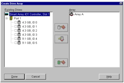
1. Click the Create Array... button. The Create Drive Array screen is displayed.
Figure 6-6. Create Array screen
2. Select the three drives you want to make up the array from the drives on the left. Always group physical drives of the same size. The Smart Array 431 Controller treats all the drives as the same size as the smallest drive in the same array. If you mix drive sizes, the capacity of the largest drive is wasted.
For this example select the following drives: Port 1:SCSI ID 0
Port 1:SCSI ID 1 Port 1:SCSI ID 2
Click the Assign Drive(s) to Array button.
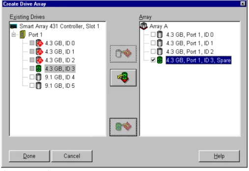
3. Select the drive at Port 1:SCSI ID 3 and click the Assign Spare to Array button. The right side of the Create Array screen should now look similar to the following figure.
Array Configuration Utilities 6-11
Figure 6-7. Example Array A
NOTE: The same spare drive may be assigned to multiple arrays. However, spare drives should have the same or greater capacity as the drives in the array.
4. Click the Done button to return to the Main Configuration screen. The Logical Configuration View area should now look similar to the following figure.
Figure 6-8. Example Array - Logical Configuration View with 1 Array
5. Select the controller, and then select the Create Array button to create Array B.
6. Assign both 9.1-GB drives to the array. Click the Done button.
Step 3: Creating logical drives across the physical drives.
When creating a logical drive, you can select a fault tolerance (RAID level) option and provide information regarding the drive size and array accelerator.
1. Select Array A or the Unused Space icon under Array A in the Logical Configuration View.
2. Click the Create Logical Drive button. A screen similar to the following figure displays.