ORiNOCO AP-600
User Guide
© 2003 Proxim Corporation. All rights reserved. Covered by one or more of the following U.S. patents: 5,231,634; 5,875,179; 6,006,090; 5,809,060; 6,075,812; 5,077,753. This user’s guide and the software described in it are copyrighted with all rights reserved. No part of this publication may be reproduced, transmitted, transcribed, stored in a retrieval system, or translated into any language in any form by any means without the written permission of Proxim Corporation.
Trademarks
ORiNOCO is a registered trademark, and Proxim, and the Proxim logo are trademarks of Proxim Corporation. All other trademarks mentioned herein are the property of their respective owners.
ORiNOCO AP-600 User’s Guide 65959/A
Software v2.3 June 2003
Contents
1 Introduction . . . .11
Document Conventions . . . 11
Introduction to Wireless Networking . . . 11
Guidelines for Roaming . . . 12
IEEE 802.11 Specifications . . . 13
Management and Monitoring Capabilities . . . 13
HTTP Interface . . . 13
Command Line Interface . . . 13
SNMP Management . . . 14
2 Getting Started . . . .15
Prerequisites . . . . 15
Product Package . . . 16
MiniPCI Upgrade Kits . . . 16
System Requirements . . . 16
Hardware Installation . . . 17
Initialization . . . 21
ScanTool . . . 21
ScanTool Instructions . . . 21
Setup Wizard . . . 23
Setup Wizard Instructions. . . 23
Download the Latest Software . . . 27
Setup your TFTP Server . . . 27
Download Updates from your TFTP Server using the Web Interface . . . 27
Download Updates from your TFTP Server using the CLI Interface . . . 27
Additional Hardware Features . . . 28
Mounting Options. . . 28
Desktop Mount . . . 28
Wall Mount . . . 28
Ceiling Mount . . . 30
Installing the AP in a Plenum. . . 31
Active Ethernet . . . 32
LED Indicators . . . 32
3 Status Information . . . .34
Logging into the HTTP Interface . . . 34
System Status . . . 35
4 Advanced Configuration . . . .36
Configuring the AP Using the HTTP Interface . . . 36
System . . . 38
Network . . . 38
IP Configuration . . . 38
DHCP Server . . . 39
Link Integrity . . . 40
Interfaces . . . 41
Wireless (802.11a). . . 41
Dynamic Frequency Selection (DFS) . . . 42
RTS/CTS Medium Reservation . . . 42
Wireless (802.11b). . . 43
Distance Between APs . . . 44
Multicast Rate. . . 45
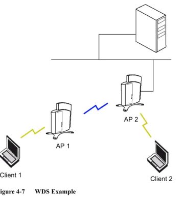
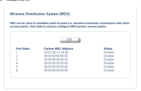
Wireless Distribution System (WDS) . . . 46
Wireless (802.11b/g) . . . 48
Ethernet . . . 49
Management . . . 50
Passwords . . . 50
IP Access Table . . . 50
Services . . . 51
Filtering . . . 52
Ethernet Protocol . . . 52
Static MAC . . . 53
Static MAC Filter Examples . . . 54
Advanced. . . 55
TCP/UDP Port . . . 56
Adding TCP/UDP Port Filters . . . 56
Editing TCP/UDP Port Filters . . . 56
Alarms . . . 57
Groups . . . 57
Severity Levels . . . 59
Syslog . . . 60
Setting Syslog Event Notifications . . . 60
Configuring Syslog Event Notifications. . . 61
Bridge . . . 61
Spanning Tree . . . 61
Storm Threshold . . . 62
Intra BSS . . . 62
Packet Forwarding. . . 62
Configuring Interfaces for Packet Forwarding . . . 62
Security . . . 63
Authentication and Encryption Modes . . . 63
WEP Encryption . . . 63
802.1x Authentication . . . 63
Wi-Fi Protected Access (WPA) . . . 65
Configuring Security Settings . . . 65
MAC Access . . . 68
RADIUS . . . . 69
MAC Access Control Via RADIUS Authentication . . . 70
RADIUS Authentication with 802.1x . . . 71
RADIUS Accounting . . . 72
Session Length. . . 72
Configuring RADIUS Accounting . . . 72
VLAN/SSID . . . 73
VLAN Overview . . . 73
VLAN Workgroups and Traffic Management . . . 75
Traffic Management . . . 75
Typical User VLAN Configurations . . . 75
Configure Multiple VLAN/SSID Pairs . . . 75
Typical VLAN Management Configurations . . . 76
Control Access to the AP . . . 76
Provide Access to a Wireless Host in the Same Workgroup . . . 76
Disable VLAN Management . . . 77
5 Monitor Information . . . .78
Logging into the HTTP Interface . . . 78
Version . . . 80
ICMP . . . 81
IP/ARP Table . . . 81
Learn Table . . . . 82
RADIUS . . . . 83
Interfaces . . . 84
Link Test (802.11b APs Only) . . . 85
6 Commands . . . .87
Logging into the HTTP Interface . . . 87
Download . . . . 89
Upload . . . 89
Reboot . . . 90
Reset . . . 91
Help Link . . . 91
7 Troubleshooting . . . .92
Troubleshooting Concepts . . . 92
Symptoms and Solutions . . . 93
Connectivity Issues . . . 93
AP Unit Will Not Boot - No LED Activity . . . 93
Serial Link Does Not Work . . . 93
Ethernet Link Does Not Work . . . 93
Basic Software Setup and Configuration Problems. . . 93
Lost AP, Telnet, or SNMP Password. . . 93
Client Computer Cannot Connect. . . 93
AP Has Incorrect IP Address . . . 93
HTTP (browser) or Telnet Interface Does Not Work . . . 94
HTML Help Files Do Not Appear . . . 94
Telnet CLI Does Not Work . . . 94
TFTP Server Does Not Work . . . 94
Client Connection Problems . . . 95
Client Software Finds No Connection. . . 95
Client PC Card Does Not Work . . . 95
Intermittent Loss of Connection . . . 95
Client Does Not Receive an IP Address - Cannot Connect to Internet . . . 95
VLAN Operation Issues . . . 95
Verifying Proper Operation of the VLAN Feature . . . 95
VLAN Workgroups . . . 95
Active Ethernet (AE) . . . 96
The AP Does Not Work . . . 96
There Is No Data Link. . . 96
Recovery Procedures . . . 96
Reset to Factory Default Procedure . . . 97
Forced Reload Procedure . . . 97
Download a New Image Using ScanTool . . . 98
Download a New Image Using the Bootloader CLI . . . 99
Setting IP Address using Serial Port . . . 100
Hardware and Software Requirements. . . 100
Attaching the Serial Port Cable. . . 100
Initializing the IP Address using CLI . . . 100
Related Applications . . . 102
RADIUS Authentication Server . . . 102
TFTP Server . . . 102
A Command Line Interface (CLI) . . . .103
General Notes . . . 103
Prerequisite Skills and Knowledge . . . 103
Notation Conventions . . . 103
Important Terminology . . . 103
Navigation and Special Keys . . . 104
CLI Error Messages. . . 104
Command Line Interface (CLI) Variations . . . 104
Bootloader CLI. . . 105
CLI Command Types . . . 106
Operational CLI Commands . . . 106
? (List Commands) . . . 106
done, exit, quit . . . 108
download . . . 108
help. . . 108
history . . . 109
passwd . . . 109
reboot . . . 109
search. . . 109
upload. . . .110
Parameter Control Commands . . . .110
“show” CLI Command. . . .110
“set” CLI Command . . . .110
Configuring Objects that Require Reboot . . . .111
“set” and “show” Command Examples . . . .111
Using Tables & User Strings . . . 113
Working with Tables. . . .113
Configuring the AP using CLI commands . . . 114
Log into the AP using HyperTerminal . . . .114
Log into the AP using Telnet . . . .114
Set Basic Configuration Parameters using CLI Commands . . . 115
Set System Name, Location and Contact Information . . . .115
Set Static IP Address for the AP. . . .115
Change Passwords . . . .115
Set Network Names for the Wireless Interface. . . .116
Set WEP Encryption for the Wireless Interface . . . .116
Download an AP Configuration File from your TFTP Server . . . .117
Backup your AP Configuration File. . . .117
Other Network Settings . . . 117
Configure the AP as a DHCP Server . . . .118
Configure the DNS Client . . . .118
Maintain Client Connections using Link Integrity . . . .118
Change your Wireless Interface Settings . . . .119
Set Ethernet Speed and Transmission Mode . . . 120
Set Interface Management Services . . . 120
Configure Syslog . . . 121
Configure Intra BSS . . . 121
Configure MAC Access Control . . . 121
Configure Authentication Mode . . . 121
Set RADIUS Parameters . . . 122
Set VLAN/SSID Parameters. . . 123
CLI Monitoring Parameters . . . 124
Parameter Tables . . . 124
System Parameters . . . 125
Inventory Management Information . . . 125
Network Parameters . . . 126
IP Configuration Parameters . . . 126
DHCP Server Parameters . . . 126
Link Integrity Parameters . . . 127
Interface Parameters . . . 128
Wireless Interface Parameters . . . 128
Ethernet Interface Parameters . . . 131
Management Parameters . . . 131
SNMP Parameters . . . 131
HTTP (web browser) Parameters . . . 131
Telnet Parameters . . . 132
TFTP Server Parameters . . . 132
IP Access Table Parameters . . . 133
Filtering Parameters . . . 133
Ethernet Protocol Filtering Parameters . . . 133
Static MAC Address Filter Table . . . 134
Proxy ARP Parameters . . . 134
IP ARP Filtering Parameters . . . 134
Broadcast Filtering Table . . . 134
TCP/UDP Port Filtering . . . 135
Alarms Parameters . . . 136
SNMP Table Host Table Parameters . . . 136
Syslog Parameters . . . 136
Bridge Parameters. . . 137
Spanning Tree Parameters. . . 137
Storm Threshold Parameters . . . 137
Intra BSS Subscriber Blocking . . . 138
Packet Forwarding Parameters . . . 138
Security Parameters . . . 138
Wireless Interface Security Parameters . . . 139
MAC Access Control Parameter. . . 139
RADIUS Parameters . . . 140
Primary and Backup RADIUS Server Table Parameters . . . 140
VLAN/SSID Parameters . . . 141
VLAN ID Table . . . 141
Other Parameters . . . 142
IAPP Parameters . . . 142
SpectraLink VoIP Parameters (802.11b Only) . . . 142
B ASCII Character Chart . . . .143
C Specifications . . . .144
Software Features . . . 144
Management Functions . . . 144
Advanced Bridging Functions . . . 144
Medium Access Control (MAC) Functions . . . 145
Security Functions . . . 145
Network Functions . . . 145
Advanced Wireless Functions . . . 146
Hardware Specifications . . . 146
Physical Specifications . . . 146
Electrical Specifications . . . 146
Ethernet Interface . . . 147
Serial Port Interface . . . 147
Active Ethernet Interface . . . 147
HTTP Interface . . . 147
Radio Specifications . . . 147
802.11a Channel Frequencies. . . 147
802.11b Channel Frequencies. . . 148
802.11g Channel Frequencies. . . 149
Wireless Communication Range . . . 150
1
Introduction
• Document Conventions
• Introduction to Wireless Networking
• IEEE 802.11 Specifications
• Management and Monitoring Capabilities
Document Conventions
• The term, AP, refers to an Access Point.• The term, 802.11, is used to describe features that apply to the 802.11a, 802.11b, and 802.11g wireless standards. • A Single-radio AP is an Access Point that supports one IEEE radio standard. The AP-600 is a Single-radio AP. • A Dual-radio AP is an Access Point that includes two radios; it can support one or two IEEE radio standards
(depending on the type of radios installed). The AP-2000 is a Dual-radio AP. • An 802.11a AP is an Access Point that supports the IEEE 802.11a standard. • An 802.11b AP is an Access Point that supports the IEEE 802.11b standard. • An 802.11b/g AP is an Access Point that supports the IEEE 802.11g standard.
• Blue underlined text indicates a link to a topic or Web address. If you are viewing this documentation on your computer, click the blue text to jump to the linked item.
NOTE
A Note indicates important information that helps you make better use of your computer.
CAUTION
!
A Caution indicates either potential damage to hardware or loss of data and tells you how to avoid the problem.
Introduction to Wireless Networking
An AP extends the capability of an existing Ethernet network to devices on a wireless network. Wireless devices can connect to a single Access Point, or they can move between multiple Access Points located within the same vicinity. As wireless clients move from one coverage cell to another, they maintain network connectivity.
To determine the best location for an Access Point, Proxim recommends conducting a Site Survey before placing the device in its final location. For information about how to conduct a Site Survey, contact your local reseller.
Before an Access Point can be configured for your specific networking requirements, it must first be initialized. See
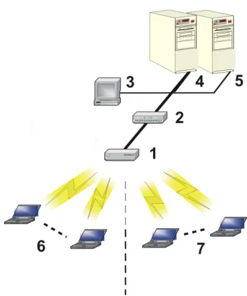
Figure 1-1 Typical wireless network access infrastructure
Once initialized, the network administrator can configure each unit according to the network’s requirements. The AP functions as a wireless network access point to data networks. An AP network provides:
• Seamless client roaming • Easy installation and operation • Over-the-air encryption of data • High speed network links
Guidelines for Roaming
• An AP can only communicate with client devices that support its wireless standard. For example, an 802.11a client cannot communicate with an 802.11b AP and an 802.11b client cannot communicate with an 802.11a AP. However, both 802.11b and 802.11g clients can communicate with an 802.11b/g AP.
• All Access Points must have the same Network Name to support client roaming.
• All workstations with an 802.11 client adapter installed must use either a Network Name of “any” or the same Network Name as the Access Points that they will roam between. If an AP has Closed System enabled, a client must have the same Network Name as the Access Point to communicate (see Interfaces).
• All Access Points and clients must have the same security settings to communicate.
• The Access Points’ cells must overlap to ensure that there are no gaps in coverage and to ensure that the roaming client will always have a connection available.
• The coverage area of an 802.11b or 802.11b/g AP is larger than the coverage area of an 802.11a AP. The 802.11b and 802.11b/g APs operate in the 2.4 GHz frequency band; the 802.11a AP operates in the 5 GHz band. Products that operate in the 2.4 GHz band offer greater range than products that operate in the 5 GHz band.
• An 802.11a or 802.11b/g AP operates at faster data rates than the 802.11b AP. 802.11a and 802.11g products operate at speeds of up to 54 Mbits/sec; 802.11b products operate at speeds of up to 11 Mbits/sec.
• All Access Points in the same vicinity should use a unique, independent Channel. By default, the AP automatically scans for available Channels during boot-up but you can also set the Channel manually (see Interfaces for details). • Access Points that use the same Channel should be installed as far away from each other as possible to reduce
IEEE 802.11 Specifications
In 1997, the Institute of Electrical and Electronics Engineers (IEEE) adopted the 802.11 standard for wireless devices operating in the 2.4 GHz frequency band. This standard includes provisions for three radio technologies: direct sequence spread spectrum, frequency hopping spread spectrum, and infrared. Devices that comply with the 802.11 standard operate at a data rate of either 1 or 2 Megabits per second (Mbits/sec).
In 1999, the IEEE modified the 802.11 standard to support direct sequence devices that can operate at speeds of up to 11 Mbits/sec. The IEEE ratified this standard as 802.11b. 802.11b devices are backwards compatible with 2.4 GHz 802.11 direct sequence devices (that operate at 1 or 2 Mbits/sec). Available Frequency Channels vary by regulatory domain and/or country. See 802.11b Channel Frequencies for details.
Also in 1999, the IEEE modified the 802.11 standard to support devices operating in the 5 GHz frequency band. This standard is referred to as 802.11a. 802.11a devices are not compatible with 2.4 GHz 802.11 or 802.11b devices. 802.11a radios use a radio technology called Orthogonal Frequency Division Multiplexing (OFDM) to achieve data rates of up to 54 Mbits/sec. Available Frequency Channels vary by regulatory domain and/or country. See 802.11a Channel Frequencies for details.
In 2003, the IEEE introduced the 802.11g standard. 802.11g devices operate in the 2.4 GHz frequency band using OFDM to achieve data rates of up to 54 Mbits/sec. In addition, 802.11g devices are backwards compatible with 802.11b devices. Available Frequency Channels vary by regulatory domain and/or country. See 802.11g Channel Frequencies for details.
Management and Monitoring Capabilities
There are several management and monitoring interfaces available to the network administrator to configure and manage an AP on the network:
• HTTP Interface
• Command Line Interface
• SNMP Management
HTTP Interface
The HTTP Interface (Web browser Interface) provides easy access to configuration settings and network statistics from any computer on the network. You can access the HTTP Interface over your LAN (switch, hub, etc.), over the Internet, or with a “crossover” Ethernet cable connected directly to your computer’s Ethernet Port.
Command Line Interface
The Command Line Interface (CLI) is a text-based configuration utility that supports a set of keyboard commands and parameters to configure and manage an AP.
Users enter Command Statements, composed of CLI Commands and their associated parameters. Statements may be issued from the keyboard for real time control, or from scripts that automate configuration.
For example, when downloading a file, administrators enter the download CLI Command along with IP Address, file name, and file type parameters.
You access the CLI over a HyperTerminal serial connection or via Telnet. During initial configuration, you can use the CLI over a serial port connection to configure an Access Point’s IP address. When accessing the CLI via Telnet, you can communicate with the Access Point from over your LAN (switch, hub, etc.), from over the Internet, or with a “crossover” Ethernet cable connected directly to your computer’s Ethernet Port.
SNMP Management
In addition to the HTTP and the CLI interfaces, you can also manage and configure an AP using the Simple Network Management Protocol (SNMP). Note that this requires an SNMP manager program, like HP Openview or Castlerock’s SNMPc.
The AP supports several Management Information Base (MIB) files that describe the parameters that can be viewed and/or configured over SNMP:
– MIB-II (RFC 1213) – Bridge MIB (RFC 1493) – Ethernet-like MIB (RFC 1643) – 802.11 MIB
– ORiNOCO Enterprise MIB
Proxim provides these MIB files on the CD included with each Access Point. You need to compile one or more of the above MIBs into your SNMP program’s database before you can manage an Access Point using SNMP. Refer to the documentation that came with your SNMP manager for instructions on how to compile MIBs.
The Enterprise MIB defines the read and read-write objects that can be viewed or configured using SNMP. These objects correspond to most of the settings and statistics that are available with the other management interfaces. Refer to the Enterprise MIB for more information; the MIB can be opened with any text editor, such as Microsoft Word, Notepad, or WordPad.
NOTE
The remainder of this guide describes how to configure an AP using the HTTP Web interface or the CLI interface. For information on how to manage devices using SNMP, refer to the documentation that came with your SNMP program. Also, refer to the MIB files for information on the parameters available via SNMP.
2
Getting Started
• Prerequisites
• Product Package
• System Requirements
• Hardware Installation
• Initialization
• Download the Latest Software
• Additional Hardware Features
Prerequisites
Before installing an AP, you need to gather certain network information. The following section identifies the information you need.
Network Name (SSID of the wireless cards) You must assign the Access Point a Network Name before wireless users can
communicate with it. The clients also need the same Network Name. This is not the same as the System Name, which applies only to the Access Point. The network administrator typically provides the Network Name.
AP’s IP Address If you do not have a DHCP server on your network, then you need to assign the Access Point an IP address that is valid on your network.
HTTP Password Each Access Point requires a read/write password to access the web interface. The default password is “public”.
CLI Password Each Access Point requires a read/write password to access the CLI interface. The default password is “public”.
SNMP Read Password Each Access Point requires a password to allow get requests from an SNMP manager. The default password is “public”.
SNMP Read-Write Password Each Access Point requires a password to allow get and set requests from an SNMP manager. The default password is “public”.
Security Settings You need to determine what security features you will enable on the Access Point. Authentication Method A primary authentication server may be configured; a backup authentication server is
optional. The network administrator typically provides this information.
Authentication Server Shared Secret This is a password shared between the Access Point and the RADIUS authentication server (so both passwords must be the same), and is typically provided by the network administrator.
Authentication Server Authentication Port This is a port number (default is 1812) and is typically provided by the network administrator.
Client IP Address Pool Allocation Scheme The Access Point can automatically provide IP addresses to clients as they sign on. The network administrator typically provides the IP Pool range.
Product Package
Each Single-radio AP comes with the following:
• One metal base for ceiling or desktop mounting (includes two screws) • Mounting hardware
– Four 3.5 mm x 40 mm screws – Four 6 mm x 35 mm plugs • One power supply
• One Installation CD-ROM that contains the following: – Software Installation Wizard
– ScanTool
– Solarwinds TFTP software – HTML Help
– this user’s guide in PDF format • One Access Point Quick Start Guide
If any of these items are missing or damaged, please contact your reseller or Technical Support (see Technical Support for contact information).
MiniPCI Upgrade Kits
Single-radio APs can be fitted with different radio types. MiniPCI upgrade kits are available for 802.11a/b/g and 802.11b/g wireless cards. Each kit is composed of a single miniPCI board with an integral antenna attached. The type of radio is indicated on the label on the antenna and instructions on how to open your AP to replace the radio are provided with the kit.
System Requirements
To begin using an AP, you must have the following minimum requirements: • A 10Base-T Ethernet or 100Base-TX Fast Ethernet switch or hub • At least one of the following IEEE 802.11-compliant devices:
– An 802.11a client device if you have an 802.11a AP
– An 802.11b or 802.11b/g client device if you have an 802.11b AP – An 802.11b/g client device if you have an 802.11b/g AP
• A computer that is connected to the same IP network as the AP and has one of the following Web browsers installed:
– Microsoft Internet Explorer 6 with Service Pack 1 or later – Netscape 6.1 or later
Hardware Installation
Follow these steps to install a Single-radio AP:
1. Unpack the Access Point and accessories from the shipping box.
2. If you intend to install the unit free-standing or if you intend to mount it to the ceiling, use a Phillips screwdriver to attach the metal base to the underside of the unit. The metal base and screws are provided. See Mounting Options
for additional information.
Figure 2-1 Attach the Metal Base
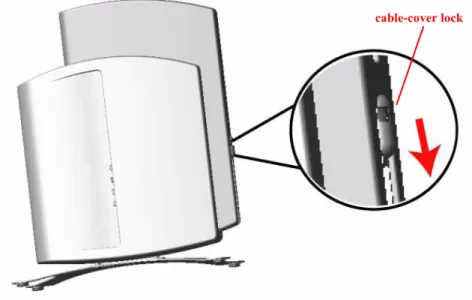
3. Press down on the cable-cover lock located in the front-center of the unit to release the cable cover.
Figure 2-2 Unlock the Cable Cover 4. Remove the cable cover from the unit.
Figure 2-3 Remove Cable Cover
5. Remove the front cover (the side with the LED indicators) from the unit.
Figure 2-4 Remove the Front Cover 6. Remove the back cover from the unit.
Figure 2-5 Remove the Back Cover
7. Connect one end of an Ethernet cable to the Access Point’s Ethernet port. The other end of the cable should not be connected to another device until after the installation is complete.
• Use a straight-through Ethernet cable if you intend to connect the Access Point to a hub, switch, patch panel, or Active Ethernet power injector.
• Use a cross-over Ethernet cable if you intend to connect the Access Point to a single computer.
8. If you are not using Active Ethernet (or you want to connect the Access Point to Active Ethernet and AC power simultaneously), attach the AC power cable to the Access Point’s power port.
Figure 2-6 Attach Ethernet Cable and Power Cable
Ethernet Cable Power Cable
NOTE
Once attached, the power cable locks into place. To disconnect the power cable, slide back the black plastic fitting and gently pull the cable from the connector.
9. Connect the free end of the Ethernet cable to a hub, switch, patch panel, Active Ethernet power injector, or an Ethernet port on a computer.
10. If using AC power, connect the power cord to a power source (such as a wall outlet) to turn on the unit. 11. Configure and test the unit. See Initialization for details.
12. Download the latest software to the unit, if necessary. See Download the Latest Software for details. 13. Place the unit in the final installation location. See Mounting Options for mounting options and instructions.
NOTE
Proxim recommends that you perform a Site Survey prior to determine the installation location for your AP units. For information about how to conduct a Site Survey, contact your local reseller.
14. Replace the back cover, front cover, and cable cover. Be careful to avoid trapping the power and Ethernet cables when replacing the cable cover.
Figure 2-7 Assembled Unit
15. If desired, you can attach a Kensington lock to secure the cable cover into place. This will protect the unit from unauthorized tampering. See Kensington Security Slot for details.
Initialization
Proxim provides two tools to simplify the initialization and configuration of an AP: • ScanTool
• Setup Wizard
ScanTool is included on the Installation CD; the Setup Wizard launches automatically the first time you access the HTTP interface.
NOTE
These initialization instructions describe how to configure an AP over an Ethernet connection using ScanTool and the HTTP interface. If you want to configure the unit over the serial port, see Setting IP Address using Serial Port for information on how to access the CLI over a serial connection and Command Line Interface (CLI) for a list of supported commands.
ScanTool
ScanTool is a software utility that is included on the installation CD-ROM. The tool automatically detects the Access Points installed on your network, regardless of IP address, and lets you configure each unit’s IP settings. In addition, you can use ScanTool to download new software to an AP that does not have a valid software image installed (see Client Connection Problems).
To access the HTTP interface and configure the AP, the AP must be assigned an IP address that is valid on its Ethernet network. By default, the AP is configured to obtain an IP address automatically from a network Dynamic Host Configuration Protocol (DHCP) server during boot-up. If your network contains a DHCP server, you can run ScanTool to find out what IP address the AP has been assigned. If your network does not contain a DHCP server, the
Access Point’s IP address defaults to 169.254.128.132. In this case, you can use ScanTool to assign the AP a static IP address that is valid on your network.
ScanTool Instructions
Follow these steps to install ScanTool, initialize the Access Point, and perform initial configuration:
1. Locate the unit’s Ethernet MAC address and write it down for future reference. The MAC address is printed on the product label. Each unit has a unique MAC address, which is assigned at the factory.
2. Confirm that the AP is connected to the same LAN subnet as the computer that you will use to configure the AP. 3. Power up, reboot, or reset the AP.
– Result: The unit requests an IP Address from the network DHCP server.
4. Insert the Installation CD into the CD-ROM drive of the computer that you will use to configure the AP. – Result: The installation program will launch automatically.
5. Follow the on-screen instructions to install the Access Point software and documentation.
NOTE
The ORiNOCO Installation program supports the following operating systems: • Windows 98SE
• Windows 2000 • Windows ME • Windows XP
6. After the software has been installed, double-click the ScanTool icon on the Windows desktop to launch the program (if the program is not already running).
– Result: ScanTool scans the subnet and displays all detected Access Points. The ScanTool’s Scan List screen appears, as shown in the following example.
NOTE
If your computer has more than one network adapter installed, you will be prompted to select the adapter that you want ScanTool to use before the Scan List appears. If prompted, select an adapter and click OK. You can change your adapter setting at any time by clicking the Select Adapter button on the Scan List screen. Note that the ScanTool Network Adapter Selection screen will not appear if your computer only has one network adapter installed.
Figure 2-8 Scan List
7. Locate the MAC address of the AP you want to initialize within the Scan List.
NOTE
If your Access Point does not show up in the Scan List, click the Rescan button to update the display. If the unit still does not appear in the list, see Troubleshooting for suggestions. Note that after rebooting an Access Point, it may take up to five minutes for the unit to appear in the Scan List.
8. Do one of the following:
• If the AP has been assigned an IP address by a DHCP server on the network, write down the IP address and click Cancel to close ScanTool. Proceed to Setup Wizard for information on how to access the HTTP interface using this IP address.
• If the AP has not been assigned an IP address (in other words, the unit is using its default IP address, 169.254.128.132), follow these steps to assign it a static IP address that is valid on your network: 1. Highlight the entry for the AP you want to configure.
2. Click the Change button.
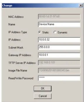
— Result: the Change screen appears.
3. Set IP Address Type to Static.
4. Enter a static IP Address for the AP in the field provided. You must assign the unit a unique address that is valid on your IP subnet. Contact your network administrator if you need assistance selecting an IP address for the unit.
5. Enter your network’s Subnet Mask in the field provided. 6. Enter your network’s Gateway IP Address in the field provided.
7. Enter the SNMP Read/Write password in the Read/Write Password field (for new units, the default SNMP Read/Write password is “public”).
NOTE
The TFTP Server IP Address and Image File Name fields are only available if ScanTool detects that the AP does not have a valid software image installed. See Client Connection Problems.
8. Click OK to save your changes.
— Result: The Access Point will reboot automatically and any changes you made will take effect. 9. When prompted, click OK a second time to return to the Scan List screen.
10. Click Cancel to close the ScanTool.
11. Proceed to Setup Wizard for information on how to access the HTTP interface.
Setup Wizard
The first time you connect to an AP’s HTTP interface, the Setup Wizard launches automatically. The Setup Wizard provides step-by-step instructions for how to configure the Access Point’s basic operating parameter, such as Network Name, IP parameters, system parameters, and management passwords.
Setup Wizard Instructions
Follow these steps to access the Access Point’s HTTP interface and launch the Setup Wizard: 1. Open a Web browser on a network computer.
– The HTTP interface supports the following Web browser: • Microsoft Internet Explorer 6 with Service Pack 1 or later • Netscape 6.1 or later
2. If necessary, disable the browser’s Internet proxy settings. For Internet Explorer users, follow these steps: – Select Tools > Internet Options....
– Click the Connections tab. – Click LAN Settings....
– If necessary, remove the check mark from the Use a proxy server box. – Click OK twice to save your changes and return to Internet Explorer.
3. Enter the Access Point’s IP address in the browser’s Address field and press Enter.
– This is either the dynamic IP address assigned by a network DHCP server or the static IP address you manually configured. See ScanTool for information on how to determine the unit’s IP address and manually configure a new IP address, if necessary.
– Result: The Enter Network Password screen appears.
4. Enter the HTTP password in the Password field. Leave the User Name field blank. For new units, the default HTTP password is “public”.
Figure 2-10 Enter Network Password
Figure 2-11 Setup Wizard
5. Click Setup Wizard to begin. If you want to configure the AP without using the Setup Wizard, click Exit and see
Advanced Configuration.
The Setup Wizard supports the following navigation options:
• Save & Next Button: Each Setup Wizard screen has a Save & Next button. Click this button to submit any changes you made to the unit’s parameters and continue to the next page. The instructions below describe how to navigate the Setup Wizard using the Save & Next buttons.
• Navigation Panel: The Setup Wizard provides a navigation panel on the left-hand side of the screen. Click the link that corresponds to the parameters you want to configure to be taken to that particular configuration screen. Note that clicking a link in the navigation panel will not submit any changes you made to the unit’s configuration on the current page.
• Exit: The navigation panel also includes an Exit option. Click this link to close the Setup Wizard at any time.
CAUTION
!
If you exit from the Setup Wizard, any changes you submitted (by clicking the Save & Next button) up to that point will be saved to the unit but will not take effect until it is rebooted.
6. Configure the System Configuration settings and click Save & Next. See System for more information. 7. Configure the Access Point’s Basic IP address settings, if necessary, and click Save & Next. See Basic IP
8. Assign the AP new passwords to prevent unauthorized access and click Save & Next. Each management interface has its own password:
— SNMP Read Password — SNMP Read-Write Password — CLI Password
— HTTP (Web) Password
By default, each of these passwords is set to “public”. See Passwords for more information. 9. Configure the basic wireless interface settings and click Save & Next.
• The following options are available for an 802.11a AP:
— Network Name (SSID): Enter a Network Name (between 1 and 32 characters long) for the wireless network. You must configure each wireless client to use this name as well.
— Auto Channel Select: By default, the AP scans the area for other Access Points and selects the best available communication channel, either a free channel (if available) or the channel with the least amount of interference. Remove the check mark to disable this option. Note that you cannot disable Auto Channel Select for 802.11a products in Europe (see Dynamic Frequency Selection (DFS) for details).
— Frequency Channel: When Auto Channel Select is enabled, this field is read-only and displays the Access Point’s current operating channel. When Auto Channel Select is disabled, you can specify the Access Point’s channel. If you decide to manually set the unit’s channel, ensure that nearby devices do not use the same frequency. Available Channels vary based on regulatory domain. See 802.11a Channel Frequencies. Note that you cannot manually set the channel for 802.11a products in Europe (see
Dynamic Frequency Selection (DFS) for details).
— Transmit Rate: Use the drop-down menu to select a specific transmit rate for the AP. Choose between 6, 9, 12, 18, 24, 36, 48, 54 Mbits/s, and Auto Fallback. The Auto Fallback feature allows the AP to select the best transmit rate based on the cell size.
— WEP Encryption: Place a check mark in the box provided to enable WEP encryption. See WEP Encryption for more information.
— Set Encryption Key 1: If you enabled Encryption, configure an Encryption Key. This key is used to encrypt and decrypt data between the AP and its wireless clients. Enter the number of characters that correspond to the desired key size, as described below:
— Enter 10 hexadecimal characters (0-9 and A-F) or 5 ASCII characters (see ASCII Character Chart) to use 64-bit encryption.
— Enter 26 hexadecimal characters or 13 ASCII characters to use 128-bit encryption. — Enter 32 hexadecimal characters or 16 ASCII characters to use 152-bit encryption. • The following options are available for an 802.11b AP:
— Network Name (SSID): Enter a Network Name (between 1 and 32 characters long) for the wireless network. You must configure each wireless client to use this name as well.
— Auto Channel Select: By default, the AP scans the area for other Access Points and selects the best available communication channel, either a free channel (if available) or the channel with the least amount of interference. Remove the check mark to disable this option. If you are setting up a Wireless Distribution System (WDS), it must be disabled. See Wireless Distribution System (WDS) for more information. — Frequency Channel: When Auto Channel Select is enabled, this field is read-only and displays the
Access Point’s current operating channel. When Auto Channel Select is disabled, you can specify the Access Point’s operating channel. If you decide to manually set the unit’s channel, ensure that nearby devices do not use the same frequency (unless you are setting up a WDS). Available Channels vary based on regulatory domain. See 802.11b Channel Frequencies.
— Distance Between APs: Set to Large, Medium, Small, Microcell, or Minicell depending on the site survey for your system. The distance value is related to the Multicast Rate (described next). In general, a larger distance between APs means that your clients operate a slower data rates (on average). See
— Multicast Rate: Sets the rate at which Multicast messages are sent. This value is related to the Distance Between APs parameter (described previously). The table below displays the possible Multicast Rates based on the Distance between APs. See Multicast Rate for more information.
— WEP Encryption: Place a check mark in the box provided to enable WEP encryption. See WEP Encryption for more information.
— Set Encryption Key 1: If you enabled Encryption, configure an Encryption Key. This key is used to encrypt and decrypt data between the AP and its wireless clients. Enter the number of characters that correspond to the desired key size, as described below:
— Enter 10 hexadecimal characters (0-9 and A-F) or 5 ASCII characters (see ASCII Character Chart) to use 64-bit encryption.
— Enter 26 hexadecimal characters (0-9 and A-F) or 13 ASCII characters to use 128-bit encryption. • The following options are available for an 802.11b/g AP:
— Operational Mode: An 802.11b/g wireless interface can be configured to operate in the following modes: — 802.11b mode only
— 802.11g mode only — 802.11g-wifi mode — 802.11b/g mode (default)
— Network Name (SSID): Enter a Network Name (between 1 and 32 characters long) for the wireless network. You must configure each wireless client to use this name as well.
— Auto Channel Select: By default, the AP scans the area for other Access Points and selects the best available communication channel, either a free channel (if available) or the channel with the least amount of interference. Remove the check mark to disable this option.
— Frequency Channel: When Auto Channel Select is enabled, this field is read-only and displays the Access Point’s current operating channel. When Auto Channel Select is disabled, you can specify the Access Point’s channel. If you decide to manually set the unit’s channel, ensure that nearby devices do not use the same frequency. Available Channels vary based on regulatory domain. See 802.11g Channel Frequencies.
— Transmit Rate: Select a specific transmit rate for the AP. The values available depend on the Operational Mode. Auto Fallback is the default setting; it allows the AP to select the best transmit rate based on the cell size.
— For 802.11b only -- Auto Fallback, 1, 2, 5.5, 11 Mbits/sec
— For 802.11g only -- Auto Fallback, 6, 9, 12, 18, 24, 36, 48, 54 Mbits/sec
— For 802.11b/g and 802.11g-wifi-- Auto Fallback, 1, 2, 5.5, 6, 9, 11, 12, 18, 24, 36, 48, 54 Mbits/sec — WEP Encryption: Place a check mark in the box provided to enable WEP encryption. See WEP
Encryption for more information.
— Set Encryption Key 1: If you enabled Encryption, configure an Encryption Key. This key is used to encrypt and decrypt data between the AP and its wireless clients. Enter the number of characters that correspond to the desired key size, as described below:
— Enter 10 hexadecimal characters (0-9 and A-F) or 5 ASCII characters (see ASCII Character Chart) to use 64-bit encryption.
— Enter 26 hexadecimal characters or 13 ASCII characters to use 128-bit encryption. — Enter 32 hexadecimal characters or 16 ASCII characters to use 152-bit encryption.
NOTE
Additional advanced settings are available in the Wireless Interface Configuration screen. See Wireless (802.11a), Wireless (802.11b), or Wireless (802.11b/g) for details. See Security for more information on security features.
Distance between APs Multicast Rate
Large 1 and 2 Mbits/sec Medium 1, 2, and 5.5 Mbits/sec Small 1, 2, 5.5 and 11 Mbits/sec Minicell 1, 2, 5.5 and 11 Mbits/sec Microcell 1, 2, 5.5 and 11 Mbits/sec
10. Review the configuration summary. If you want to make any additional changes, use the navigation panel on the left-hand side of the screen to return to an earlier screen. After making a change, click Save & Next to save the change and proceed to the next screen.
11. When finished, click Reboot on the Summary screen to restart the AP and apply your changes.
Download the Latest Software
Proxim periodically releases updated software for the AP on its Web site at http://www.proxim.com. Proxim recommends that you check the Web site for the latest updates after you have installed and initialized the unit. Three types of files can be downloaded to the AP from a TFTP server:
— img (AP software image or kernel) — config (configuration file)
— bspBl (BSP/Bootloader firmware file)
Setup your TFTP Server
A Trivial File Transfer Protocol (TFTP) server allows you to transfer files across a network. You can upload files from the AP for backup or copying, and you can download the files for configuration and AP Image upgrades. The Solarwinds TFTP server software is located on the ORiNOCO AP Installation CD-ROM. You can also download the latest TFTP software from Solarwind’s Web site at http://www.solarwinds.net.
If a TFTP server is not configured and running, you will not be able to download and upload images and configuration files to/from the AP. Remember that the TFTP server does not have to be local as long as you have a valid TFTP IP address. Also, a TFTP server does not have to be running for the AP to perform tasks that do not involve file transfers. After the TFTP server is installed:
• Check to see that TFTP is configured to point to the directory containing the AP Image.
• Make sure you have the proper TFTP server IP address, the proper AP Image file name, and that the TFTP server is operational.
• Make sure the TFTP server is configured to both Transmit and Receive files, with no automatic shutdown or time-out.
Download Updates from your TFTP Server using the Web Interface
1. Download the latest software from http://www.proxim.com.2. Copy the latest software updates to your TFTP server.
3. In the Web Interface, click the Commands button and select the Download tab. 4. Enter the IP address of your TFTP server in the field provided.
5. Enter the File Name (including the file extension). Enter the full directory path and file name. If the file is located in the default TFTP directory, you need enter only the file name.
6. Select the File Type from the drop-down menu (use Img for software updates). 7. Select Download & Reboot from the File Operation drop-down menu. 8. Click OK.
9. The Access Point will reboot automatically when the download is complete.
Download Updates from your TFTP Server using the CLI Interface
1. Download the latest software from http://www.proxim.com.2. Copy the latest software updates to your TFTP server. 3. Open the CLI interface via Telnet or a serial connection. 4. Enter the CLI password when prompted.
5. Type set tftpfilename <file name> (include the file extension) and press Enter. 6. Type set tftpfiletype img and press Enter.
7. Type set tftpipaddr <IP address of your TFTP server> and press Enter.
9. Type download * and press Enter.
– Result: The download will begin. Be patient while the image is downloaded to the Access Point. 10. When the download is complete, type reboot 0 and press Enter.
NOTE
See Command Line Interface (CLI) for more information.
Additional Hardware Features
• Mounting Options
• Installing the AP in a Plenum
• Kensington Security Slot
• Active Ethernet
• LED Indicators
Mounting Options
There are three mounting options for the AP, described below.
Desktop Mount
This is the standard installation for the AP. See Hardware Installation for instructions.
Wall Mount
Follow these steps to mount the AP on a wall:
1. Identify the location where you intend to mount the unit.
NOTE
For best results, mount the unit vertically. In other words, the antenna should be pointing up or down but not sideways.
2. Unplug the Access Point’s power supply, if necessary.
3. Use a Phillips screwdriver to remove the metal base from the underside of the AP, if necessary.
4. Press down on the cable cover lock to release the cable cover. See Unlock the Cable Cover for an illustration. 5. Remove the cable cover from the unit. See Remove Cable Cover for an illustration.
6. Remove the front cover from the unit. See Remove the Front Cover for an illustration. 7. Remove the back cover from the unit. See Remove the Back Cover for an illustration.
8. Place the back cover on the mounting location and mark the center of the three mounting holes.
9. Remove the cover from the wall and drill a hole at each of the locations you marked above. Each hole should be wide enough to hold a mounting plug (which is 6 mm x 35 mm).
10. Insert a plug into each hole. The AP comes with four 6 mm x 35 mm plugs; you only need to use three of these when wall mounting the unit.
11. Insert a screw into each of the mounting holes molded into the back cover. The AP comes with four 3.5 mm x 40 mm pan-head screws; you only need to use three of these when wall mounting the unit.
12. Insert the screws into the wall plugs. Use a screwdriver to tighten the screws and attach the back cover to the wall. In the following example, the back cover is mounted upside down (the two holes are at the bottom).
Figure 2-12 Attach the Back Cover to the Wall
13. Attach Ethernet and power cables to the AP unit, if necessary.
14. Snap the unit into the back cover. In the following example, the unit is mounted upside down and its antenna is facing down.
15. Replace the front cover. 16. Replace the cable cover. 17. Turn on the AP.
Ceiling Mount
Follow these steps to mount the AP to a ceiling:
1. Unplug the Access Point’s power supply, if necessary.
2. Use a Phillips screwdriver to attach the metal base to the underside of the AP, if necessary. See Attach the Metal Base for an illustration.
3. Feed a mounting screw through each of the four rubber feet. The AP comes with four 3.5 mm x 40 mm pan-head screws.
4. Remove the screws from the rubber feet.
5. Turn the AP upside down position the base against the ceiling where you want to mount the unit. 6. Mark the center of the four mounting holes in the rubber feet.
7. Set the AP aside and drill a hole at each of the locations you marked above. Each hole should be wide enough to hold a mounting plug (which is 6 mm x 35 mm).
8. Insert a plug into each hole. The AP comes with four 6 mm x 35 mm plugs. 9. Insert the screws into the holes you made previously in the rubber feet.
10. Insert the screws into the wall plugs. Use a screwdriver to tighten the screws and attach the Access Point’s metal base to the ceiling.
Installing the AP in a Plenum
In an office building, plenum is the space between the structural ceiling and the tile ceiling that is provided to help air circulate. Many companies also use the plenum to house communication equipment and cables. However, these products and cables must comply with certain safety requirements, such as Underwriter Labs (UL) Standard 2043: “Standard for Fire Test for Heat and Visible Smoke Release for Discrete Products and Their Accessories Installed in Air-Handling Spaces”.
The AP has been certified under UL Standard 2043 and can be installed in the plenum only when the following conditions apply:
• The unit uses Active Ethernet (AE) to receive power over a plenum-rated Category 5 Ethernet cable (the power cable must not be connected to the unit).
• The unit’s plastic covers have been removed (this includes the cable cover, the front cover, and the back cover).
Kensington Security Slot
The AP enclosure includes a Kensington Security Slot for use with a Kensington locking mechanism. When properly installed, a Kensington lock can prevent unauthorized personnel from stealing the AP. In addition, the Kensington locks secures the cable cover in place, which prevents tampering with the Ethernet and power cables.
The Kensington Security Slot is shown in the illustrations below (the figure on the left shows the slot with the cable cover attached; the figure on the right shows the slot with the cable cover removed). See http://www.kensington.com
for information on Kensington security solutions.
Active Ethernet
An Active Ethernet-enabled AP is equipped with an 802.3af-compliant Active Ethernet module. Active Ethernet (AE) delivers both data and power to the access point over a single Ethernet cable. If you choose to use Active Ethernet, there is no difference in operation; the only difference is in the power source.
– The Active Ethernet (AE) integrated module receives ~48 VDC over a standard Category 5 Ethernet cable. – To use Active Ethernet, you must have an AE hub (also known as a power injector) connected to the network. – The cable length between the AE hub and the Access Point should not exceed 100 meters (approximately
325 feet).
– The AE hub is not a repeater and does not amplify the Ethernet data signal.
– If connected to an AE hub and an AC power simultaneously, the Access Point draws power from Active Ethernet.
– Maximum power supplied to an Access Point is 11 Watts; the unit typically draws approximately 10 Watts. Also see Hardware Specifications.
NOTE
The AP’s 802.3af-compliant Active Ethernet module is backwards compatible with all ORiNOCO Active Ethernet hubs that do not support the IEEE 802.3af standard.
LED Indicators
The AP has four LED indicators. The LEDs are identified in LED Indicators Illustrated and exhibit the following behavior:
Power Ethernet Link Ethernet Activity Wireless Activity Indication
Solid Green Green when link
exists Green flash with data activity Green flash with data activity Normal Operation
Solid Amber Solid Amber Solid Amber Solid Amber Rebooting/Power on Self Test (POST) Solid Green Solid Amber Solid Amber Solid Amber Reset to Factory Defaults command issued Solid Red Off Off Off SDRAM Test Failure
Blinking Red Blinking Red or Off Blinking Red Off Hardware Timer Test Failure Blinking Red Off Off Blinking Red Flash Test Failure Solid Red Blinking Red or Off Solid Red Off Ethernet Test Failure Solid Red Off Off Solid Red Wireless Test Failure Blinking Amber Blinking Amber or Off Blinking Amber or Off Off Missing or bad AP image
Solid Amber Solid Amber Solid Amber Solid Amber Missing or bad bootloader image (all LEDs remain solid amber)
n/a n/a n/a Red Wireless radio is not working properly n/a n/a Amber Amber Indicated interface in administrative down state
Figure 2-16 LED Indicators Illustrated
Related Topics
The Setup Wizard helps you configure the basic AP settings required to get the unit up and running. The AP supports many other configuration and management options. The remainder of this user guide describes these options in detail. – See Advanced Configuration for information on configuration options that are available within the Access Point’s
HTTP interface.
– See Monitor Information for information on the statistics displayed within the Access Point’s HTTP interface. – See Commands for information on the commands supported by the Access Point’s HTTP interface. – See Troubleshooting for troubleshooting suggestions.
– See Command Line Interface (CLI) for information on the CLI interface and for a list of CLI commands.
Power LED
Wireless Activity LED Ethernet Activity LED Ethernet Link LED
3
Status Information
• Logging into the HTTP Interface
• System Status
Logging into the HTTP Interface
Once the AP has a valid IP Address and an Ethernet connection, you may use your web browser to monitor the system status.
Follow these steps to monitor an AP’s operating statistics using the HTTP interface: 1. Open a Web browser on a network computer.
NOTE
The HTTP interface supports the following Web browser: • Microsoft Internet Explorer 6 with Service Pack 1 or later • Netscape 6.1 or later
2. If necessary, disable the Internet proxy settings. For Internet Explorer users, follow these steps: – Select Tools > Internet Options....
– Click the Connections tab. – Click LAN Settings....
– If necessary, remove the check mark from the Use a proxy server box. – Click OK twice to save your changes and return to Internet Explorer.
3. Enter the Access Point’s IP address in the browser’s Address field and press Enter. – Result: The Enter Network Password screen appears.
4. Enter the HTTP password in the Password field and click OK. Leave the User Name field blank. (By default, the HTTP password is “public”).
– Result: The System Status screen appears.
System Status
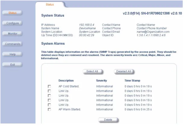
System Status is the first screen to appear each time you connect to the HTTP interface. You can also return to this screen by clicking the Status button.
Figure 3-2 System Status Screen
Each section of the System Status screen provides the following information:
– System Status: This area provides system level information, including the unit’s IP address and contact information. See System for information on these settings.
– System Alarms: System traps (if any) appear in this area. Each trap identifies a specific severity level: Critical, Major, Minor, and Informational. See Alarms for a list of possible alarms.
4
Advanced Configuration
• Configuring the AP Using the HTTP Interface
• System: Configure specific system information such as system name and contact information. • Network: Configure IP settings, DNS client, DHCP server, and Link Integrity.
• Interfaces: Configure the Access Point’s interfaces: Wireless and Ethernet.
• Management: Configure the Access Point’s management Passwords, IP Access Table, and Services. • Filtering: Configure Ethernet Protocol filters, Static MAC Address filters, Advanced filters, and Port filters. • Alarms: Configure the Alarm (SNMP Trap) Groups, the Alarm Host Table, and the Syslog features. • Bridge: Configure the Spanning Tree Protocol, Storm Threshold protection, Intra BSS traffic, and Packet
Forwarding.
• Security: Configure security features such as MAC Access Control, WPA, WEP Encryption, and 802.1x. • RADIUS: Configure RADIUS features such as RADIUS Access Control and Accounting.
• VLAN/SSID: Configure VLAN IDs and SSIDs.
Configuring the AP Using the HTTP Interface
Follow these steps to configure an Access Point’s operating settings using the HTTP interface: 1. Open a Web browser on a network computer.
NOTE
The HTTP interface supports the following Web browser: • Microsoft Internet Explorer 6 with Service Pack 1 or later • Netscape 6.1 or later
2. If necessary, disable the Internet proxy settings. For Internet Explorer users, follow these steps: – Select Tools > Internet Options....
– Click the Connections tab. – Click LAN Settings....
– If necessary, remove the check mark from the Use a proxy server box. – Click OK twice to save your changes and return to Internet Explorer.
3. Enter the Access Point’s IP address in the browser’s Address field and press Enter. – Result: The Enter Network Password screen appears.
4. Enter the HTTP password in the Password field and click OK. Leave the User Name field blank. (By default, the HTTP password is “public”).
Figure 4-1 Enter Network Password Screen
5. Click the Configure button located on the left-hand side of the screen.
Figure 4-2 Configure Main Screen
6. Click the tab that corresponds to the parameter you want to configure. For example, click Network to configure the Access Point’s TCP/IP settings. The parameters contained in each of the nine configuration categories are described later in this chapter.
7. Configure the Access Point’s parameters as necessary. After changing a configuration value, click OK to save the change.
System
You can configure and view the following parameters within the System Configuration screen: • Name: The name assigned to the AP.
• Location: The location where the AP is installed.
• Contact Name: The name of the person responsible for the AP. • Contact Email: The email address of the person responsible for the AP. • Contact Phone: The telephone number of the person responsible for the AP.
• Object ID: This is a read-only field that displays the Access Point’s MIB definition; this information is useful if you are managing the AP using SNMP.
• Ethernet MAC Address: This is a read-only field that displays the unique MAC (Media Access Control) address for the Access Point’s Ethernet interface. The MAC address is assigned at the factory.
• Descriptor: This is a read-only field that reports the Access Point’s name, serial number, current image software version, and current bootloader software version.
• Up Time: This is a read-only field that displays how long the Access Point has been running since its last reboot.
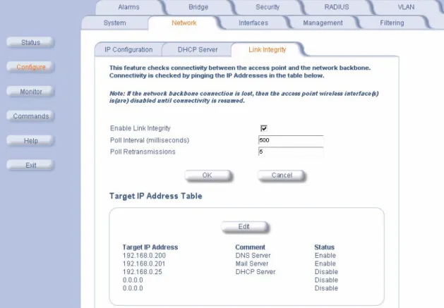
Network
The Network category contains three sub-categories. – IP Configuration
– DHCP Server
– Link Integrity
IP Configuration
You can configure and view the following parameters within the IP Configuration screen:
NOTE
You must reboot the Access Point in order for any changes to the Basic IP or DNS Client parameters take effect.
Basic IP Parameters
• IP Address Assignment Type: Set this parameter to Dynamic to configure the Access Point as a Dynamic Host Configuration Protocol (DHCP) client; the Access Point will obtain IP settings from a network DHCP server automatically during boot-up. If you do not have a DHCP server or if you want to manually configure the Access Point’s IP settings, set this parameter to Static.
• IP Address: The Access Point’s IP address. When IP Address Assignment Type is set to Dynamic, this field is read-only and reports the unit’s current IP address. The Access Point will default to 169.254.128.132 if it cannot obtain an address from a DHCP server.
• Subnet Mask: The Access Point’s subnet mask. When IP Address Assignment Type is set to Dynamic, this field is read-only and reports the unit’s current subnet mask. The subnet mask will default to 255.255.0.0 if the unit cannot obtain one from a DHCP server.
• Gateway IP Address: The IP address of the Access Point’s gateway. When IP Address Assignment Type is set to Dynamic, this field is read-only and reports the IP address of the unit’s gateway. The gateway IP address will default to 169.254.128.133 if the unit cannot obtain an address from a DHCP server.
DNS Client
If you prefer to use host names to identify network servers rather than IP addresses, you can configure the AP to act as a Domain Name Service (DNS) client. When this feature is enabled, the Access Point contacts the network’s DNS server to translate a host name to the appropriate network IP address. You can use this DNS Client functionality to identify RADIUS servers by host name. See RADIUS for details.
• Enable DNS Client: Place a check mark in the box provided to enable DNS client functionality. Note that this option must be enabled before you can configure the other DNS Client parameters.
• DNS Secondary Server IP Address: The IP address of a second DNS server on the network. The Access Point will attempt to contact the secondary server if the primary server is unavailable.
• DNS Client Default Domain Name: The default domain name for the Access Point’s network (for example, “proxim.com”). Contact your network administrator if you need assistance setting this parameter.
Advanced
• Default TTL (Time to Live): Time to Live (TTL) is a field in an IP packet that specifies how long in seconds the packet can remain active on the network. The Access Point uses the default TTL for packets it generates for which the transport layer protocol does not specify a TTL value. This parameter supports a range from 0 to 65535. By default, TTL is 64.
DHCP Server
If your network does not have a DHCP Server, you can configure the AP as a DHCP server to assign dynamic IP addresses to Ethernet nodes and wireless clients.
CAUTION
!
Make sure there are no other DHCP servers on the network and do not enable the DHCP server without checking with your network administrator first, as it could bring down the whole network. Also, the AP must be configured with a static IP address before enabling this feature.
When the DHCP Server functionality is enabled, you can create one or more IP address pools from which to assign addresses to network devices.