Bandwidth Optimization and Protection
for Wireless Backhaul
Tien Shiah
March 2009
Introduction
As multimedia applications become ubiquitous on mobile phones, service providers will need to dramatically increase the bandwidth of their backhaul networks. This poses a challenge, as transmission facilities are one of the largest contributors to a service provider’s operating costs. The need to mitigate these costs is driving the migration of backhaul connections onto more efficient packet-based networks.
This paper discusses the evolving wireless backhaul network, and an elegant method to optimize as well as protect the traffic flowing through it.
Evolution of Wireless Backhaul
Wireless mobile technologies include cellular as well as WiMAX1. Cellular networks are in the midst
of 3G deployments, with 4G equipment currently under development2. LTE networks3 will eventually
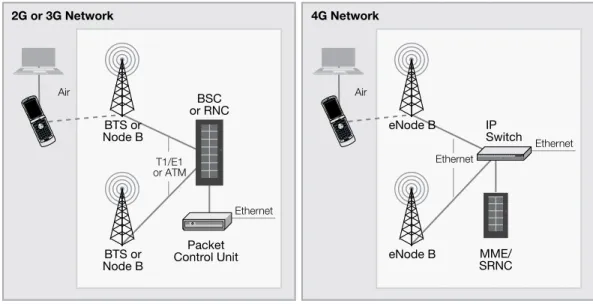
enable subscriber data download rates as high as 100 Mbps. WiMAX will also evolve into a 4G technology that competes with cellular. Its peak data rates will be around 70 Mbps. In order to offer subscribers such high data rates on user devices, the backhaul network needs to be upgraded. Wireless backhaul refers to either the connection from base stations to the network controller, or from the network controller to the mobile operator’s core network. A base station in a cellular network is either called a base transceiver station (BTS), Node B, or eNode B. The terminology
applies to whether you are referring to 2G, 3G, or 4G technologies, respectively4. The network
controller is either called a base station controller (BSC) or radio network controller (RNC). The following diagram illustrates the key elements in a cellular network.
1 Worldwide Interoperability for Microwave Access, a technology based on IEEE 802.16 standard
2 3G refers to the third generation of standards and technology for mobile networking, 4G refers to the fourth generation 3 LTE refers to Long Term Evolution, a 4G cellular technology
Air Packet Control Unit 2G or 3G Network 4G Network BSC or RNC BTS or Node B BTS or Node B T1/E1 or ATM Ethernet Air IP Switch
MME: Mobile Management Entity SRNC: Serving Radio Network Controller
MME/ SRNC eNode B eNode B Ethernet Ethernet
Figure 1: Key Elements in Cellular Network
With mobile operators offering increasing data rates to stay competitive, the backhaul link from the base station to the rest of the network is moving from T1/E1 (~1.5Mbps) leased lines to more
cost-effective (shared) Ethernet connections5. Femtocells are being deployed to increase coverage
for mobile network providers inside buildings. Rather than adding a costly macro base station to boost the wireless signal, a much cheaper femtocell base station is deployed inside the sub-scriber’s home. Each base station typically supports four users and connects to femtocell Access Gateways over the Internet. Each Access Gateway aggregates the traffic of potentially hundreds of femtocell base stations before passing it to the RNC. The following diagram illustrates a cellular network before and after the addition of femtocells.
Air
Wireless Network Wireless Network with Femtocells
Radio Network Controller (RNC) Node B Node B ATM Air RNC Node B ATM IP Femtocell Base Station IP IP Access Gateway Internet
Figure 2: Femtocells in Cellular Networks
As mentioned previously, transmission is a major contributor to a mobile operator’s capital
and operating expenses6. As the network evolves from 2G to 4G technologies using disparate
transmission facilities, there is motivation to consolidate them onto a common carrier. Pseudowire
emulation (PWE) has been defined by the IETF7 as the emulation of a native service (such as T1/
E1) over a packet switched network (such as Ethernet). The aggregation of disparate links from 2G, 3G, and 4G base stations via PWE access equipment onto Ethernet can provide substantial savings related to facilities. The following diagram illustrates the use of PWE equipment.
Ethernet Service Node B T1/E1 Multi-protocol Pseudowires Ethernet IP Switch RNC BSC Pseudowire Emulation (PWE) Access Pseudowire Emulation (PWE) Gateway 2G 3G 4G T1/E1 ATM ATM Ethernet
Figure 3: Backhaul Aggregation using Pseudowires
6 Juniper Networks indicates mobile operators are spending more than 30% of the operating expense budgets on mobile
The Need for Bandwidth Optimization and Security
Cellular base stations were originally connected to the rest of the network via dedicated leased-lines. These connections were secure, but very expensive. As user demand for bandwidth has in-creased, these connections have evolved to being carried over more cost-effective, shared packet networks. Given that cost-savings is a key goal, further savings can be achieved by compressing the data before it is sent onto the wire. Although compression ratios are traffic-dependent,
achiev-ing a 50% reduction in bandwidth usage via IPcomp8 is a reasonable expectation.
Shared networks pose security risks that need to be mitigated using encryption technology. The
de facto standard for security in packet-based IP networks is IPsec. In fact, the 3GPP9 has made
IPsec mandatory for the backhaul connection of 4G base stations. Femtocell base stations reside on customer premises and connect to the mobile operator’s network via the Internet. The 3GPP
also mandates that these backhaul connections use IPsec for security10. Finally, pseudowires that
are carried on Ethernet services should be protected by encryption as well.
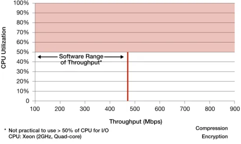
Some of the barriers for adding compression and security to communications links have to do with performance, cost, and power budget. The algorithms used in IPcomp and IPsec are very CPU intensive. As such, performing these functions can degrade the overall performance of the system. The compressed and encrypted throughput may also be inconsistent depending on the load of the CPU performing concurrent tasks. This would translate into poor service for subscrib-ers. The following chart illustrates the enormous amount of CPU resources taken up by performing compression and encryption in software.
100% 90% 80% 70% 60% 50% 40% 30% 20% 10% 0 100 200 300 400 500 600 700 800 900 Throughput (Mbps)
* Not practical to use > 50% of CPU for I/O CPU: Xeon (2GHz, Quad-core)
CPU Utilization
Compression Encryption
Software Range of Throughput*
Figure 4: CPU Loading from Software Compression/Encryption 8 Industry-standard compression protocol using LZS (Lempel-Ziv Stac) algorithm
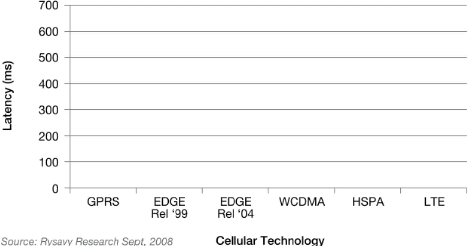
Each successive generation of mobile technology will also require network latency to decrease. Network latency is defined as the round-trip time for data to travel from the mobile unit through the wireless network. For example, the latency requirement decreased from over 600 ms in a 2G GPRS network to about 10 ms in 4G LTE networks. This is so operators can deliver an improved end-user experience for real-time and interactive applications such as online gaming, multi-cast, and VOIP.
700 600 500 400 300 200 100 0 GPRS EDGE
Rel ‘99 Rel ‘04EDGE WCDMA HSPA LTE
Cellular Technology
Latency (ms)
Source: Rysavy Research Sept, 2008
Figure 5: Network Latency Requirements Becoming More Stringent
Addressing the Challenge
Equipment manufacturers and network operators are left with a daunting problem: compressing/ encrypting backhaul links and reducing network latency – all while keeping costs and power con-sumption under control. Adding compression and security requirements typically increases latency, as those functions take many CPU cycles and memory copies/transfers to process a single packet. A faster, more expensive CPU can address throughput, but may not address the latency problem inherent in memory copies. The throughput may also be inconsistent depending on the load of other concurrent processes. The problem needs to be solved by specialized processors that completely offload compression and security functions from the host CPU while adding almost zero latency. The economics of using dedicated processors to perform specialized functions have been proven over time. However, as the specialized function matures, it eventually becomes integrated into the host CPU. Security processors have been in existence for many years and many embedded processors now have an integrated security core. However, these traditional security processing
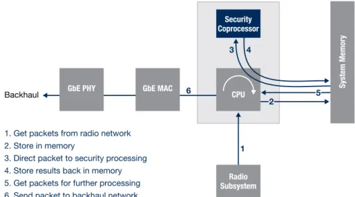
architectures still require the use of many memory copies/transfers to process a single packet – adding to latency. In security processor jargon, this configuration is known as a LookAside™ architecture. The following diagram illustrates the steps needed to process an IPsec packet.
Backhaul
1. Get packets from radio network 2. Store in memory
3. Direct packet to security processing 4. Store results back in memory 5. Get packets for further processing 6. Send packet to backhaul network
Security Coprocessor
GbE PHY GbE MAC
CPU Radio Subsystem 1 6 3 4 System Memor y 5 2
Figure 6: Data Flow in Traditional LookAside Architecture
Network equipment that support compression and encryption using LookAside architectures need to be designed with those functions in mind from the start; thus adding the functions to an existing design becomes impractical. Steps 3 and 4 in Figure 6 also use CPU cycles unnecessarily relative to a FlowThrough™ architecture (described below). When experiencing heavy CPU loads, those steps may be delayed – introducing additional latency.
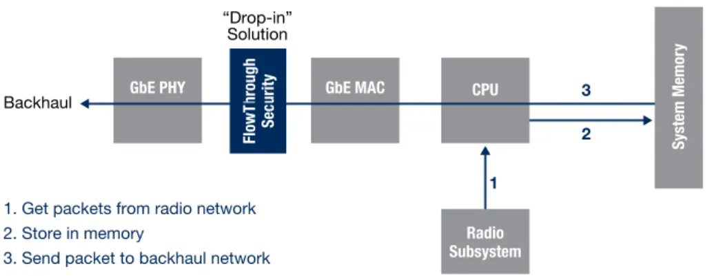
A better way to add compression and security to wireless backhaul is to use a FlowThrough processor. In this scenario, the CPU is relieved of all compression and encryption processing responsibility. The processor is added as a “drop-in” or “bump-in-the-wire” device between the MAC and PHY devices connected to the backhaul network. The following diagram illustrates how this solution simplifies and addresses the wireless backhaul challenge. As can be seen, the multi-hop journey of a packet to and from the host CPU is eliminated. The FlowThrough processor performs all of the steps necessary to compress the data and convert a clear-text IP packet into a secure IPsec packet to be transported to the backhaul network. A carefully designed FlowThrough device will also add minimal latency to the data path by using dedicated compression, crypto, and Public Key (PK) cores to process each packet.
Backhaul
“Drop-in” Solution
1. Get packets from radio network 2. Store in memory
3. Send packet to backhaul network FlowThrough Security
GbE PHY GbE MAC CPU
Radio Subsystem 1 3 2 System Memor y
Figure 7: Data Flow in FlowThrough Architecture
Hifn brings years of experience building hardware processors that perform the compression and encryption functions. FlowThrough processors completely offload those tasks from the host CPU, including algorithm and protocol processing. For example, Hifn’s 8450 processor compresses and encrypts data at up to 4 Gbps, enough to support two full-duplex Gigabit Ethernet links at line rate. Compression and encryption are done in a single pass.
The 8450 adds only 4 µs of latency and uses only 2.5 watts of power, making it ideal for wireless
backhaul applications. The 8450 supports on-chip IKE11 processing via one bank of inexpensive
DDR2 SDRAM12. The 8450 interfaces to other devices via standard gigabit Ethernet interfaces13.
11 IKE refers to Internet Key Exchange, a protocol used to set up security associations in IPsec 12 With optional ECC (error correcting code) memory
SGMll/ SerDes Ch 0 SGMll SerDes Ch 1 GMll/TBl RGMll/RTBl Control Port (RMll) SGMll/ SerDes Ch 0 RGMll/ RTBl SGMll/ SerDes Ch 1 ECC DDR2 SDRAM 32/39-bit Public-Key Engine Buffer Buffer Crypto Engine 1 Crypto Engine 0 Buffer Buffer Post Crypto Post Crypto SA RAM Code RAM Data RAM Code RAM Data RAM Memory Bridge DPU (Fast Path) Packet Queue Manager DMA Policy TCAM Post Crypto Processor RNG Control Plane Bridge eSC (Control Path) SerDes SerDes SerDes SerDes GbE MAC GbE MAC MAC GbE MAC GbE MAC
Figure 8: Block Diagram of Hifn’s FlowThrough Architecture
The control interface to the 8450 is achieved via in-band Ethernet frames via the Host Interface. However, an additional RMII (100Mbps Ethernet) interface offers an optional out-of-band control port. This port may also be used to establish an inter-chip link for multi-chip designs. The diagram below illustrates the steps that take place within the 8450 device.
To
Network ProcessingCrypto FetchSA FromHost
SAD RAM
SAD RAM SA’s
On-chip PolicyTCAM
SAL SAL MaskSA
SA
Lookup LookupPolicy
From
Network ToHost
SAD = SA Database SAL = SA Lookup table
TCAM = Ternary Content-Addressable Memory Source and destination IP address
Protocol (TCP/UDP/ICMP...) Source and destination port numbers
VLAN tag
Ethernet channel number (0 or 1)
SA
Lookup FetchSA ProcessingCrypto
Policy Selector
Check
Ethernet Link-Layer Ethernet Link-Layer
Ethernet Link-Layer Post-Cr
ypto Processing Post-Cr ypto Processing Ethernet Link-Layer IP H ea de r C he ck & Ex tra ct io n IP H ea de r C he ck & Ex tra ct io n
Figure 9: Process Flow in Hifn’s FlowThrough Architecture
The hardware comes with the IKE stack that is loaded into the SDRAM. It also comes with a software development kit (SDK) that provides the necessary application programming interfaces (API’s) to set up initial security policies. Once the policies are set up, the 8450 takes care of all processing associated with compressing and encrypting the traffic. Termination of IP and Ethernet is completely implemented on-chip, including fragmentation and reassembly of IP packets and ARP resolution for the Ethernet interface.
Summary
The evolution of wireless services from supporting plain voice to rich multimedia has increased the bandwidth requirements of backhaul connections. As network facilities are one of the highest contributors to a mobile operator’s costs, the backhaul connections are consolidating onto shared packet networks.
A Hifn FlowThrough processor provides mobile equipment vendors the ability to offer bandwidth optimization and protection with minimal software integration effort - all while remaining within the cost, power, and latency budget. The “drop-in” nature of the device also enables the quickest time-to-market for vendors.
For network operators, this means reduced facilities costs, improved quality of service, as well as meeting government compliance requirements with regard to protection of user data.