Technical Paper
Kevin Boyne, COO of UUNet mentioned at a recent talk at an MPLS conference at Virginia, USA that today’s opportunity is moving from Hypergrowth to Hyperscale, as the target traffic flow will go from 1 Terabit/s in 2000 to 10 Petabit/s (1 Petabit = 1000 Terrabit) in 2005, considering 10-fold growth every year.
Clearly, continuous innovations are needed to try and solve the traffic flow problems, while maintaining required traffic characteristics. After separate efforts by many companies to solve this problem, IETF as a body has proposed MPLS as a possible solution. There is extremely heated activity in this area currently, with Network Equipment
Manufacturers (NEMs, such as Cisco, Juniper etc.) rushing to implement MPLS on their devices, and Infrastructure Service Providers (SPs such as AT&T, Sprint stc.) trying to utilize this new technology to their advantage.
Testing Multi-Protocol Label
Switching (MPLS) enabled
Networks
The Problem
Let’s start with the overall problems that we are trying to solve here, and look, very briefly, at how each can be answered by MPLS, and what aspects of MPLS, in turn, that we need to test.
User Perspective:
Problem 1: Voice (over IP networks)
Customer: Millions of people trying to hold personal conversations millions of others across the globe
Service required: A smooth, jitter-free conversation, and without having to wait for 1 sec after speaking to expect the other person to respond, and without having to redail a number of times due to unavailability of service.
Problem 2: Video (over IP networks)
Customer: A large multinational company trying to hold a video conference over various sites all across the globe
Service required: A smooth, jitter-free conference, and without having to wait for up to 1 sec after speaking to expect the other person to respond and without having the voice and video to be out-of-sync with each other.
Problem 3: Financial Transaction
Customer: A broker in New York trading on the Singapore money market. Service required: A very fast, secure and fully accurate transaction. Problem 4: Sensitive Data Transfer.
Customer: A field salesperson accessing company’s internal database to get sensitive information on competitors and customer. Service required: A completely secure transaction.
And all the above services are to be provided at the minimum cost to the customer so as to remain competitive in the exploding growth path.
Service Provider Perspective:
Other than the above services which a Service Provider will have to provide, the other network issues that the SP must resolve are as follows.
Problem 1: Effective bandwidth utilization. One section of the network remains more congested or loaded while other parts are not loaded at all due to Shortest Path First (SPF) Routing.
Solution required: A way to route around congested shortest paths and duplicate the capabilities available in previous generation ATM or FR networks
Problem 2: There is large amount of pre-deployed equipment which has to be interconnected
Solution required: A unified IP control plane to simplify management of network (as opposed to overlay of IP over ATM or FR). Problem 3: The need to support new services e.g. managed VPNs.
Solution required: A way to provide these new services.
Problem 4: A lot of manual intervention required at present for Network Management
Solution required: More automation, moving towards a self managed network, which would translate into lower maintenance costs and higher profits.
Network Service Quality
All of the above then, bring us to discuss the characteristics of the overall network that are to be used. These characteristics (which are referred to as Quality of Service - QoS) are to be provided by Infrastructure Service Providers (SP) who manage the networks. In many cases, the SP’s are going to sign contracts called Service Level Agreements (SLAs) and these will detail the QoS they promise to provide to their customers.
Note that while the individual consumer (ref. Problem 1) does not sign an SLA with the SP, he/she can switch to another competitor SP if the perceived service level is lower than expected.
Thus it becomes evident that some of the characteristics to be aspired after are as follows (but not necessarily in the order of importance):
a. Uninterrupted service availability (packet loss, connection drop) b. Complete security
c. Predicable latency/ delay
d. Predicable jitter - (packet delay variance, burstiness)
The points c. and d. boil down to stating that the aim is preservation of the real time characteristics of the traffic flow. To sustain this, the service provider attempts to balance the traffic flows in the network. This brings up a requirement to have external influence on Network management so as to ensure that one part of the network does not become more congested than the other.
The above may seem straightforward, but this translates to the activity we have seen and continue to see in the various forums for the Internet building technologies such as Internet Engineering Task Force (IETF), Information Technology and Telephony Union (ITU-T), and the ATM Forum. There are other supporting bodies such as the Quality of Service (QoS) Forum and MPLS Forum. All in all, these groups and a large number of other groups are working towards a ’better’ Internet, so that we can achieve the aforementioned characteristics.
The Services and Financial Angle
All this must translate into revenues for the SP’s. We presume that all this is going to cost a lot of money to build and provide. To charge the customers then, there has to be well defined services.
One obvious way is to charge as per the Service Level provided to the customer in the SLA signed.
Currently, many SP’s provide services such as - Gold, Silver and Bronze, and of course, best effort, and would charge customers as per flow parameters such as the guaranteed bandwidth, packet loss, maximum latency etc.
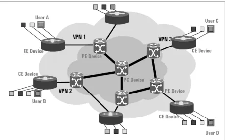
The other way will be charging for services such as a Virtual Private Network (VPN) provided to a customer who has connectivity requirements from multiple remote locations (ref. Figure 1).
One other important feature requirement for the SP’s was to have a traffic distribution technology which will not have to throw away all of the current infrastructure. MPLS, with its approach of not caring about what the layer 2 protocol is, seems to have met this requirement. MPLS does this by using IP routing information and does not have its own routing protocol.
Figure 1: A typical Service Scenario
8VHU$
&('HYLFH &('HYLFH
8VHU%
8VHU&
8VHU' &('HYLFH
&('HYLFH
931 931
931 931
931 931
3&'HYLFH 3('HYLFH
What does MPLS offer
MPLS allows the SP network manager to set up explicit routes (with pre-defined characteristics) or tunnels across various routers on the network, and plan so that the undesirable features such as jitter, delay, packet loss etc. can be reduced,. Guaranteed service levels as well as services such as VPN can be provided.
A simple map could be as follows:
Finally, these steps are probably to move towards a grand scale, self-managed network which will translate to lower maintenance costs and higher profits for the Service providers.
A detailed discussion of the MPLS features is beyond the scope of this paper and there have been many documents on this. Please look up the documents listed in the reference section of this paper.
The rest of this paper will focus on the various issues involved with testing the features of MPLS, which have made MPLS such an important technology.
Service/Network Characteristics
desired by End-user or Service
Provider
The relevant MPLS features
Low connection loss / packet loss
Traffic Engineering (TE) feature which
allows for multiple Explicit Routes (ER) for
the same source-destination for fast
restoration
Low jitter
TE/ER
Low latency
TE/ER
High security
MPLS VPN support – with the caveat that
there is no encryption (IPSec maybe used)
Balanced traffic distribution
TE/ER to route around congested shortest
paths
Independence from layer 2
(co-existence of IP, ATM and Optical
networks)
MPLS architecture
Co-existence of MPLS and non-MPLS
networks
MPLS architecture
Various service levels e.g. Gold etc.
Service QOS guarantees using TE and
Differentiated Services (DiffServ)
MPLS Testing Issues
Before we start discussing the various issues, two terms that will be used quite interchangeably are - Implementation under Test (IUT) and System Under Test (SUT). The reason why they are interchangeable is because an IUT runs on one or more SUT. IUT and SUT denote the MPLS protocol implementation or MPLS-enabled device(s) being tested respectively. The MPLS-enabled device could be a switch or a router. Also, let us consider that a test product ‘Tester T’ will help us test these. As we go along the testing requirements, we will also keep defining the features that the test product Tester T must have.
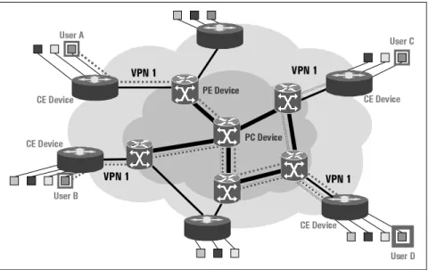
We will start with a sample problem which we have discussed earlier, and try to see how we can use Tester T to test that a MPLS network is providing a solution to the problem. Problem: A large multinational company trying to hold a video conference over various sites. Consider that this is a typical centrally managed conference call, so people have to connect to a coordinating office site over a Service Provider's network of routers and switches, which have to support multicast video and provide QoS guarantees. As some sites are remotely located, VPN support is essential. We will assume the Service Provider network is mainly MPLS for now. MPLS will be used to set up traffic paths, which are called Label Switched Paths (LSP's), using the existing IP Routing protocols (which are being extended) and new MPLS Signaling protocols and send data traffic over these paths. The SP wants
to provide this service and wants to be certain that the network will be able to do this reliably. Refer to the figure 2.
First, we have to ensure that every unit (individual device) to be deployed in the network works. Now, there are two components to this - the software and the hardware. The focus here will be to take an integrated testing approach to ensure that the unit works as a whole.
Now, the SUT can be either a Network Edge router (Provider Edge or PE) or a Network Core router (Provider Core or PC). (Refer figure 2)
As we want to ensure that unit will work in a large network -(depending on the size of the network of the SP) - there is a need for the Tester T be able to emulate the same size of network and emulate all the elements of the network. To achieve this, Tester T will be made up of one or more devices with multiple physical interfaces connected to the SUT.
At this point it would be appropriate to also mention that there are two competing signaling protocols for MPLS - LDP/CR-LDP (Constraint based Routing using Label Distribution Protocol) and RSVP-TE (Resource Reservation Protocol using Traffic Engineering Extensions). RSVP-TE is an extension of the long existing RSVP protocol and comes with certain legacy issues. CR-LDP is a newly designed protocol and is being ‘improved’ fast to match all the features that RSVP-TE offers.
Figure 2: A multinational company trying to set up VPN’s across its Service Provider’s MPLS enabled network
8VHU$
&('HYLFH &('HYLFH
8VHU%
8VHU&
8VHU' &('HYLFH
&('HYLFH
931
931
931
931 931931
3('HYLFH 3&'HYLFH
931
First, each interface on the Tester T has to be able to emulate an adjacent router and a virtual topology behind the adjacent router. These interfaces will connect to the SUT, which may be a single router or collection of Routers. This allows for a variety of test configurations:
1. Test SUT as a Provider Core (PC) i.e. an intermediate label switched router (LSR): Here the Tester T interfaces emulate connected LSRs and many virtual edge devices in the simulated topology behind the interface. Here, the aim is to test the correct label switching behavior of SUT.
2. Test SUT as a Provider Edge (PE) i.e. a router on the edge of the MPLS cloud: Here some of the Tester T interfaces emulate devices within the MPLS cloud and other interfaces emulate non-MPLS router beyond the edge. Here, the aim is to test ability of SUT to correctly push and pop labels and forward labelled and unlabeled packets correctly.
A. Functional and Conformance Testing
To start with, we have to do functional and conformance testing to ensure the basic MPLS functionality works. We will consider that the SUT supports any one of the MPLS Signaling protocols amongst LDP/CR-LDP and RSVP-TE, as well as at least one Internal Gateway Protocol amongst OSPF and IS-IS. The overall test requirements will be the same for any set of the protocols, while some of the packet details will naturally be different. Conformance testing will not be discussed in details here, but we must mention that Conformance testing is to pay a lot of attention to the protocol specification details to ensure that the SUT or IUT can handle positive (correct) as well as negative situations (malformed packets, out-of-state or out-of-sequence messages).
Basic MPLS forwarding tests
The basic MPLS test scenario is to support a (any) Label Distribution Protocol in order to signal the creation of Label Switched Paths (LSPs). This is to evaluate that each interface on the SUT can correctly forward labeled MPLS packets and push or pop labels appropriately. This scenario could use LDP, RSVP or even BGP4.
In figure 4, a typical RSVP-TE scenario has been described. Here, Tester T will emulate two edge routers RA and RB, which are connected to interface (I/F) 1 and I/F 2 of the SUT. If PE Router RA wants to
send data to RB, it needs to set up an LSP to PE Router RB, then the following steps will be followed. Once RA and RB are physically connected to the SUT, and the IGP, say OSPF, is enabled on all interfaces, OSPF will exchange routing information between the devices, so that the SUT’s routing table has information about RA and RB. RA will now send a Path message to the SUT with the target router as RB. If the RSVP implementation in the SUT is working, then the SUT will forward the Path message to RB after adding some information. RB will then send a Reservation (RESV) message back to SUT with a label (L1) for the RSVP tunnel, and the SUT, in turn will send a Resv message to RA with another label (L2). At this point, a label table should exist at emulated router RA and the SUT. Now, data can be sent from a traffic generator at RA, which will send the data packets with the label L2 from the label table plugged onto the IP header. If the SUT works correctly, then it will strip (pop) the label L2 and push in label L1 onto the data and forward it to RB.
'87
'87
5
5$$
5
5%%
5
5&&
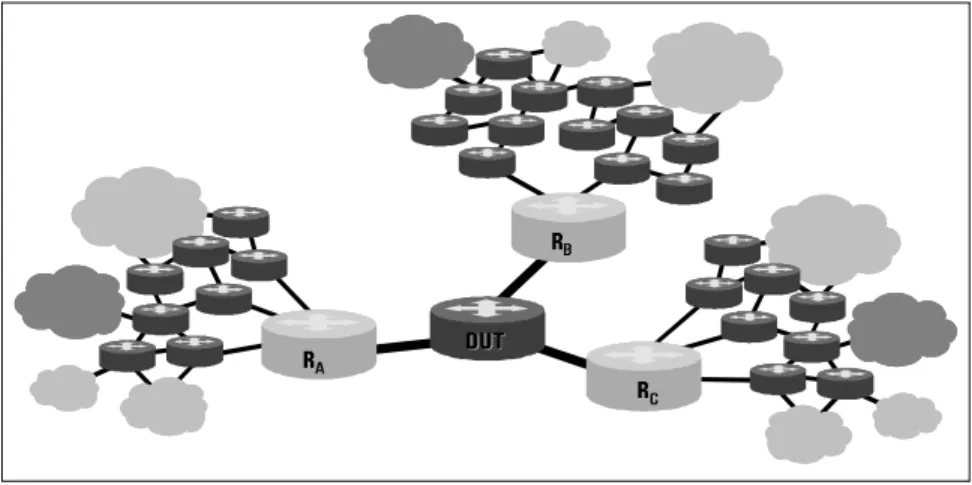
Figure 3: A typical test network with emulated elements
Figure 4: A typical RSVP Functional test scenario
5(69
5(69
5(69
5(69
5
5%% 7UDIILF *HQHUDWRU
6:$3
6:$3
323
323
386+
386+
3$7+
3$7+
3$7+
3$7+
'87
'87
5
those for the RSVP protocol. LDP has a full state machine while RSVP has a soft state machine, and LDP also differs from RSVP in that it requires only one TCP session for all LSP’s between two peer routers, while RSVP requires a separate socket session for each LSPs. LDP also has a concept of Forward Equivalence Class (FEC). In Tester T, let us assume that we want to send data from a non-MPLS source connected to PE Router RA to a FEC which lies behind RB, and hence set up an LSP to PE Router RB.
So, the routers will first traverse the steps in the LDP state machine and go through the exchange of LDP Hello messages followed by Initialization and Ack messages. Once this is done, RA will send a Label Request message to the SUT, with the target router as RB. If the LDP implementation at SUT is working, then the SUT will in turn send a Label Request to RB. RB will then send a Label Mapping message back to SUT with a label L1 for the LSP, and the SUT, in turn will send a Label Mapping message to RA with another label L2. At this point, a label table should exist at emulated router RA and the SUT. Now, data can be sent from a traffic generator at RA, which will send the data packets with the label L2 from the label table plugged onto the IP header. If the SUT works correctly, then it will strip (pop) the label L2 and push in label L1 onto the data and forward it to RB.
Note that the term SUT applies to one or more devices under test, and we can check the above scenarios using more than one PC device between the emulated PE routers.
As a changed scenario, we can replace RA or RB with a real router and try the same scenario. This way, we can also exercise the PE functionality of the SUT. If we use the SUT as the tail end (destination
PE), we can check whether it sends back a correct Label Mapping or Resv message back, and also pops out the label from the data sent to it correctly. If we use the SUT as the head end (source PE), then we will have to induce it to send out a Label Request or Path Message, and then induce a traffic flow through the PE to check whether it puts in the label properly.
B. Performance and Stress Testing
Now that we know that the SUT can set up LSP’s and send data correctly, we need to ensure that when the SUT is put into the network, it will support the traffic engineering (TE) functionalities of MPLS properly. This involves support for RSVP-TE or CR-LDP and the TE extensions to both OSPF and IS-IS. For this style of testing each Tester T interface will advertise an emulated topology including TE link information, by forming OSPF/IS-IS adjacencies over its physical
connections with the SUT. The TE information carries values of the various Quality of Service (QoS) parameters supported by the Signaling protocols.
The Tester T should be able to act as upto all but one element of the above network, except that it will never act as a stand-alone PC router. RSVP-TE or CR-LDP can be used to initiate LSPs (i.e. simulate the head-end of a large number of tunnels by initiating RSVP PATH or LDP Label Request messages) or reply to PATH messages received from the SUT with RESV or Label Mapping messages and label bindings. Labeled traffic can then be sent on those tunnels. Now we can talk about setting up a very large number of LSP’s at a fast rate, and then send data over these LSP’s at up to line-rate. This will allow us to measure forwarding performance of the MPLS-enabled Routers.
'87 '87 5
5$$
5 5%%
5 5&& Figure 5: A typical LDP Functional test scenario
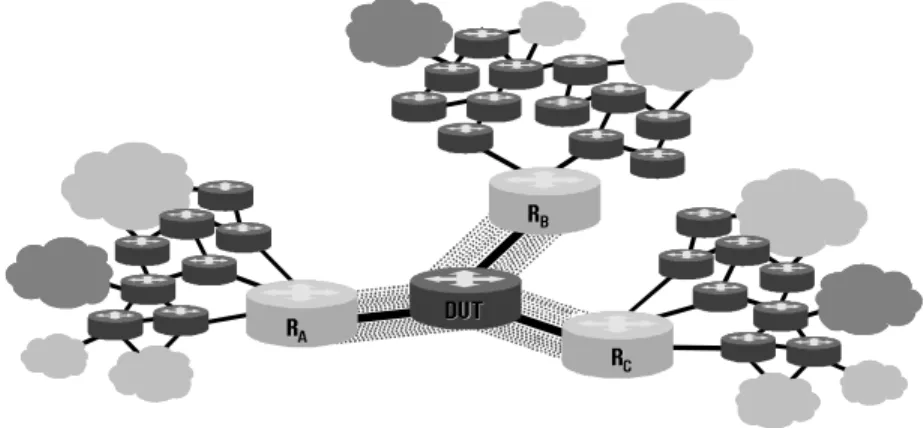
Figure 6: An emulated Network used for Performance and Stress Testing
+HOOR +HOOR ,QLWLDOL]DWLRQ ,QLWLDOL]DWLRQ +HOOR +HOOR ,QLWLDOL]DWLRQ ,QLWLDOL]DWLRQ )(& /DEHO /DEHO 5HTXHVW 5HTXHVW /DEHO /DEHO 0DSSLQJ 0DSSLQJ '87 '87 5
5%% 5 5$$ 7UDIILF *HQHUDWRU 6:$3 6:$3 323 323 386+ 386+ /DEHO /DEHO 5HTXHVW 5HTXHVW
Some typical test scenarios for MPLS TE include:
1. LSP setup time: How long does it take to establish a new LSP i.e. the time difference between the LSP setup message (PATH, Label Request) going out and response (RESV, Label Mapping) message reaching back at the head-end. This can be tested by the same setup as in Figures 4 and 5, except that we will now keep on setting up a large number of LSP’s. We can timestamp the setup and response, and measure the difference between the time values. There are two ways we can try out this - first, without any data flow, just to stress the IUT software, and secondly, with data flowing over the LSP’s being setup. In the latter case, we can tweak the traffic and increase it gradually to reach line rate, and see the SUT’s LSP setup time variation under different router stress conditions. Another way the latter scenario can be achieved is if we connect the SUT’s non-MPLS interfaces to another network, where the SUT is handling traffic at line-rate, while LSP’s are being setup on two of its links (ref Figure 6).
2. LSP setup rate: How many LSP’s can be established per second - this again can be measured by setting up LSP’s fast, under low to high traffic load in the manner mentioned before.
3. IGP TE convergence time: After an LSP is established, how long does it take for the SUT to emit all updated IGP TE updates - this can be measured at high LSP setup rates, as well as high data rates.
Other than the typical performance measures as listed so far, MPLS provides certain features, which become critical for recovery from any kind of network link failure. To recover quickly from link failure situations, so that the service characteristics remain uniform, backup LSP’s may be set up over other network segments between the same source and destination. At the time of link failure, a fast reroute is done to change the traffic path to the backup LSP. The same feature may be used for another situation - change of service level for the same source-destination pair. For example, the bandwidth requirement of a particular traffic flow may change, say new users join in an existing video conference. In that case, a new LSP may be set up over the same network, and then traffic is seamlessly moved over to the new backup LSP, and the old one is torn down after the transfer is complete (’make before break’).
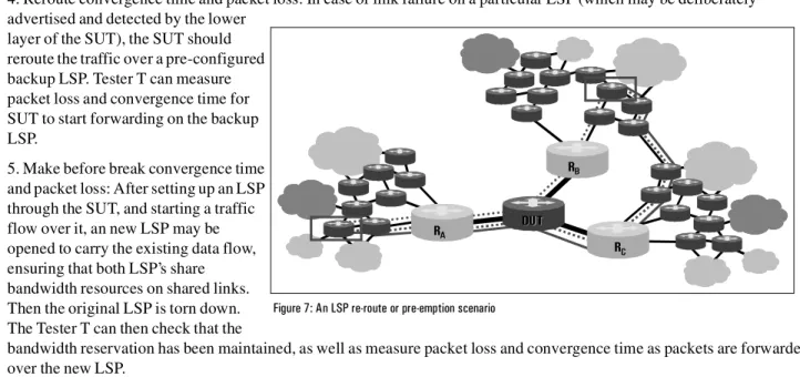
4. Reroute convergence time and packet loss: In case of link failure on a particular LSP (which may be deliberately advertised and detected by the lower
layer of the SUT), the SUT should reroute the traffic over a pre-configured backup LSP. Tester T can measure packet loss and convergence time for SUT to start forwarding on the backup LSP.
5. Make before break convergence time and packet loss: After setting up an LSP through the SUT, and starting a traffic flow over it, an new LSP may be opened to carry the existing data flow, ensuring that both LSP’s share bandwidth resources on shared links. Then the original LSP is torn down. The Tester T can then check that the
bandwidth reservation has been maintained, as well as measure packet loss and convergence time as packets are forwarded over the new LSP.
Another important feature of MPLS is the ability to ensure that high priority traffic (which has low delay and jitter tolerance, e.g. voice) gets special treatment in terms of bandwidth reservation. This feature is called Tunnel pre-emption where an existing LSP with low priority can be ’bumped off’ by a new LSP with higher priority.
6. LSP pre-emption feature: Consider three emulated PE devices RA, RB and RC connected to the SUT as in Figure 7. Now,
an LSP can be created between RA->SUT->RB, with a low priority with a certain bandwidth reservation, say X, where total
bandwidth on the link RA->SUT is B. Now, Tester T can attempt to create a higher priority second tunnel from
RA->SUT->RC that exceeds the available bandwidth (B-X) on the link RA->SUT.Now, Tester T can check that the attempt
to establish the second LSP causes the SUT to "pre-empt" the first (i.e. it is torn down).
'87 '87 5
5$$
5 5%%
5 5&&
C. Integrated Functional Testing
One more type of test that does not really fit in Performance testing, but rather into an integrated functional test category is a test of constraint based SPF calculation of the SUT. Here Tester T can advertise a set of constraints (bandwidth reservations, resource classes/colors) for each link in the IGP. When SUT initiates an LSP setup message, then Tester T can validate the explicit route object (ERO) against the expected constraint based shortest path. Also, as LSP’s do get set up and link resources start getting used up, this information needs to be advertised by the IGP, and that can be checked by Tester T.
D. Service Testing
Service Testing includes ensuring the service level committed by an SP is actually being provided.
1. SLA QoS testing: This is similar to performance measurements discussed earlier, except that the Tester T may emulate more realistic situation instead of going for unlimited stress scenarios. Here, a test network of one or more SUT can be set up and after setting up of a number of LSP’s and traffic flows over those LSP’s over the network, the Tester T can measure whether the QoS provided actually matches that promised or negotiated by the MPLS-TE parameters. If a realistic situation demands stress scenarios of various kinds, those may be emulated for testing.
2. SLA CoS testing: This is part of the new feature - Differentiated Services (DiffServ) being recently discussed at the IETF. This allows the SP’s to have another level of control over the traffic flow through any PE or PC router. This feature can be tested in the same way as for SLA QoS testing.
The other category of testing would be the testing of services such as Virtual Private Network (BGP4/MPLS VPN). However, this is a whole area of testing in itself.
E. Total Network Testing - using VPN Service as an example
This is the final point of testing, where we bring in all the elements of the network. This incorporates all the diversity allowed by MPLS. In this scenario, the Customer of the SP’s also needs to be represented, as the VPN’s can be defined and managed at Customer Edge (CE) routers. As the networks at the CE may be much more diverse from the PE/PC router network, there is an added
complexity in this kind of testing. We will touch upon some of the testing possibilities in this area.
For the testing of this nature, there will be a large number of interfaces required on Tester T. Each interface of the Tester T can emulate either a customer edge (CE) Router, a PE Router and PC router within the MPLS cloud with the appropriate network elements. This type of test can again be applied onto a single or multiple devices under test, but probably will be more meaningful when there are more than one SUT.
Some test interfaces will also emulate customer edge devices running non-MPLS protocols such as RIP or basic OSPF. Other test interfaces can emulate the MPLS cloud running OSPF or IS-IS, to advertise topology of MPLS cloud, and then RSVP-TE, and/or LDP/CR-LDP to create LSP’s to emulated PE’s. MP-IBGP (multi-protocol internal BGP) can also be used to advertise VPN routes (NLRI + VPN Route Distinguisher + Label) between PE routers.
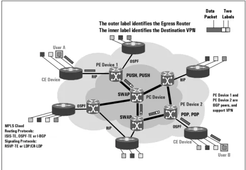
Figure 8: A possible real-life VPN scenario
'DWD 3DFNHW /DEHOV7ZR
8VHU$ 6:$3 6:$3 386+386+ 386+386+ 6:$3
6:$3 323323323323
&('HYLFH &('HYLFH 8VHU% 7KHRXWHUODEHOLGHQWLILHVWKH(JUHVV5RXWHU 7KHLQQHUODEHOLGHQWLILHVWKH'HVWLQDWLRQ931 03/6&ORXG 5RXWLQJ3URWRFROV ,6,67(263)7(RU,%*3 6LJQDOLQJ3URWRFROV 56937(RU/'3&5/'3 263) 263) 5,3 5,3 5,3 5,3 263) 263) 5,3 5,3 263) 263) 3('HYLFH 3&'HYLFH 3('HYLFH 3('HYLFHDQG 3('HYLFHDUH %*3SHHUVDQG VXSSRUW931
Here the most interesting test scenarios can be created for the SUT when it acts as the PE router. Tester T can emulate various elements as listed above and can perform the following test scenarios.
1. Basic Functionality Testing:
a. Test per-customer forwarding tables: check for correct updates
b. Establish RIP, OSPF adjacencies on CE side: check proper establishment
c. Establish OSPF/IS-IS, RSVP and BGP4 on MPLS side: check proper establishment
d. Advertise the same routes using RIP and/or OSPF from two disjoint customers, and test that these routes are propagated using BGP4 to the appropriate simulated PE peers with unique Route Distinguishers and Labels e. Forward labeled MPLS packets to the PE and ensure the packets are correctly forwarded to the correct customer f. Advertise VPN routes for a particular set of customers using BGP4 (NLRI + Route Distinguisher + Label), and test that these routes are propagated to the correct customer using RIP or OSPF
g.Send IP traffic to the set of destinations advertised by BGP4 from the customer where the routes were received and check whether traffic is correctly forwarded
h. Ensure that packets are received on the MPLS side with the appropriate label stack (top label = LDP or RSVP label to PE, next label = BGP4 label which identifies customer routes)
2. Scalability and Performance Testing:
The above then can be scaled to support a very large simulated MPLS cloud (1000s of nodes), with 100s of simulated PE routers and 100-1000s of simulated customer edge routers. Send a full mesh of IP and labelled traffic between all devices in this simulated topology. Measure forwarding performance (correctness, throughput, latency and loss) at high
forwarding rates and measure continued operation of all of the routing protocols under this traffic and routing load.
MPLS Test Tools from Agilent Technologies
Agilent has two product lines the QARobot and the Router Tester. The rich set of features of these two products allows us to create all the scenarios mentioned above.
The QARobot product’s capability to scale control protocol and Router Tester’s capability of producing line-rate traffic and making line-rate measurements accurately makes every test scenario discussed completely viable. These products could act as the
aforementioned Tester T in different test scenarios, and the product to be used would be determined by the tester functionality requirements.
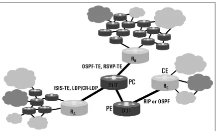
With reference to Figure 9, Agilent’s test tools can act as any one or more elements of the network displayed, except being a stand-alone Provider Core router. Also, more than
one of Agilent’s test tools can be connected over multiple interfaces to the network of SUT (network may consist of one or more devices), and ’surround’ the System Under Test (SUT).
'87 '87
5 5$$
5 5%%
5 5&&
&(
3( 5,3RU263)
263)7(56937( ,6,67(/'3&5/'3
'87 '87 3&
References
1. B. Jamoussi, et., al., "Constraint-based LSP Setup Using LDP", Work In Progress, June 2000. 2. L. Andersson, et., al., "LDP Specification", Work In Progress, June 2000.
3. D. Awduche et., al., "Requirements for Traffic Engineering Over MPLS", RFC 2702, September 1999.
4 D. Awduche, L. Berger, D. Gan, T. Li, G. Swallow, V. Srinivasan, "Extensions to RSVP for LSP Tunnels," Work In Progress, February 2000
5. D. Awduche, J. Malcolm, J. Agogbua, M. O’Dell, J. McManus, "Requirements for Traffic Engineering Over MPLS," RFC 2702, September 1999.
6. Rekhter, Rosen,"Carrying Label Information in BGP-4", Work In Progress, January 2000.
7. E. Rosen, A. Viswanathan, R. Callon, "Multiprotocol Label Switching Architecture ", Work In Progress, July 2000. 8. Rosen et al., "BGP/MPLS VPNs", Work In Progress, draft-rosen-rfc2547bis-01.txt, May 2000.
9. Braden et al., "Resource ReSerVation Protocol (RSVP) - Version 1 Functional Specification", RFC-2205, September 1997. 10. S. Blake, D. Black, M. Carlson, E. Davies, Z. Wang, W.Weiss, "An Architecture for Differentiated Services", Work In Progress, October, 1998.
11. Tony Li, Henk Smit, "IS-IS extensions for Traffic Engineering", Work In Progress, September 2000. 12. Francois Le Faucheur et al., "MPLS Support of Differentiated Services", Work In Progress, August 2000.
Copyright © 2000 Agilent Technologies Specifications subject to change. November 1, 2000.