Analysis the effect of condenser pressure (vacuum) on efficiency
and heat rate of steam turbine
1
Muvva Murali Krishna 2K .Mohan Krishna 3A.V.Sridhar 4J Hari Narayana Rao
1
M. Tech. Student,
3Assistant.Professor
3Associate.Professor,
Dept of ME, KITS, Divili.
4
Research Scholar
ABSTRACTElectricity plays a vital role in our daily life. The power demand is increasing day by day due to increasing the population. The power is required for Industrialization and development of nation. Our country mainly depends on thermal power plant for electrical supply. In thermal power plants turbine is considered to be HEART of the plant. Maintained required condenser parameters to improve the performance of turbine and these parameters direct impact the economical growth of power plant
This project involves the construction features, start up, and Shut down, emergency operation and safety protections o f the 32 mw steam turbine.
The main aim of this project is analysis the how to effect the condenser pressure (vacuum) on efficiency and heat rate of regenerative steam turbine by mathematical calculations.
I. INTRODUCTION
Steam turbine is prime-mover which converts heat energy of steam to mechanical energy. When steam is allowed to expand through an orifice then heat energy (enthalpy), is converted into kinetic energy. This kinetic energy of steam is changed to mechanical energy through the impact (impulse) or reaction of steam against the blades. The force of steam is used to spin the turbine blades which spin the generator, producing electricity
1.1Throttle governing:
In throttle governing the pressure of steam is reduced at the turbine entry thereby decreasing the availability of energy. In this method steam is allowed to pass through a restricted passage thereby reducing its pressure
across the governing valve. The flow rate is controlled using a partially opened steam stop valve. The reduction in pressure leads to a throttling process in which the enthalpy of steam remains constant.
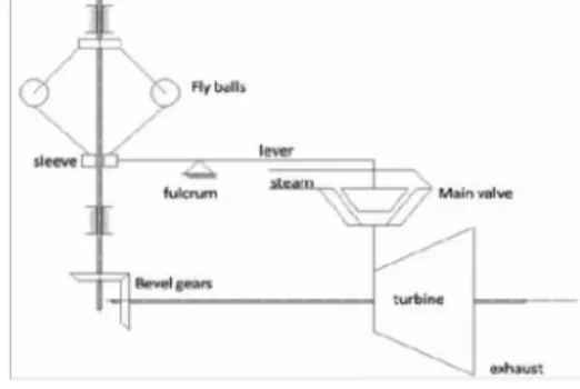
Fig. 1 Schematic of throttle governor
1.2 Throttle governing–small turbines:
Low initial cost and simple mechanism makes throttle governing the most apt method for small steam turbines. The valve is actuated by using a centrifugal governor which consists of flying balls attached to the arm of the sleeve. A geared mechanism connects the turbine shaft to the rotating shaft on which the sleeve reciprocates axially.
With a reduction in the load the turbine shaft speed increases and brings about the movement of the flying balls away from the sleeve axis. This result in an axial movement of the sleeve followed by the activation of a lever, which in turn actuates the main stop valve to a partially opened position to control the flow rate.
2. COMPONENTS OF STEAM TURBINE:
Analysis the effect of condenser pressure (vacuum) on efficiency
and heat rate of steam turbine
1
Muvva Murali Krishna 2K .Mohan Krishna 3A.V.Sridhar 4J Hari Narayana Rao
1
M. Tech. Student,
3Assistant.Professor
3Associate.Professor,
Dept of ME, KITS, Divili.
4
Research Scholar
ABSTRACTElectricity plays a vital role in our daily life. The power demand is increasing day by day due to increasing the population. The power is required for Industrialization and development of nation. Our country mainly depends on thermal power plant for electrical supply. In thermal power plants turbine is considered to be HEART of the plant. Maintained required condenser parameters to improve the performance of turbine and these parameters direct impact the economical growth of power plant
This project involves the construction features, start up, and Shut down, emergency operation and safety protections o f the 32 mw steam turbine.
The main aim of this project is analysis the how to effect the condenser pressure (vacuum) on efficiency and heat rate of regenerative steam turbine by mathematical calculations.
I. INTRODUCTION
Steam turbine is prime-mover which converts heat energy of steam to mechanical energy. When steam is allowed to expand through an orifice then heat energy (enthalpy), is converted into kinetic energy. This kinetic energy of steam is changed to mechanical energy through the impact (impulse) or reaction of steam against the blades. The force of steam is used to spin the turbine blades which spin the generator, producing electricity
1.1Throttle governing:
In throttle governing the pressure of steam is reduced at the turbine entry thereby decreasing the availability of energy. In this method steam is allowed to pass through a restricted passage thereby reducing its pressure
across the governing valve. The flow rate is controlled using a partially opened steam stop valve. The reduction in pressure leads to a throttling process in which the enthalpy of steam remains constant.
Fig. 1 Schematic of throttle governor
1.2 Throttle governing–small turbines:
Low initial cost and simple mechanism makes throttle governing the most apt method for small steam turbines. The valve is actuated by using a centrifugal governor which consists of flying balls attached to the arm of the sleeve. A geared mechanism connects the turbine shaft to the rotating shaft on which the sleeve reciprocates axially.
With a reduction in the load the turbine shaft speed increases and brings about the movement of the flying balls away from the sleeve axis. This result in an axial movement of the sleeve followed by the activation of a lever, which in turn actuates the main stop valve to a partially opened position to control the flow rate.
The main components in the steam turbine are mentioned below:
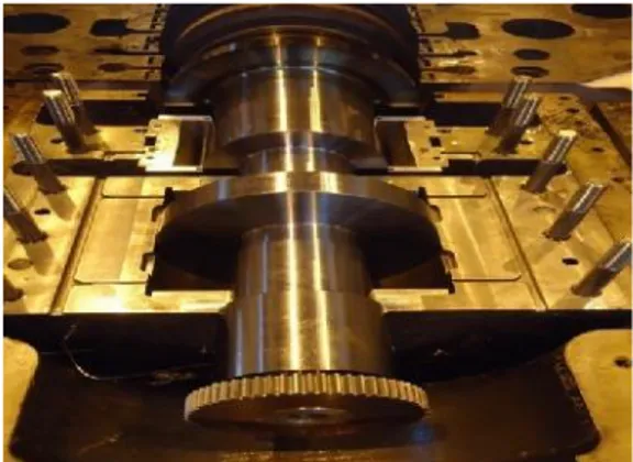
2.1Pedestal, Base Plate and Fixed Points:
The Turbines rest on the pedestals. The front pedestal houses the governor. The center pedestal houses the combined journal and thrust bearing and the other pedestals contain one journal bearing each. All pedestals are of fabricated construction. The front pedestal and the center pedestal slide over their respective base plates, which are fixed to the foundation. While the LP front and rear pedestals themselves are fixed to the foundation. On the rotating system the fixed point is provided by the thrust bearing. The LP pedestals also carry the shaft seal housing which is joined to the LP outer casing with compensators. Hence these gland clearances remain unaffected by any deformation of LP cylinder during operation.
Fig. 2 Turbine base plate with front bearing pedestal
2.2 Balding:
The turbines balding are designed for maximum efficiency and reliability. Blades are single most costly element of turbine. Blades fitted in the stationary part are called guide blades or nozzles and those fitted in the rotor are called moving or working blades. The following are three main types of blades:
Cylindrical or constant profile blade.
Tapered cylindrical profile blade.
Twisted and varying profile blade. The HP blades are machined from rectangular bars stock with integral shroud and T-root. The root and shroud have rhomboid shape in order to have an additional clamping force at root and a movement at shroud for increase rigidity of blade assembly. The blades are locked radially into grooves of casing/rotor with
the help of fitting pieces called caulking brass. The guide blades in the medium and low temperature regions are made from solid drawn material and have a hook type root. In this case shrouding is separating under riveted in position. The root is brazed on to the blade. These blades are locked axially in the casing groove, with the help of precision cast clamping pieces to achieve tight fitting.
These LP blades are suitably along their height to suit the different peripheral velocities from the root to tip. The profiles are also made tapered to obtain most favorable stress distribution in the profile. The trailing edge of these blades is very thin to avoid formation of streams of water.
The axial distance between the last stages is kept large facilitate breaking of any water droplets which may still remain. The leading edges of the last stages are flame hardened to give protection against erosion. Suitably sized longitudinal suction slits are provided in the last stage guide blades to remove the water to the condenser accumulated on the profile boundaries due to wetness of steam.
Fig. 3 HP Blades (shrouded blades)
2.3Bearings:
The bearings are made in two halves and are all tilting type. The Rotor is supported by two bearings. Bearing Babbitt temperatures are measured by the thermo couples directly under the white metal. The temperature of the thrust pads is measured by the thermo couples in two opposite pads on both turbine side and generator side. Lube oil is admitted in the oil spaces that are milled into the bearing shells at the horizontal joint and are open to the shaft journal.
There are two types of bearings mostly used in turbine are
1.
Journal bearings2.
Thrust bearings2.3.1 Rotor:
If the turbine is impulse type the rotor is disc type i.e. blades are carried in the discs, which may be integral forged with shaft or shrunk on the shaft. Each rotor is subjected to 20% over speed test and is balanced at 4909rpm. The rotors carry the moving blades. The shaft seals are axial. All the rotors are dynamically balanced to every fine degree of precision; this ensures that there are minimum vibrations and dynamic loading of bearings. Labyrinths with the sealing strips caulked into the shafts. Sealing in turbine casings is provided to check steam leakage from HP side and air leakage into LP side
.
Fig.5 32MW Turbine rotor
2.4 Glands:
In the HP the seals consist of a series of sealing strips caulked alternatively in the shaft and into stationary rings. In the case of LP glands sealing strips are fitted in the stationary rings only. Each sealing ring consists of 6 or 8 segments and is carried in grooves in the casing to allow radial movement. Each segment is held in position against a shoulder by two coil springs. Both fixed and moving blades are fitted with a continuous shroud in which steps have been machined to produce a labyrinth. The sealing
strips are caulked into the casing and shaft opposite to the blade and are of stainless steel which can be easily replaced.
Turbine shaft glands are sealed with auxiliary steam supplied by an Electro hydraulically controlled seal steam pressure control valve. A pressure of 0.01kg/cm2 is maintained in the seals. Above a load of 80 the turbine becomes self-sealing. The leak off steam from HP glands is used for sealing LP glands. The steam pressure in the header is then maintained constant by means of a leak off control valve which is also controlled by the same Electro hydraulic controller, controlling seal steam pressure control valve. The last stage leak off of all shaft seals is sent to the gland steam condenser for regenerative condensate heating.
3.
STEAM CONDENSERS
Fig.6 STEAM CONDENSER DIAGRAM
3.1 Classification of Condensers:
Condensers are of two types: (1) Jet condensers,
(2) Surface condensers.
(1) Jet condensers: In jet condensers, the
exhaust steam and water come in direct contact with each other and temperature of the condensate is the same as that of cooling water leaving the condenser. The cooling water is usually sprayed into the exhaust steam to cause rapid condensation.
(2) Surface condensers: In surface condenser,
the exhaust steam and water do not come into direct contact. The steam passes over the outer surface of tubes through which a supply of cooling water is maintained. There may be single-pass or double-pass. In single-pass condensers, the water flows in one direction only through all the tubes, while in two-pass condenser the water flows in one direction through the tubes and returns through the remainder.
A jet condenser is simple and cheaper than a surface condenser. It should be installed when the cooling water is cheaply and easily made suitable for boiler feed or when a cheap source of boiler and feed water is available. A surface condenser is most commonly used because the condensate obtained is not thrown as a waste but returned to the boiler.
3.2 Selection of condenser:
The selection of condenser depends on the following conditions:
1. The first cost. The first cost of jet condenser may be about one-fourth than that of an equivalent surface condenser.
2. The maintenance cost. The maintenance cost of jet condensers is lower than that of surface condensers.
3. The space available. The amount of floor space and the head room available are not actually the deciding factors. Surface condensers require more floor space that the jet condensers.
4. The quantity of cooling water. The quantity, quality and source of cooling water are the important consideration in the selection of the condenser where the water supply is limited, an artificial cooling system can be installed. For artificial cooling the cooling ponds and cooling towers are used.
5. The type of boiler feed-water available. This is an important factor in the selection of condenser. The surface condenser recovers the distilled condensate for boiler feed-water whereas in case of jet-condenser it is not.
3.3 Sources of air in condensers:
The main sources of air found in condensers are given below:
1. There is a leakage of air from atmosphere at the joints of the parts which are internally under a pressure less than that of
atmosphere. The quantity of air that leaks in can be reduced to a great extent if design and making of the vacuum joints are undertaken carefully.
2. Air is also accompanied with steam from the boiler into which it enters dissolved in feed water. The quantity of air depends upon the treatment which the feed water receives before it enters the boiler. However, the amount of air which enters through the source is relatively small.
3. In jet condensers, a little quantity of air accompanies the injection water ( in which it is dissolved).
Note: (i) in jet condenser, the quantity of air dissolved in injection water is about
0.5kg/10000kg of water.
(II) IN Surface condensers of reciprocating steam engines, the air leaking is about 15 kg/10000 Kg of steam whereas in surface condensers of well designed and properly maintained steam turbine plants the air leaking is about 5 kg/10000 kg of steam.
4. START UP AND SHUTDOWN OF
TURBINE
4.1 STARTUP OF THE TURBINE:
The turbine has to be stated according to the startup procedure to avoid the rubbing and damage of the rotor and casing.
4.1.1Types of Turbine startup:
There are three types of startup of turbine according to the time after shutdown of the turbine.
1)
Cold startup (Over 8 hours after the shutdown)2)
Warm startup (Over 2-8 hours after the shutdown)4.1.2 Check list before starting the turbine:
Check the fixing bolts are loosened andthe clearance ring clearance is recommended to 0.03-0.05mm.
Check all valve positions of the steam and oil system of the turbine.
Check the oil level in the main oil tank.
Check the electrical system to the auxiliaries, control panel and governor panel.
Check the cooling water and auxiliary cooling water system.
Check the instrument air is at recommended pressure.
Check the all oil filters DP are at recommended condition.
Check the signaling and protection system of the turbine.4.1.3Turbine startup procedure:
Take the lube oil system in to service (AOP) and put the turbine in to the rotation using barring gear or turning gear usually at 50. Make sure the EOP is in standby mode. The function of turning gear is to rotate the shaft system at sufficient speed before start up and after shut down to avoid irregular heating up or cooling shaft. The time period of the turning gear is showed below:
Cold startup 8 hours before synchronization.
Warm startup 3 hours before synchronization.
Hot startup 1 hour before synchronization.
Take the cooling water system in to service before the vacuum pulling in the condenser.
Charge the gland sealing system at the sealing pressure 0.1-0.2 kg/cm2.4.2SHUTDOWN PROCEDURES:
4.2.1Normal Shutdown procedure:
Reduce the load as per the load reducing curve.
Cutoff the extractions as mentioned below:
1stextraction --- 15MW.
2ndextraction --- 10MW.
3rd extraction --- 8MW.
Open the generator breaker.
Push the “TURBINE STOP” push buttonto close the HP governor valve and ESV.
After coast down of the turbine, open the vacuum break valve and put the turbine on turning gear for 10 hours to uniform cooling of the rotor and casing.4.2.2Emergency Shutdown procedure:
Open the generator breaker.
Push the “EMERGENCY TRIP” to close ESV and HP governor valves.
If necessary open the vacuum break valve to reduce the coast down period.5. TURBINE PROTECTIONS
5.1.1Introduction:
Protection system shuts off steam supply to turbine by closing stop valves (independent of control valves) and control valves in the following possible hazards.
1.
over speeding2.
motoring3.
lube oil failure4.
thrust bearing failure5.
vacuum failure6.
boiler priming7.
excessive vibrations8.
excessive temperature differential9.
excessive eccentricityIt is not necessary to trip the turbine in all above mentioned eventualities. Manufacturers select a group of these for tripping depending on their designs. In case of ‘lube oil failure’ and ‘thrust bearing
eventualities; their unstable pilots and associated hydraulic amplifiers which act on stop and control valves.
6. Turbine Efficiency Calculation
THERMAL POWER PLANT
Fig.7 Line Diagram of Thermal power Plant
In this turbine, the steam is removed from the turbine at three points B1 and B2and B3.It is then fed into l o w p r e s s u r e h e a t e r ( L P H ) , h i g h p r e s s u r e h e a t e r ( H P H ) and dearator. The steam enters the turbine at point A. Let some amount of Steam after partial expansion (at pressure 24 kg/cm2) is drained from the turbine at point B1 and enter the high pressure heater. Similarly, let another some amount of steam after further expansion (at pressure 5.3 kg/cm2) is drained from the turbine at point B2 and enter the dearator. Let some amount of Steam after exp ans io n (at pressure 1.5 kg/cm2) is drained from the turbine at point B3 and enter the low pressure heater. The Remaining steam (at pressure -0.85 kg/cm2) is further expanded in turbine, and leaves it at point C and enters into condenser.
The steam is then condensed in the condenser. The condensate from the condenser is pumped into the low pressure (LP) heater, where it mixes up with the steam extracted from the turbine. Main condensate from low pressure heater passed into dearator, where it mixes up with the steam extracted from the turbine.
The feed water from dearator entered into high pressure (HP) heater through the boiler feed pump where its gain the temperature with the steam extracted from turbine. The feed water from HP heater entered into boiler where it is converting
into steam then passed into turbine. Cycle is repeated again
CONCLUSION
In this project, I analyzed the how to condenser pressure (vacuum) effect on performance of 32MW regenerative steam turbine and. I also studied the safe running operation procedure, start-up, shutdown, safety protections, troubles and their remedies.
Thermal calculations are carried out to know the turbine efficiency, turbine heat rate and also overall plant efficiency at 3 different condenser pressers
A. at condenser pressure -0.75 kg/cm2 (vacuum)
Turbine efficiency = 30.30
Turbine heat rate = 2370.61 Kcal/KWh Plant efficiency=25.33
B. at condenser pressure -0.85 kg/cm2 (vacuum)
Turbine efficiency = 30.81
Turbine heat rate = 2363 Kcal/KWh Plant efficiency=25.67
C. at condenser pressure -0.95 kg/cm2 (vacuum)
Turbine efficiency = 31.59 Turbine heat rate = 2357.69 Kcal/KWh Plant efficiency=26.33
REFERENCES
1.R.YADAV steam & gas turbines and power plant engineering 2nded., volume 1, 2007, central publishing house, Allahabad, pp.7-8
2.Sukrii Bekdemir , Recep Ozturk, Zehra Yumurtac from Yildiz Technical university of Istanbul, Turkey.Condenser optimization in steam power plant.thermal Science 2007; 122:176-178
3.G.G.Sharda , K.R.Batra Improvement in super thermal power stations by distributed control system–KSTPS stage-1 :a case study international jounal of computer applications,2011,pp.34-42