Elevate Dental – Final Project
Report
Sponsor
Dr. Douglas NgTeam Members
TABLE OF CONTENTS
CHAPTER 1: INTRODUCTION 6
Sponsor Background and Needs 6
Formal Problem Definition and Project Stakeholders 6
Objective and Specification Development 6
Engineering Design Specification Development 7
Sterilization Considerations and Specifications 7
Ergonomic Considerations and Geometric Requirements 7
Structural Requirements and Loading Specifications 8
Cost Considerations and Requirements 9
Project Management 9
CHAPTER 2: BACKGROUND 10
Existing Products 10
Existing Product Limitations 10
CHAPTER 3: INITIAL DESIGN DEVELOPMENT 12
Ideation Process 12
Final Design Concepts 13
Multiple Attachment Kit 13
Fully Threaded Shaft 14
Set Screw Shaft 15
Zip Tie 16
Preliminary Bite Block Finite Element Analysis 20
Finite Element Analysis – First Iteration Design Changes 22
Bite Block Tab – Critical Feature Finite Element Analysis 22
Alternate Tab Mechanism Design 26
Tab Mechanism Removal 28
CHAPTER 5: DESCRIPTION OF THE FINAL DESIGN 31
Final Design Overview 31
Detailed Design Description 31
Material, Geometry, and Component Selection 32
Safety Considerations 33
Maintenance Considerations 34
CHAPTER 6: PRODUCT REALIZATION 34
Additional FEA 34
Prototyping via 3D Printing 34
Prototyping via Injection Molding 35
Production: Injection Molding 36
Overall Cost Breakdown 36
CHAPTER 7: DESIGN VERIFICATION 37
Testing 37
Test 1 – Comfort and Overall Ease of Use 38
Test 1 – Specific Test Setup Details 38
Test 1 – Criteria for Passing: 38
Test 3 – Specific Setup Details 40
Test 3 – Criteria for Passing 40
Design Verification Checklist 40
CHAPTER 7: CONCLUSIONS AND RECOMMENDATIONS 41
CHAPTER 8: ACKNOWLEDGEMENTS 41
CHAPTER 9: REFERENCES 42
APPENDICES 42
APPENDIX A: QUALITY FUNCTION DEVELOPMENT TABLE 43
APPENDIX B: FINAL DRAWINGS 44
Appendix B.1. Inner Bite Block Component Detailed Drawing 44
Appendix B.2: Outer Bite Block Component Detailed Drawing 45
Appendix B.3 Santoprene Padding 46
Appendix B.4: Bite Block Collapsed Section View 47
Appendix B.5: Bite Block Expanded Section View 47
APPENDIX C: VENDOR CONTACT INFORMATION AND MANUFACTURING
COSTS 48
Appendix C.1 Vendor Contact Information 48
Appendix C.2 Manufacturing Cost 48
APPENDIX D: VENDOR SUPPLIED COMPONENT SPECIFICATIONS AND DATA
SHEETS 49
APPENDIX F: HAZARD IDENTIFICATION CHECKLIST 52
Chapter 1: Introduction
Sponsor Background and Needs
Dr. Douglas Ng is a dentist local to the San Luis Obispo area. After years of working with many patients that have a wide range of mouth geometries, he has found that one piece of equipment that he uses daily, the bite block, fails to comfortably accommodate all of his patients. A bite block is a device that dentists use to prop open their patient’s mouth during a procedure. It provides the patient with the ability to rest their jaw on the bite block’s pads rather than use their muscles to hold their mouth open. During extended procedures this provides the patient with a comfortable and consistent resting position. Furthermore, the bite block allows the dentist to have a consistent working space in the mouth, so that their job can be done well. Dr. Ng has found that current bite block options fail to provide his patients with optimal comfort. Despite there being a few sizes to choose from, he has found that they do not work well for all mouth shapes and sizes.
Formal Problem Definition and Project Stakeholders
Due to the shortcomings described above, Dr. Ng has proposed the idea of developing a singular, adjustable design that can be modified to fit the mouth of each patient he encounters at his dental practice. Elevate dental has taken on the responsibility of developing this adjustable bite block solution in an effort to maximize patient comfort during dental procedures and create a design that is both easy to use and intuitive for all dentists. Elevate dental sees its stakeholders as the primary motivation for the success of this project. The stakeholders for this project include Dr. Douglas Ng, all dentists and dental hygienists, dental patients, and the Elevate Dental team. Although this project is being done for the direct needs of Dr. Ng, a successful product will be of great benefit to all dentists who use bite blocks while performing dental procedures and place high value on patient comfort.
Objective and Specification Development
As mentioned previously, the primary objective of this project is to create an adjustable alternative to the traditional dental bite block. The device is being developed to provide an increase in patient comfort over traditional bite blocks and retain the ability for both dentists and hygienists to have full access to the patient’s mouth during dental procedures. Additionally, the alternative bite block will be reusable and autoclave sterilizer safe.
Engineering Design Specification Development
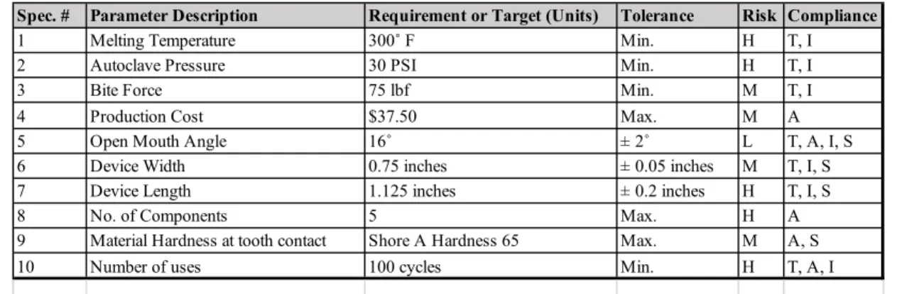
Table 1. Adjustable Bite Block Engineering Specifications. Risks are noted as high (H), medium (M), or low (L). Compliance methods illustrate how each design specification is to be met and
include testing (T), analysis (A), similarity to existing designs (S), or inspection (I).
Sterilization Considerations and Specifications
First, in order to make sure that the device retains its structural integrity through many uses in patients’ mouths and sterilization cycles in the ultrasonic bath and autoclave, the materials used in the development of the device were chosen to have a high strength and high corrosion resistance. There are two main autoclave sterilization processes used in Dr. Ng’s office, and the device is designed to handle many cycles from both processes. The autoclave settings are as specified: 5 minutes at 270˚ F or 30 minutes at 250˚ F. In both cases, the bite block must withstand a pressure of 27 PSI. The ultrasonic bath and autoclave all pose harsh environments to the device, so steps will be taken to ensure that the device retains its shape and structure through a minimum of 100 cycles of routine sterilization procedures.
Ergonomic Considerations and Geometric Requirements
The most important design consideration of the device is patient comfort, and this is ultimately why a new design is being developed. The device is being designed to keep the patient as comfortable as possible throughout the entire duration of their procedure and limit aches and pains that commonly can occur in the subsequent days. In order to quantify patient comfort into measurable values, the following specifications were selected: The device will have a profile designed such that it minimizes the potential trigger of any gag reflexes. Therefore, the device will have a total thickness of no more than 0.75 inches. A final aspect taken into consideration for patient comfort is the contact point between the teeth and the device. In order to disperse the force of the jaw on the bite block, the device will have supporting surface that covers the area from the patient’s first pre-molar to their first molar, and a material with a low hardness will be used for the entire contact surface to create a cushion on which the teeth will rest. Lastly, the bite block will
Spec. # Parameter Description Requirement or Target (Units) Tolerance Risk Compliance
1 Melting Temperature 300˚ F Min. H T, I
2 Autoclave Pressure 30 PSI Min. H T, I
3 Bite Force 75 lbf Min. M T, I
4 Production Cost $37.50 Max. M A
5 Open Mouth Angle 16˚ ± 2˚ L T, A, I, S
6 Device Width 0.75 inches ± 0.05 inches M T, I, S
7 Device Length 1.125 inches ± 0.2 inches H T, I, S
8 No. of Components 5 Max. H A
9 Material Hardness at tooth contact Shore A Hardness 65 Max. M A, S
An additional key factor in the development of the alternative bite block solution is for this device to be easy to use for both the dentist and hygienist. If the device is a complex assembly containing an excessive amount of parts or implementation steps, those performing the procedure would not use the device, rendering it ineffective. Therefore, there Dr. Ng has requested that be no more than 5 separate components when the bite bock is disassembled for sterilization. The design will maintain a low profile so that dental tools may be introduced to and removed from the mouth with minimal impedance from the device.
Structural Requirements and Loading Specifications
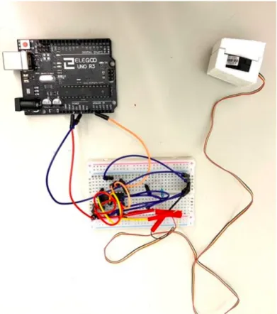
Figure 1. Bite Force Generation Circuit. An Arduino Microcontroller wired to a breadboard containing an INA125P instrumentation amplifier. The top right of the image displays the load
cell surrounded by the 3D printed components mimicking the dimensions of the bite block
Cost Considerations and Requirements
The final factor considered in the adjustable bite block design is cost. Even though there are currently no other bite blocks on the market with a means to adjust to each patient’s individual mouth size, ensuring low material and manufacturing cost is vital to the device’s success in a competitive market. Therefore, the finalized design will have a retail price no greater than $75, with a target market price of 2 times the production cost. This maximum retail cost was determined from discussions with Dr. Ng regarding the amount he felt reasonable for the cost of this adjustable and reusable device. The requirements listed in this section are outlined in Table 1 and further detailed in the QFD (Appendix A).
Project Management
simulations, and documenting the project by taking photos during key testing and manufacturing days that are taking place throughout the project.
Connor, a general engineering student, has taken on the role of leading the testing processes necessary for ensuring our final design will meet all specified engineering requirements, helping create CAD documents, planning manufacturing, and sourcing manufacturing quotes.
Chapter 2: Background
Existing Products
Many options are available on the market at the time this document is being written. PropGard Mouth Prop (Figure 2), Logi Bloc (Figure 3), E-Z Mouth Prop (Figure 4), and Markel Mouth Prop (Figure 5) were listed on dentalcompare.com as the current and most popular bite block options available for use. However, each of these designs possess key limitations that Elevate Dental is addressing in the development of its innovative design.
Existing Product Limitations
The PropGard Mouth Prop by Ultradent Products, Inc. (Figure 2) is not autoclave-safe, and it features only two different sizes: regular and large. This design also blocks the direct access of suction and other dental tools from the bite block area due to its vented walls.
Figure 2. PropGard Mouth Prop from Ultradent Products, Inc.
Figure 3. Logi Bloc from Common Sense Dental Products, Inc.
The E-Z Mouth Prop by Dentsply Sirona Preventative (Figure 4) is interesting because it is marketed as a disposable product with a Styrofoam construction that can conform to the patients mouth, but it is quite large and directly blocks all access of suction from the side of the mouth where it is placed.
Figure 4. E-Z Mouth Prop from Dentsply Sirona Preventative
Lastly, the Markel Mouth Prop, by Hu-Friedy Manufacturing Company, Inc. (Figure 5), is a similar design to the PropGard but is autoclave-safe.
Figure 5. Markel Mouth Prop from Hu-Friedy Manufacturing Company, Inc.
There is a direct need for a bite block that incorporates the best features of each design and is adjustable in order to accommodate the largest possible patient population. Elevate Dental seeks to create the design that successfully meets these needs.
Chapter 3: Initial Design Development
Ideation Process
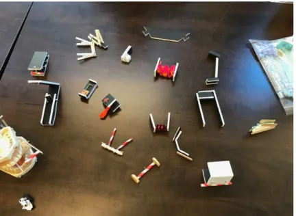
Figure 6. Physical Models Generated from Prototyping Session
We began the ideation process by conducting brainstorming sessions to generate numerous design ideas (Figure 6). After the initial brainstorming meetings, we prototyped our designs using foam board and household materials to develop physical models of our initial designs.
Final Design Concepts
After developing dozens of potential design concepts during prototyping sessions in class, we were able to refine the list to four designs that conformed best to the customer requirements and engineering specifications. The general mechanisms of the designs are as follows: Multiple attachment kit, fully threaded shaft, set screw shaft, and zip-tie. Each design is discussed in detail in the following sections.
Multiple Attachment Kit
Figure 7. Interchangeable center shaft kit bite block concept
While this design would be simple to use and could provide for greater adjustability than current models if the number of shafts provided exceeded the number of available Logi Bloc sizes, the design has several limitations. The first limitation relates to the projected manufacturing cost. Developing a kit with many different sized shafts would be much more expensive to manufacture than a device containing a single mechanism for adjustment due to the number of molds needed. Furthermore, the kit would contain many small parts that could easily be lost and could become tedious for both dentist and hygienist to assemble and disassemble. The second issue relates to sterilization. If the dental staff were to incorrectly select certain sized shaft for a patient’s mouth, they would need to sterilize that shaft as well as the properly sized shaft. This would lead to an excess amount of parts that would require sterilization and could be viewed as an inconvenience by the dentist.
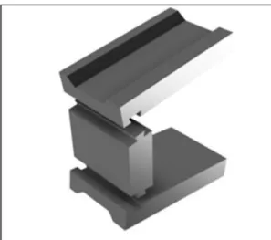
Fully Threaded Shaft
The second preliminary design we considered during our design refinement stage involves the use of a threaded central shaft and a threaded outer tube (Figure 8). The mechanism of adjustability comes from the two components interacting. As the two components are twisted together, the distance between the two wings decreases. This concept allows for a substantial increase in flexibility when compared with the kit design, as the thread pitch would most likely offer more room for adjustment. Furthermore, this design would only contain two parts as opposed to the 7 or more that the kit would need to include to be a viable option. Finally, twisting the threaded components for adjustment is an intuitive process.
Figure 8. Fully threaded bite block concept
Although the fully threaded design contains many positives in comparison to the multiple attachments kit, there are several limitations to this design that led us to pursue other concepts. With this design, there is no means for adjusting the bite block inside the mouth. The adjustment mechanism requires the rotation of one or both of the wings to create a smaller or larger distance between them, and this rotation is not possible inside the patient’s mouth. Additionally, there is no locking mechanism to keep the two shafts in place. This could be problematic for retaining mouth stability during the procedure. Another issue with this design is the torque that would result from a patient biting on the block. Due to the angle of the threads, a human biting force would cause the shaft to rotate which could severely injure the patient. Finally, in order to make sure that the threads withstand the requirement of 100 uses, we believe that they will be manufactured out of metal. As a result, this would lead to an increase in the overall cost of the product.
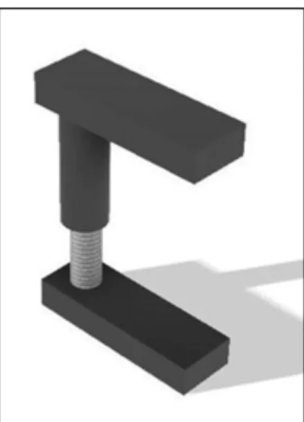
Set Screw Shaft
Figure 9. Set screw bite block concept
Although this design provides a cheaper and more stable means of adjustment when compared to the previous two designs, there are still several issues with its usability. First, depending on the strength of the bite block, the internal shaft might require a metal composition. The constant interaction of a metal screw could cause damage to a plastic central shaft leading to a direct reduction in the lifespan of the device. In addition, the screw itself poses several limitations. First, because the screw is a small, freestanding part in the mouth, it could easily be considered a potential choking hazard. Furthermore, the set screw design requires an additional tool in order to be adjusted. If this were included with our product, this would lead to an increase in the overall cost of the system. This tool would also need to be sterilized in between each procedure along with the components of the bite block which could be an inconvenience to the dentist.
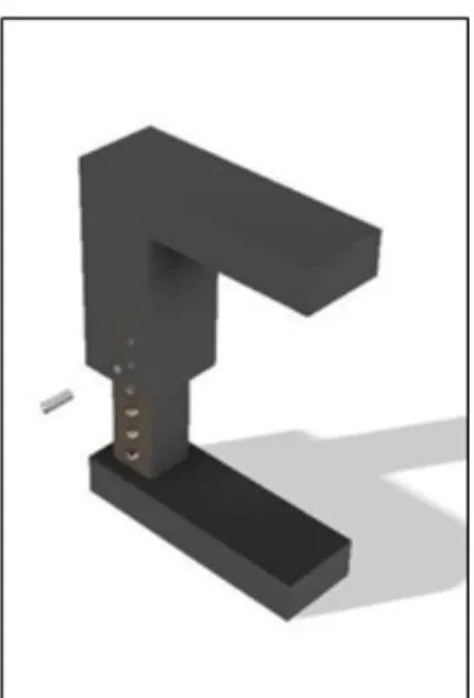
Zip Tie
Figure 10. Zip Tie Bite Block Concept
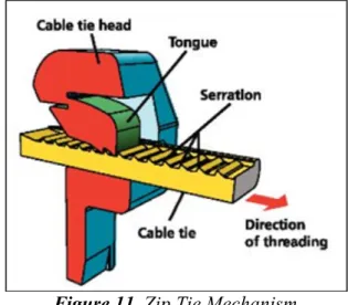
The general concept of the zip tie bite block design (Figure 10) utilizes the fact that zip ties are extremely strong in tension due to the interaction between the internal cable serrations and the tab serrations. This design flips the orientation of the serrations on both the tab and the internal shaft so that the design is strong in compression as opposed to tension. It should be noted that while the tooth orientation is being modified to resist exterior compression rather than tension, the loading condition on the tab in our design will still be similar to the traditional zip tie tab mechanism.
Figure 11. Zip Tie Mechanism
Concept Selection
Table 2. Pugh Matrix Comparing Final Four Design Concepts.
Our top concept was selected from the pool of concepts due to how it performed in a Pugh matrix analysis (Table 2) which provides a visual representation of the advantages and limitations of our four final design concepts. The zip tie design was used as the datum and other concepts were compared to it in the matrix. The other designs all had fewer pluses than minuses when compared to the zip tie, which led to the zip tie design being chosen. In almost all categories, such as adjustability, ease of use, and affordability, the zip tie design was found to be equal to or better than the other concepts. It should be noted that we chose the zip tie design as our datum in the Pugh Matrix because the current bite block used by Dr. Ng isn’t adjustable. Because adjustability is the essential reason for pursuing this project, it wouldn’t have made sense for the adjustable alternatives to be compared against a nonadjustable bite block.
retain its structure in the autoclave. Polypropylene can also be glass fiber reinforced to improve its strength if necessary. Therefore, the necessary steps and analyses were taken to ensure that the designed model is conducive for polypropylene as the final material.
Chapter 4: Detailed Design Development
Refined Design Description
Over the course of winter quarter, the zip tie design was further developed by making important modifications for the injection molding manufacturing process, performing load cell bite force tests, making SLA prototypes to further assess ergonomics and the tab mechanism functionality, and conducting preliminary finite element analysis.
Our initial detailed concept (Figure 12 and Figure 13) utilizes a zip-tie mechanism for adjustability. The head of a zip tie consists of a serrated tab attached via a living hinge to an outer housing that has a small opening in it for the cable to pass through. The zip tie cable has teeth on it that fit together with the teeth on the tab. As the cable is pulled through the head, the teeth on the tongue engage with the teeth on the cable. If you try to pull the cable back out of the head, the flat faces of the teeth on the cable put pressure on the flat faces of the teeth on the tongue. This creates a force on the tongue that both pushes it down, to be supported by the head, and pushes it into the cable itself, pinching the cable between the tongue and the opposite side of the head. These forces make a zip tie very strong once the mechanism is engaged. Our concept inverts this design to make the bite block strong in compression and adjustable in tension. This will allow for resistance when being bitten down on and allow for easy adjustability when not experiencing a compressive load.
Preliminary Bite Block Finite Element Analysis
Figure 14. First iteration bite block when experiencing the maximum loading at the largest setting. This image highlights the high bending stress that develops in the center column.
(Results shown in psi.)
Figure 15. First iteration bite block when experiencing max loading at the largest setting. This image highlights the stress concentrations that develop at the sharp points of contact between
Figure 16. First iteration bite block when experiencing max loading at the second smallest setting. The stresses for this setting are lower than the maximum setting shown previously.
(Results shown in psi.)
For the above simulations, the stress values were far above our allowable max yield stress, so we made sure to make geometric modifications to the critical stress locations. Furthermore, we spent time understanding the intricacies of the Abaqus software to ensure that our bite block loads and boundary conditions were fully correct. We also researched finite element analysis meshing techniques to further ensure our mesh fully and accurately captures the bite block geometry.
Finite Element Analysis – First Iteration Design Changes
From our first iteration of FEA, we learned that we needed to modify the design to reduce the stress concentrations that develop at the points of contact by adding fillets to the contacting edges. Additionally, we strengthened the center column by increasing its cross sectional area to increase the moment of inertia.
with the new material property information shown in Table 3 for general purpose polypropylene, we ran FEA simulations with a prescribed vertical displacement of .05 inches on the tab to simulate a person pressing down on the tab with their figure. This deflection would approximately be the amount needed to disengage the bite block teeth and allow for free adjustment of the bite block height settings.
Table 3. Polypropylene general purpose material property data. (English units)
The first trial for this analysis was based on a coarse mesh with 24,978 elements. This allowed us to gain initial results and ensure that the simulation would converge with the specified boundary conditions and material properties. Figure 17 captures these results. While these stresses are larger than the maximum yield strength, it was possible that the coarse mesh was resulting in unrealistic stress values.
Figure 17. General purpose polypropylene bending tab mechanism deflection analysis. (24,978 elements) (Results shown in psi.)
We modified the tab’s mesh and increased the element count to 198,433 to gain more refined results. Unfortunately, this new model resulted in higher stresses and indicated that there was likely a problem with the tab mechanism design. As noted in Table 3 the maximum yield stress of general purpose polypropylene is 4580 psi.
Property Value Units
Elastic Modulus 248000psi Poisson's Ratio 0.43unitless Max Yield Strength 4580psi
Figure 18. General purpose polypropylene bending tab mechanism deflection analysis. (198,433 elements) (Results shown in psi.)
Figure 19. General purpose polypropylene bending tab mechanism deflection analysis with modified contour plot to highlight all nodes that exceed the maximum yield strength of the
material. (198,433 elements) (Results shown in psi.)
Table 4. Polypropylene 40% GF material property data (English units)
Figure 20. Polypropylene 40% GF bending tab mechanism deflection analysis. (198,433 elements) (Results shown in psi.)
Figure 21. Polypropylene 40% GF bending tab mechanism deflection analysis with modified contour plot to highlight all nodes that exceed the maximum yield strength of the material.
Property Value Units
Flexural Modulus 943000 psi Poisson's Ratio 0.33 unitless Max Flexural Strength 19580 psi
strength to the maximum stress shown does not change much as well. For this particular geometry, changing the material does not provide a significant positive improvement to the stresses.
Alternate Tab Mechanism Design
We took a closer look at adjustable zip tie mechanisms currently available on the market (Figure 22) and found that these tabs are actually anchored to the main structure on the tab’s sides rather than the base of the tab. This results in stresses developed from torsional loading rather than a bending moment.
Figure 22. Adjustable Zip Tie
Figure 23. General purpose polypropylene torsional tab mechanism deflection analysis. (154,036 elements) (Results shown in psi.)
Figure 24. General purpose polypropylene bending tab mechanism deflection analysis with modified contour plot to highlight all nodes that exceed the maximum yield strength of the
material. (154,036 elements) (Results shown in psi.)
Figure 25. Polypropylene 40% GF bending tab mechanism deflection analysis with modified contour plot to highlight all nodes that exceed the maximum yield strength of the material.
(154,036 elements) (Results shown in psi.)
Tab Mechanism Removal
As a result of all the information gained from our previous finite element analyses, we needed to make a significant design modification for the bite block to withstand its numerous loading conditions. We initially believed this tab mechanism would be critical for the adjustment of our design, but after further consideration, we were able to remove the tab and maintain the zip tie mechanism functionality by removing one of the bite block’s side walls. This removes the need to deflect a tab for any adjustment purposes because it allows the inside bite block to be inserted into the outside bite block from the side rather than the top (which is why we needed the tab in the first place). Additionally, this allowed us to increase the width of the center column, thus increasing the contacting surface area between the inner and outer block’s mating teeth and creating a stronger and more rigid center column that would better withstand the bending moment induced from a large bite force.
The one drawback with this design is that, in theory, the bite block could potentially slide out from the side. However, after consulting Dr. Ng, we believe this open faced design will not be an issue because the bite block undergoes loading from a person’s teeth in the same plane of the bite block. Furthermore, tight tolerances between the teeth and friction would prevent sideways movements under a compressive load.
that the load was applied as pressure load defined by the maximum force in Abaqus on the top surface, and the bottom surface was fixed using an encastre boundary condition.
Table 5. Polypropylene 40% GF material property data. (metric units)
Figure 26. Polypropylene 40% GF bite block assembly FEA results for a 330 N bite force load. (Results shown in MPa.)
When looking at Figure 26, we see that the maximum stress slightly exceeds the flexural strength of the material. However by using a cross section analysis, we were able to find where this maximum stress is occurring. (See Figure 27).
Property Value Units
Flexural Modulus 6500 Mpa
Poisson's Ratio 0.33 unitless
Max Flexural Strength 135 psi
Figure 27. Polypropylene 40% GF bite block assembly FEA results for a 330 N bite force load. A cross section analysis was used to highlight the region of maximum stress (Results shown in
MPa.)
As shown in Figure 27, the maximum stress on the bite block occurs at the small fillet at the base of the flexible internal hinge, so another cross section analysis was used to take a closer look at the stresses on the bite block’s teeth. (See Figure 28).
stress. Unfortunately, the same settings that were used in our previous assembly’s FEA were not adequate for obtaining convergence with our new design, so we believe that further analysis should be performed to ensure that this device in fact withstands the maximum loading conditions. Modifications will most likely need to be made to fine tune each block’s mesh topology. Additionally, the contact interaction between both blocks may need to be redefined in a new way to obtain convergence.
Chapter 5: Description of the Final Design
Figure 29. Final bite block design rendering.
Final Design Overview
The final design gets rid of the previous design’s tab in favor of fixed teeth. The inner block slides into the outer block in any one of 5 height positions. The bite block maintains a comfortable open mouth angle (16°) while allowing for easy dental tool access by virtue of the U-shaped cutout between the two bite surfaces. Both bite surfaces are lined with bite pads that provide a soft bite surface for patient comfort.
them stronger and prevent breaking. Molded hash marks on the side of the block allow for easy sizing of the bite block. Dr. Ng requested this feature as a way to easily keep track of a patient’s size in their dental records so that the block can be adjusted properly before ever entering their mouth.
The faces of the block that a patient’s teeth will contact have a 16° angle between them which keeps the mouth open in a comfortable position. This angle is maintained at all adjustment positions. Additionally, these faces have a channel down the middle that is designed to fit a patient’s first molar, second premolar, and first premolar. A santoprene bite pad that is 1.30 mm thick will be over-molded into the channel on both blocks so that patients have a soft, comfortable surface to rest their teeth on.
Figure 30. Final bite block design exploded view rendering.
Material, Geometry, and Component Selection
The bite block will be made of two materials, both of which are appropriate for their respective roles and are available for injection molding from ICOMold. The two blocks will be molded from a 40% glass fiber reinforced polypropylene (Kingfa GFPP-40 NC001)3. This material was chosen
car tire tread. This hardness will allow some padding for comfort while maintaining structural stability and toughness.
Because the materials of the bite blocks and bite pads both contain polypropylene, they can be effectively over-molded for a strong chemical bond. This will ensure that the bite pad and block never delaminate during use or sterilization. Delamination could result in bacterial buildup within the region between the polypropylene and santoprene which could potentially lead to an unsanitary bite block even after sterilization.
The geometry of the bite block has been carefully selected to maintain dentist and patient comfort, structural stability, and manufacturability. It is important to maintain a consistent angle of 16° at all sizes of adjustment. The bite block was designed with a constant angle of 8° between each bite pad and center column so that the only geometry change during an adjustment of the block is in the length of the center section which results in a comfort that is consistent for all patients. Dr. Ng wants the bite block to adjust from the child size Logibloc to slightly larger than the adult Logibloc. The child Logibloc measures 26mm at the opening, and the adult size measures 29.5 mm. Our bite block was designed to have an opening of 26 mm at the lowest setting (Appendix B.4) and 32.9 mm at the highest setting (Appendix B.5). There are 1.5 mm between each size, which allows for five sizes. The dimensions of the channels where a patient’s teeth will sit are 27 mm long and 12 mm wide, which is consistent with the adult Logibloc. Dr. Ng finds this tooth channel to be comfortable for all of his patients. The maximum length and width of the bite block are 27mm, and 18mm, respectively. These dimensions are as minimal as we determined they could be made without compromising the structural stability of the bite block. This also benefits the patient by keeping them from having anything too bulky in their mouth and benefits dentists and dental assistants by taking up as little mouth real estate as possible allowing for unencumbered access to patients’ mouths. The final dimensions also take into account necessary design characteristics for easy injection molding. Relatively uniform wall thickness throughout the parts will be utilized to minimize shrinkage and warping of the parts as they cool after molding (Appendix B.1 & B.2). When injection molding starts, the design will have to be modified slightly to add whatever draft angle the injection molding company desires on the faces it requires. This cannot be done yet because companies have different requirements and often won’t reveal them until money is paid for molds.
Safety Considerations
Our team holds the safety, health, and welfare of our customers to be paramount in the success of creating a device that can be placed on the market. The device will be constructed to be as intuitive to use as possible, removing any requirements of additional labeling or training in ensuring the safety of the patient.
The locking mechanism of the bite block needs to be able to sustain a compressive load for extended periods while a dental procedure is taking place which can be achieved by choosing the material and dimensions of the device to match the potential load being sustained, so that it is as strong as possible without interfering with the function.
Maintenance Considerations
The bite block should be taken apart and sterilized in an ultrasonic bath and autoclave after each use. This is standard dental procedure, but we thought it was worth noting.
Chapter 6: Product Realization
Additional FEA
Unfortunately, we were not able to get FEA for the new design to work. Further iteration on FEA settings for this design will be necessary to ensure that the bite block should be strong enough for use. While FEA is a good tool for analyzing the stresses a part will experience under load, it is not always completely accurate. Therefore, it is necessary to move on to physical testing after verifying positive results in FEA.
Prototyping via 3D Printing
Table 6. Comparison Between FormLabs Durable Resin and General Purpose Polypropylene
The only SLA print we were able to create was one of the old zip tie design. Unfortunately, our living hinge proved to be difficult to print at a strength equivalent to an injection molded part, meaning it was too weak to be tested. The rest of the structure was much more solid and analogous to an injection molded part. Because the new design eliminates the flexible tab that caused problems in our previous SLA prototype, we believe it will be much more suitable for testing than the previous design. It is still important to note, however, that the material properties of the durable resin will be different enough from injection molded glass filled polypropylene that discouraging results in testing the SLA prototypes should not necessarily be seen as showing the design to be ineffective. If the design passes the requirement of not breaking under a 75 lbf force, and SLA prototypes at least pass the comfort and ease of use test described in Chapter 7, it is reasonable to move on to injection molded prototyping.
Prototyping via Injection Molding
After the design has been verified by FEA and testing of SLA prototypes, injection molded prototypes should be produced to test. There will be one mold for the bite blocks that is injected with glass-filled polypropylene, and another mold for the bite pads. Because the bite block pieces are similarly sized, both molds can be cut into a single piece of steel, effectively eliminating the need for two separate molds (one for each bite block piece). This reduces both mold and part cost significantly. The same goes for the bite pads. Both bite pad molds will be cut into the same mold. The bite pads will be adhered to the blocks during production in a process called over-molding. After the blocks are molded and cooling in the mold, the bite pads’ mold is placed on top of the blocks’ mold. The over-mold will inject new material, santoprene, onto the parts in the shape of the bite pads. Because this process is done before the bite blocks cool completely, the polypropylene of the blocks and santoprene of the pads will chemically bond, resulting in a bite block-pad assembly that is effectively one part. This will prevent the two from becoming separated during use or sterilization.
The company we recommend for all of the injection molding required for the project is ICO Mold. They have the capability to produce extremely tight tolerances with their molds, and are cheaper than other companies we received quotes from. They also provide the materials chosen for the bite block, and these costs are included in the per-part cost, making raw material sourcing unnecessary. Once the design has been determined to be ready for prototyping with injection molding, ICO Mold should be given CAD files for each part in the design as well as assemblies of the whole bite block and each bite block and its requisite bite pad. They should also be given engineering
Property FormLabs Durable Resin Polypropylene Tensile Strength (MPa) 31.8 25-40
Tensile Modulus (GPa) 1.26 1-1.5
Elongation (%) 49 100-400
the designed has been cleared for molding, ICO Mold will cut the molds and provide a small quantity of sample parts for approval. If the parts are of satisfactory quality, the second 50% of the mold costs and the desired quantity of prototype parts must be paid for. Once ICO Mold has received this payment, they will ship out the desired quantity of prototype parts, These parts should be tested according to the tests outlined in the “Recommended Physical Testing” section of this report. If the parts fail testing, the design will need to be reworked and new molds will need to be made for retesting and production.
The quoted cost for molds and 100 complete bite blocks from ICO Mold is $13,704, and the cost per part is $137.04. While these prices are high, it is important to realize that molds are expensive to create and ordering a higher quantity of parts will greatly reduce the cost. This will be shown in the production section. Additionally, the more parts ordered, the less ICO Mold charges per part (not including molds cost.) After the first production run, every additional order will include a $150 setup cost, regardless of part quantity.
Production: Injection Molding
If the prototype parts pass the required tests and Dr. Ng is happy with their function, then a larger quantity of parts can be ordered. If 2500 complete bite blocks are ordered, the total cost per bite block, including the mold cost, will be $7.06 according to our quotes (including the $150 setup cost). ICO Mold supplies lifetime molds, which means that they will continue to make new molds for you as necessary as long as you want parts produced. This means that it will never be necessary to pay for new molds because worn out molds will be replaced for free, so the more bite blocks that are produced the cheaper they will become when the cost of the molds is factored in.
Overall Cost Breakdown
The cost estimate for the bite block consists of three parts: 3D printing prototyping, injection molding prototyping, and injection molding production.
3D printing prototyping costs for the bite block were relatively minimal. A roll of TPU filament for preliminary FDM prototypes cost $45. For SLA printing, we used Formlabs durable resin, which cost $175 for one liter. One liter of resin should be enough for all prototypes moving forward. We also needed to buy a build platform for the SLA printer that cost $100. In total, our prototyping costs are roughly $350 after shipping and taxes are factored in.
Provided that one set of molds are cut, and a prototype run of 100 bite blocks is made, followed by a production run of 2500 bite blocks, the total cost will be $18,304. Assuming that the 100 prototype bite blocks are not sold, each sellable bite block will have an effective cost of $7.32.
Chapter 7: Design Verification
Testing
This document outlines the necessary tests that each bite block concept must pass in order to be considered for implementation. It is recommended that these tests (excluding the autoclave test) are first attempted with SLA 3D prints made from Formlabs durable resin because its material properties are the closest to polypropylene of any consumer 3D printing resin. It is important to note, however, that the material properties of the printed pieces may still vary greatly from those of an injection molded bite block. For best results, it is recommended that the model is sliced in a 3D printing software package and printed in a specific orientation for the test comfort and compression tests. The bite block should be printed so that it is sliced along its lateral (side view) axis. This should give the teeth and tab the most structural integrity possible from a 3D print. It is highly recommended that injection molded parts are ultimately tested with each of the protocols outlined below. These tests are comprehensive and are the best estimate of ensuring that the bite block will not fail during use. It is important that the same final bite block design passes all of the tests listed below. Any change in design must result in retesting of the final product in every test outlined below. The compression and autoclave tests should be performed on a minimum of 30 injection molded bite blocks, which is the minimum number of samples required to approximate a normal distribution of material properties and part strength. It is also important to note that adding pigment to the injection molded parts may change their material properties. The way that the pigment affects the properties can be inconsistent, so it is important to test the bite block in all colors it will be produced in.
For each subsequent design, the testing sequence must be repeated. To ensure consistency in the testing process, tests involving SLA 3D printed prototypes should be completed in the following order (details for each specific test are outlined below):
1. Comfort and Ease of Use 2. Compression Testing
This sequence does not include autoclave tests, which are vital for the success of the final bite block product. However, the Formlabs durable resin does not maintain structural integrity when subject to autoclave conditions. Thus, finalized injection molded models should have an additional autoclave step added to the testing sequence to result in the following:
Test 1 – Comfort and Overall Ease of Use
This is a purely subjective test that Dr. Ng and his employees will carry out in their office. Each person will put a bite block in their mouth for a test fit, and then remove it to adjust it to the proper size. Each person should determine if they can find a size that gives them a comfortably (wide) open mouth, and whether or not the bite block is comfortable in their mouth. Dr. Ng and his assistants should also pay attention to the bite block’s ease of use.
Test 1 – Specific Test Setup Details
For the sterilization purposes, either each person who will test the bite block should get their own, or the bite block should be covered in a new, sterile, nitrile glove before being placed in each mouth. When doing this test with a 3D printed part, a layer of material equal to the thickness (1.36mm) of the santoprene bite pad should be added to each bite face. This will maintain the geometry and sizing that the bite block was designed for. It is important to realize that a lack of santoprene bite pad will make the bite surface much harder and more uncomfortable to bite than the injection molded piece will be, and this should be taken into consideration when analyzing comfort.
Test 1 – Criteria for Passing:
If 90% of the testers in Dr. Ng’s office feel that the bite block can be adjusted to a comfortable position, is comfortable within the mouth, and is easy to use, then the bite block passes the test. If less than 90% of the testers feel that any of these criteria is not met, the bite block fails.
Test 2 – Compression
Test 2 – Specific Test Setup Details
When assembled in the Instron tester, the bottom bite pad should be fixtured to the machine, and the top bite pad should receive a distributed force perpendicular to its face. Solid 3D printed fixtures should be generated and mounted to both the top and bottom plate of the Instron. The fixtures should be wedge-shaped and should mimic the dimensions of the internal bite pad. Furthermore, the angle of each fixture should be approximately 8 degrees. Therefore, when the bite block prototype is mounted, the force will be distributed along the axis of the bite block column. This will mimic the direction of the force that the bite block feels when a patient bites down on it. A total of 3 compressive tests must be performed to verify that the bite block remains structural integrity in all possible positions
As the bite block adjusts through its height range, the stress distribution that it experiences under a compression load changes. This means that different areas of the bite block will receive different stresses when it is at different heights. Thus, it is necessary to test the bite block at each height setting to ensure it will not break under the different stresses encountered at each height. To allow for this, compressive tests should be performed with the bite block at its maximum height setting, minimum height setting, and middle setting. Two settings should receive 67 compressions, and one should receive 66.
Test 2 – Criteria for Passing
In order to pass this test, the bite block must withstand 200 cycles of a 75-pound load in the Instron without breaking or the alignment rib popping out of its slot. If the alignment rib pops out of its slot or the bite block breaks during any of the trials, the bite block has failed the test.
Figure 31. Compressive Test Example.
Test 3 – Autoclave
ensure that the increased temperature of the former does not increase warping due to increased thermal stress. This test ensures that the bite block is not so degraded by the autoclave that it will either break or deform to the point that it can’t be used at any point during its lifespan. Particular attention should be payed to any deformation of the teeth and tab throughout this test. Excessive deformation is cause for concern and a potential redesign. Additionally, note whether or not the santoprene bite pads delaminate from either piece during this test, as any crevices between the block and pad can lead to potentially unsanitary conditions.
Test 3 – Specific Setup Details
Refer to the fatigue and compression testing sections above for those portions of this test. When placing the pieces in an autoclave bag, be careful that the parts aren’t touching to allow the steam to contact all surfaces of each piece. This will ensure complete sanitation.
Test 3 – Criteria for Passing
If the bite block passes all 300 adjustments, 200 loadings, and 100 autoclave cycles without breaking or deforming beyond use then it has passed this test. If the block breaks, deforms beyond use, or the bite pads delaminate from the block the bite block fails. If it passes this test, the bite block can be considered strong enough for use in patient’s mouths for a life cycle of 100 uses.
Design Verification Checklist
The current bite block design meets all but three requirements set in Table 1. The three requirements not yet definitively met are the minimum pressure to survive the autoclave (30 psi) he strength required to survive a maximum bite force of 75lbf (334 N), and the minimum number of uses (100). By virtue of the materials we have chosen for the bite block, and the way we have joined the bite pads to the blocks, we do not expect there to be issues with the bite block surviving the autoclave. Both polypropylene and santoprene are known to be able to withstand autoclave cycles. We feel that it is still important to verify the requirement of autoclave survivability via testing. Based on FEA of the previous design, which showed a factor of safety of 1.7 on the teeth (Figure 28), we believe that the bite block is strong enough to withstand the maximum bite force (75lbf) that it may see in use, but again, we feel that it is important to test this as outlined in Chapter 7. The autoclave test in Chapter 7 should show that the bite block can survive the autoclave and multiple maximum compressions per use for the bite block’s lifespan of 100 uses. This test is crucial to verify the design.
separable components, which was Dr. Ng’s most desired number, even though he was ok with up to five. At tooth contact, the santoprene has a Shore A hardness of 53, which is under our maximum allowable hardness of 65.
Upon further FEA analysis and physical testing, it is expected that the bite block design will meet all requirements specified in Table 1.
Chapter 7: Conclusions and Recommendations
At the time of the submission of this report, a promising concept for the side loading adjustable bite block has been developed. However, there are several key factors that must be addressed before the design can be finalized and approved for production injection molding. First, finite element analyses of the bite block under a 75lbf compressive load is necessary. This will help to ensure that the design is worth prototyping. Because we have removed the adjustment tab and increased the size of the teeth, we believe that the new design will prove satisfactory in FEA, but unfortunately we have not been successful running FEA on this design. Upon completion of FEA with satisfactory results, SLA 3D printed prototypes should be developed and tested. If testing with SLA 3D prints is successful, prototyping and testing should be done with injection molding to produce parts that are completely analogous to production bite blocks. Once injection molded prototypes have passed all tests listed in Chapter 7, the bite block is ready for production.
The design presented in this report should not be considered the final design for the adjustable bite block and is subject to modifications. Though the side loading bite block design seems to withstand our engineering requirements for loading, further iteration via FEA, prototyping via SLA 3D printing and injection molding, and testing are necessary for the ultimate development of a finalized adjustable bite block design provided by Elevate Dental and Dr. Ng.
Chapter 8: Acknowledgements
We would like to express our sincere appreciation to our advisor, Professor Karla Carichner of the Materials Engineering Department as well as our Sponsor, Dr. Douglas Ng, DDS for providing us with the opportunity to embark on this project and for all of their help and guidance along the way. Additionally, we would like to thank Dr. Sthanu Mahadev and Professor Jonathon Stearns of the Mechanical Engineering Department for their additional assistance and guidance with the finite element analysis portion of the project.
Chapter 9: References
1. “Bite Blocks.” Dentalcompare, www.dentalcompare.com/Restorative-Dentistry/4696-Bite-Blocks/.
2. Takaki, Patricia et al. “Maximum bite force analysis in different age
groups.” International archives of otorhinolaryngology vol. 18,3 (2014): 272-6. doi:10.1055/s-0034-1374647
3. GFPP 40; Online; Kingfa Sci. & Tech. Co., Ltd.: Guangzhou, China, November 11th, 2016. https://materials.ulprospector.com/en/profile/odm?tds&docid=213451 (accessed 5/13/20).
4. Santoprene 8211-55B100; Online; ExxonMobil: Houston, Texas, June 20th, 2014. https://exxonmobilchemical.ides.com/enUS/ds244555/Santoprene%E2%84%A2%20821 1-55B100.aspx?I=74710&U=0 (accessed 5/13/20).
5. “Accelerated Aging Test & Accelerated Life Cycle Testing.” Priorclave, Priorclave North America, 29 May 2020,
www.priorclave.com/en-us/autoclave-customers/accelerated-aging/.
6. Houshyar, S., Shanks, R. A., & Hodzic, A. (2009). Modelling of polypropylene fibre-matrix composites using finite element analysis. Express Polymer Letters, 3(1), 2–12. doi: 10.3144/expresspolymlett.2009.2
7. “Cambridge 8 in. Releasable Cable Ties, Black (20-Pack)-CT12796.” The Home Depot, www.homedepot.com/p/Cambridge-8-in-Releasable-Cable-Ties-Black-20-Pack- CT12796/303059758?mtc=Shopping-VF-F_D27E-G-D27E- 27_11_TOOLS_And_ACCESSORIES-MULTI-NA-Feed-PLA-NA-NA- TOOLS_ACCESSORIES&cm_mmc=Shopping-VF-F_D27E-G-D27E- 27_11_TOOLS_And_ACCESSORIES-MULTI-NA-Feed-PLA-NA-NA- TOOLS_ACCESSORIES-71700000033101173-58700003868916496- 92700048703499430&gclid=Cj0KCQjwlN32BRCCARIsADZ-J4vOa7728rmfmGfF0yzLeKoU5DX0gW5SY8AyG9TIG0yg7nVlwgj70FoaAiEeEALw_ wcB&gclsrc=aw.ds.
Appendices
• Appendix A: Quality Function Development Table
• Appendix B: Final Drawings
• Appendix C: List of Vendors, Contact Information, and Pricing
• Appendix D: Vendor Supplied Component Specifications and Data Sheets
• Appendix E: Updated Gantt Chart
• Appendix F: Hazard Identification Checklist
Appendix B: Final Drawings
Appendix B.4: Bite Block Collapsed Section View
Appendix C: Vendor Contact information and
Manufacturing Costs
Appendix C.1 Vendor Contact Information
ICO Mold, LLC 6415 Angola Road Holland, OH 43528 [email protected]
(419) 867-3900
Appendix C.2 Manufacturing Cost
Table 7. ICOMold Manufacturing Cost
Part Mold Cost Part Cost: 100 Parts Total: Molds + 100 Parts Part Cost: 2500 Parts Total: Molds + 2500 Parts
Bite Blocks $6,129 $361 $6,490 $2,000 $8,129
Bite Pads $6,776 $438 $7,214 $2,600 $9,376
Appendix D: Vendor Supplied Component Specifications
and Data Sheets
Table 8. Material Data Sheets
Material Link to Material Data Sheet
Polypropylene: GFPP-40 NC001 https://materials.ulprospector.com/en/profile/odm?tds&docid=213451
Santoprene: TPV 8211-55B100
Appendix E: Updated Gantt chart
Appendix E.1: Fall Quarter Gantt Chart
Appendix G: Product Guide for User
The following steps are required for the proper use of the Elevate Dental adjustable bite block and should be followed properly for optimal product use.
1. Connect the upper and lower components of the adjustable bite block together from the side. Ensure that the two components have a tight fit before proceeding to step 2
2. Introduce the adjustable bite block to the patient’s mouth. If the patient confirms that the bite block fits comfortably, proceed to step 4. If the patient deems that the bite block size is too small or too large for their comfort, continue to step 3
3. Remove the bite block from the patient’s mouth and detach the upper and lower
components by sliding them apart from the side. The injection molded hash marks on the upper piece allow for visual alignment with the injection molded hash mark on the lower piece. Adjust the size accordingly for each patient’s needs.
4. Reintroduce the bite block to the patient’s mouth at the optimized size, ensuring that the patient is comfortable with the setting
5. Take note on the patient’s chart of the bite block setting (1 being the smallest size and 5 being the largest size).
6. After completion of the procedure, remove the bite block from the patient’s mouth, and detach the two components of the block by sliding apart.