Virtual Lock: A Smartphone Application for Personal
Surveillance Using Camera Sensor Networks
Sangseok Yoon, Hyeongseok Oh, Donghoon Lee, and Songhwai Oh
School of Electrical Engineering and Computer Science |ASRISeoul National University Seoul, Korea
{skywalker,triptych,killerdh,songhwai}@snu.ac.kr
Abstract—This paper presents Virtual Lock, a novel smart-phone application for personal surveillance using camera sensor networks. The proposed system consists of a smartphone and a set of easily deployable wireless camera sensor motes and enables an inexpensive solution to continuous monitoring of one’s surroundings. Once camera sensor motes are deployed, a user can define multiple regions of interest for each camera’s view using a smartphone application. Then the camera sensor network monitors for any changes in the defined regions of interest. If an event is detected, e.g., when a valuable good inside a region of interest is missing, the Virtual Lock system notifies the user via her smartphone. This paper describes the Virtual Lock system and demonstrates the potential of camera sensor networks.
I. INTRODUCTION
Recently, there is a growing interest in camera sensor net-works or smart camera netnet-works. A camera sensor network is a special case of wireless sensor networks (WSNs) with image sensors. The traditional wireless sensor networks use low bandwidth sensors, such as acoustic, vibration, and infrared sensors, for many monitoring applications but the provided sensors cannot provide enough information to understand com-plex, high-level phenomena. This limitation of the traditional wireless sensor networks can be addressed by camera sensor networks with higher bandwidth image sensors. For instance, image sensors can provide new capabilities such as visual verification, object recognition, activity recognition, and in-depth situational awareness. A camera sensor network, as a special case of wireless sensor networks, is an example of cyber-physical systems, interfacing the physical world with the virtual world.
Many interesting applications using camera sensor networks have been proposed. Yan et al. [1] presented an image search engine over a network of iMote2 sensor nodes with image sensor modules. Basharat et al. [2] proposed a structural health monitoring application using intelligent sensor network which consists of nodes with camera sensors and other sensors such as accelerometers. The authors of [3] implemented a situation awareness system based on a camera sensor network. Teixeira et al. [4] implemented a system operating on symbolic information to help elderly people who live alone. He also presented a method to count the number of people in a room [5]. Heath et al. [6] implemented a multi-person tracking system using stereo camera sensor network. They estimated
3D trajectories and fused them using a particle filter to track objects.
A camera sensor network can be used in robotics. Morioka et al. [7] implemented a human following robot with the help of a camera sensor network to estimate the position of robots and a human. Rekleitis et al. [8] proposed a hybrid system of robots and camera sensor networks to solve planning, localization, and mapping problems. They also used a camera sensor network to gather the robot’s various information such as the shape of calibration patterns on robots seen by camera nodes to use as a source of localization and mapping data.
A major application of camera sensor networks is surveil-lance and security. Tim Ellis [9] implemented a multi-view video surveillance system and presented algorithms to detect and track objects moving through an outdoor environment. Prati et al. [10] implemented computer vision algorithms on camera nodes with passive infrared (PIR) sensors to supple-ment algorithms of detecting and tracking humans which can sometimes cause false alarms. By combining PIR sensors with those algorithms, they could avoid false alarms and improve the accuracy of detection and tracking results.
Many different types of camera sensor motes have been developed. Park et al. [11] developed eCam, Rahimi et al. [12] developed Cyclops, Downes et al. [13] developed WiSN, Xbow [14] developed iMote2 with camera board, and Chen et al. [15] developed the CITRIC mote. Comparison of these motes is shown in Table I. We chose to use the CITRIC motes in our research because of its advanced hardware specifications compared to other kinds of motes as shown in Table I.
In this paper, we present a security system called Virtual Lock which watches any changes in the regions of interest through the camera sensor network, and notifies the occur-rences of certain events to the user via her smarthone. The Virtual Lock system connects a user to her surroundings with the help of camera sensor networks. A user can easily control the Virtual Lock system through her own smartphone and supervise the security status whenever she wants because the Virtual Lock system smoothly combines a camera sensor network with a smartphone application, so, if a certain event occurs, the system immediately notifies the user. Because the Virtual Lock system is very easy to use for anyone who has a smartphone, we expect this system to be a very useful security system.
We also implemented our idea, using CITRIC motes and an iPad, tested the performance of our system, and showed that it reliably worked as we designed. Through the several times of demonstration, we also proved the usability of our Virtual Lock system.
II. SYSTEMOVERVIEW
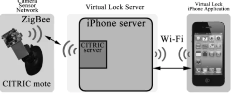
The Virtual Lock system consists of three major components as shown in Figure 1.
The first part is CITRIC motes which form a camera sensor network to monitor regions of interest. Each CITRIC mote contains a 1.3 mega pixel color image sensor and connected to each other wirelessly through IEEE 802.15.4 (ZigBee).
The second part is the server which connects a CITRIC mote based camera sensor network and a smartphone. The server has two parts: the CITRIC server for communicating with the camera sensor network and the iPhone server for the user’s smartphone. The CITRIC server is implemented in C while the iPhone server is implemented in JAVA. We designed the server programs as mentioned above in order to communicate with CITRIC motes and iPhone simultaneously.
As a result, those two main parts, the first and second parts are flexibly connected through the CITRIC server and the iPhone server and work as a whole Virtual Lock system.
The last part of the Virtual Lock system is the iPhone application. The iPhone application provides the user with a graphical user interface (GUI) to control the entire Virtual Lock system. The user can assign regions of interests for the Virtual Lock system to watch, an event to detect during the operation, the period of checking whether the event has occurred or not, sensitivity of the event detection, and an appropriate ignorance level of the event detection to suppress false alarms.
Fig. 1. An overview of the Virtual Lock system.
A. CITRIC motes
There are many types of sensor motes (e.g., eCAM, Cy-clops, WiSN, WiCa, iMote2 with camera board and MeshEye) which can constitute camera sensor networks, however we use the CITRIC mote [15]. The CITRIC mote has better hardware specifications than former motes. The comparison of those motes are shown in Table I. As shown in Table I, the CITRIC mote has the most powerful computational resources, enough amount of memories, and a high quality image sensor. We
(a) (b)
Fig. 2. (a) CITRIC mote. (b) CITRIC mote with TelosB for wireless communication.
have decided to use the CITRIC motes as the nodes for our camera sensor network.
Because of the advanced hardware specifications, we can run various image processing or computer vision algorithms on CITRIC mote discussed in computer vision fields, such as Speeded Up Robust Features (SURF) [16] and Histograms of Oriented Gradients (HOG) [17]. These feature descriptors can be used as event detection algorithms in our Virtual Lock system. The CITRIC mote has 64 MB of RAM and 16 MB of ROM which are enough to save more than 1000 grayscale images with resolution of 320×240. Because the CITRIC mote does not have a communication module, TelosB is attached to a CITRIC mote for communication (see Figure 2(b)). The TelosB has a ZigBee module which is a low-power communication standard based on IEEE 802.15.4 with a maximum bandwidth of 250 kbps.
B. Virtual Lock Server
As shown in the system overview two server programs are running simultaneously to communicate with CITRIC motes and the user’s iPhone. Those two server programs transfer data and commands through socket communication which is fast and reliable. The iPhone server (for iPhone application) runs CITRIC server (for CITRIC motes) as a system call, and starts working together as a main server.
1) CITRIC server: The CITRIC server is written in C programming language, and we modified it for appropriate functions. This server needs a TelosB mote to use as a ZigBee module through USB to communicate with CITRIC motes. It receives background images from CITRIC motes and saves at a pre-assigned directory. It also redirects the commands from an iPhone application which came through the iPhone server to the CITRIC motes using the TelosB. In short, the CITRIC server acts as a message delivering service between the CITRIC motes and the iPhone server.
2) iPhone server: The iPhone server is written in JAVA. It mainly receives settings or working commands from an iPhone application and redirects messages from CITRIC motes to the iPhone application. We could also divide the computational load of CITRIC mote with iPhone server in order to run the Virtual Lock system effectively because CITRIC motes have only limited hardware resources. We also implemented JavaCV [18] on iPhone server to compute matrices easily and to use some useful functions such as singular value
TABLE I
COMPARISON OFHARDWARESPECIFICATIONS OFVARIOUSCAMERAMOTES
Hardware Specifications
Platform Processor RAM / ROM Image Sensor Communication eCam [11] OV528 Serial Bridge None / None COMedia C328-7640 nRF24E1 radios
board uses OV7640 camera (1 Mbps, 10m range) (640 x 480 pixel @ 30 fps)
Cyclops [12] Atmel ATmega128L 64 KB / 512 KB ADCM-1700 TR1000 radio (7.3728 MHz, 8-bit CPU) (352 x 288 pixel @ 10 fps) (40 kbps) Xilinx XC2C256 CoolUmner
(16 MHz CPLD)
WiSN [13] Atmel AT91SAM7S 64 KB (32 KB) ADCM-1670 built-in CC2420 radio / 256 KB (2 MB) (352 x 288 pixel @ 15 fps) (802.15.4, 250 kbps) (external memory) ADNS-3060
(30 x 30 pixel @ 100 fps)
iMote2 with Intel XScale PXA271 32 MB / 32 MB OV7649 built-in CC2420 radio Cam module [4] (up to 416 MHz, 32-bit CPU) (640 x 480 pixel @ 30 fps) (802.15.4, 250 kbps)
(320 x 240 pixel @ 60 fps)
CITRIC [15] Intel XScale PXA270 64 MB / 16 MB OV9655 CC2420 radio (up to 624 MHz, 32-bit CPU) (1280 x 1024 pixel @ 15 fps) (802.15.4, 250 kbps)
(640 x 480 pixel @ 30 fps)
decomposition or a function which finds the fundamental matrix between two images. In summary, the iPhone server mainly deals with iPhone application and acts as a main server, sometimes it takes care of some overloaded computations on behalf of the CITRIC motes’ limited computational resources.
C. Virtual Lock iPhone Application
The iPhone application provides the user with many settings menu, such as the detection sensitivity level, detection period, report times. The detection sensitivity level decides the level of detection and it ranges from 0 % to 100 %. If the detection sensitivity level is high, the Virtual Lock system would be more sensitive to detect the event, but there can be more false alarms, otherwise, the Virtual Lock system would be sensitive to events and less false alarms. The equation of sensitivity is the number of pixels in the region with changes detected divided by the number of pixels in the region times 100, which makes it a percentage number. The detection period determines how often to watch the regions of interest. The user can set the periods from 1 second to 60 seconds. The report times means when to report the detection of certain events because if the Virtual Lock system reports whenever an event is detected, there would be too many alarms with many false alarms among them. In order to avoid false alarms effectively, the user can set the report times like 5, which means the Virtual Lock system reports the detection of event when the event is detected at least 5 times in a row. The user can set the report times from 1 to 10 times. The blue buttons with arrows in Figure 4(b), Figure 4(c), are for history archives. If the user touches the button on the left side, the application shows the past images of selected regions and vice versa.
III. SYSTEMIMPLEMENTATION
The two server programs act as a whole server program together. The iPhone server runs the CITRIC server as a sys-tem call and transfers the data and commands through socket communication. The Virtual Lock system works mainly in two
modes as shown in Figure 3. The first is the initialization mode and the second is the normal operation mode.
(a) Initialization (b) Normal operation
Fig. 3. Flowcharts for Virtual Lock system operations
A. Initialization Mode
During the initialization mode, the CITRIC motes which constitute the camera sensor network take background images and send them back to the server. Then the server retransmits the background images to the user’s iPhone. The user can set the detection sensitivity level, detection period, report times, and select the regions of interest or certain objects to watch with his fingers as shown in Figure 4. After the setting is done, the application send those values to the server and the server applies the setting values to the entire camera sensor network. Then the Virtual Lock system starts working in the normal operation mode.
(a) Settings menu (b) CITRIC mote #1 (c) CITRIC mote #2
Fig. 4. (a) shows the main settings menu with sensitivity, period and report times. (b) and (c) show how to select the regions of interest. (captured on an iPad for larger screenshots.)
B. Normal Operation Mode
During the normal operation mode, the Virtual Lock system works based on the settings from the initialization step. The CITRIC motes watch the regions selected by the user, and determine whether the events occurred or not based on the sensitivity value. We could have implemented various event detection algorithms on CITRIC motes, but we decided to use a simple image difference method in order to demonstrate our camera sensor network application. This method discriminate a pixel’s difference by thresholding the intensity of each pixel by 5 which means if the intensity value of a pixel is changed more than 5, the CITRIC mote regards it as a difference, and if the number of pixels with differences is higher than the sensitivity value which was predetermined by user during the initialization step, the CITRIC mote reports that the event is detected. If the event occurs several times in a row more than the report times, then, the Virtual Lock system notifies the user through the iPhone that the event occurred.
IV. EXPERIMENTALRESULTS
In this section, we evaluate the performance of our Virtual Lock system. The wireless transmission speed between CIT-RIC motes and the server and the the event detection rate are in experiments.
A. Transmission Speed
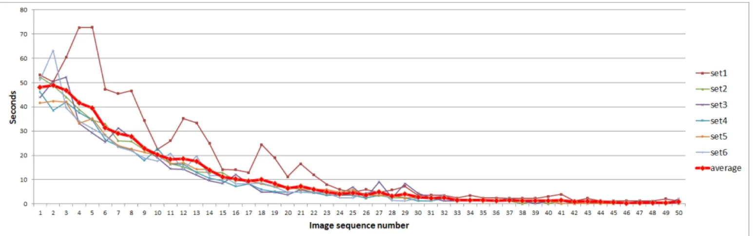
As shown in Table I, a CITRIC mote does not have a communication module on itself, but uses a TelosB for com-munication which provides 250 kbps of transmission speed. This transmission speed is the maximum possible rate and the actual speed may vary due to the changes in the wireless channel. We conducted a simple experiment to figure out how
long it would take to transmit various sizes of images. At first, we took a picture of size 320×240 on a CITRIC mote and recursively resized them by 95 % from320×240to26×19
for 50 times, and sent them back to the server and calculated the time taken to receive each size of an image. The results are shown in Figure 5. The results can be easily expected, that is, the smaller images take a shorter time to be transmitted. Unfortunately, a full size image takes 40 seconds which is too long to be used in a real-time system. In order to provide the user with a real-time service, we implemented our Virtual Lock system not to transmit the full size images but small parts of them which are the regions selected by the user because the images with the sizes smaller than72×54 takes less than 3 seconds to be transmitted.
B. Detection Rate
The Virtual Lock system we propose is a security system which detects abnormal disappearance of certain objects, so, the detection rate is the most important specification of our Virtual Lock system. We will compare the detection rates of four types of objects calculated from each CITRIC mote. The four types of objects are shown in Figure 6 and they are a laptop, box, book and bottle.
We calculated the detection rates by randomly rotating and moving those objects five times at three predetermined locations which represent close, medium and far distance, and averaged those results for each object. Those three regions are indicated in Figure 7 and the detection rate of each object from two CITRIC motes with different angle of view is shown in Table II.
As shown in Table II, a box shows the highest detection rates (>85 %) in both view points, and a laptop showed the
Fig. 5. Transmission time between CITRIC mote and server
TABLE II
COMPARISON OF DETECTION RATES OF FOUR OBJECTS CALCULATED FROM TWOCITRICMOTES
CITRIC motes CITRIC mote #1 CITRIC mote #2
Regions Region #1 Region #2 Region #3 Avg. Region #1 Region #2 Region #3 Avg. Tot. Avg. Laptop 65.2 % 67.3 % 66.1 % 66.2 % 70.4 % 73.4 % 77.9 % 73.9 % 70.1 %
Box 93.3 % 93.5 % 94.8 % 93.9 % 86.8 % 94.6 % 90.5 % 90.6 % 92.2 % Book 82.4 % 43.0 % 81.8 % 69.1 % 82.2 % 84.4 % 85.6 % 84.0 % 76.6 % Bottle 79.0 % 87.5 % 84.6 % 83.7 % 83.0 % 76.8 % 79.0 % 79.6 % 81.7 %
(a) Laptop (b) Box (c) Book (d) Bottle
Fig. 6. Four kinds of objects
lowest detection rates. That’s because of the shapes of the objects. The box looks almost always like a rectangle or a cube which fits the user’s rectangular selection area very well, but the laptop does not, because the laptop looks like just an ‘L’ shaped object when it is seen from its sides, so, it can not fit the selection area enough and results in low detection rate. However, The laptop still guarantees at least 60 % of detection rates. The book and bottle showed relatively low detection rates, and it is also because of their shapes. They always can not fit the user’s selection area, because the book almost always looks like a diamond, as shown in Figure 6(c), and the bottle also can not fit the selection area due to its curved shape as shown in Figure 6(d). Those four kinds of objects showed the detection rates higher than 60 %. If the selection area is freely adjustable by the user to select the objects exactly, we expect higher detection rates.
V. DEMORESULTS
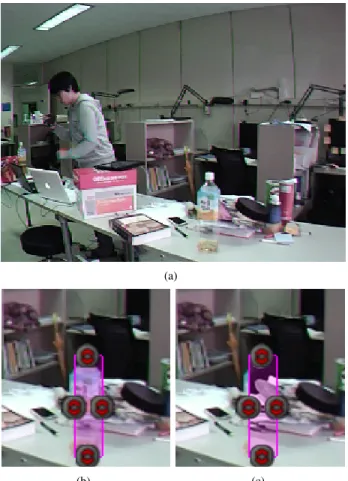
We demonstrated our Virtual Lock system in a real situation. As shown in Figure 8(a), there was a precious bottle on the desk, and we set the Virtual Lock system using iPad which is
(a) CITRIC mote #1 (b) CITRIC mote #2
Fig. 7. Three regions. BLUE for region #1, GREEN for region #2, and RED for region #1, respectively.
compatible with an iPhone to watch the bottle (Figure 8(b), with 62 % of sensitivity, 9 seconds of period, and 2 times for repeated event detection. Suddenly, someone took the bottle, the camera sensor network detected that the bottle was gone and notified the user, the iPhone application showed the user the image that the bottle is gone as shown in Figure 8(c). More experiments were conducted with various objects and the Virtual Lock system reported missing objects reliably for each case.
VI. CONCLUSION
We proposed a portable security system using wireless camera sensor networks, lightweight computer vision algo-rithms, and the experimental results and demo results showed the promise of the Virtual Lock system. In this paper, we implemented the event detection algorithm using the image difference method which is simple but not robust enough under different environments. we plan to use more reliable
(a)
(b) (c)
Fig. 8. (a) shows the image of real situation take by the CITRIC mote. (b) shows the region selected by the user. (c) shows the notification of missing bottle.
algorithms using HOG or SIFT features for event detection. Furthermore, we plan to improve the scalability of the system such that it can support multiple iPhones and a large number of camera motes. The the Virtual Lock system can be easily deployed at any place since it is based on an ad-hoc wireless network of camera sensor motes. This is the major difference to the traditional CCTV systems which require additional equipments such as power cables, data cables and employees to take care of the system. However, we envision that the Virtual Lock system operates with existing CCTV camera networks and provides safety and security for wider areas.
ACKNOWLEDGEMENT
This research was supported by Basic Science Research Program through the National Research Foundation of Korea (NRF) funded by the Ministry of Education, Science and Technology (No. 2010-0027155).
REFERENCES
[1] T. Yan, D. Ganesan, and R. Manmatha, “Distributed image search in camera sensor networks,” inProc. of the 6th ACM/IEEE International
Conference on Embedded Networked Sensor Systems (SenSys), 2008.
[2] A. Basharat, N. Catbas, and M. Shah, “A framework for intelligent sensor network with video camera for structural health monitoring of bridges,” inProc. of the 3rd IEEE International Conference on
Perva-sive Computing and Communications Workshops (PerCom) Workshops,
2005.
[3] J. Shin, R. Kumar, D. Mohapatra, U. Ramachandran, and M. Ammar, “Asap: A camera sensor network for situation awareness,” inProc. of the 11th International Conference on Principles of Distributed systems
(OPODIS), 2007.
[4] T. Teixeira, D. Lymberopoulos, E. Culurciello, Y. Aloimonos, and A. Savvides, “A lightweight camera sensor network operating on sym-bolic information,” inProc. of the ACM/IEEE International conference on Embedded Networked Sensor Systems (SenSys) Workshop on
Dis-tributed Smart Cameras, 2006.
[5] T. Teixeira and A. Savvides, “Lightweight people counting and local-izing in indoor spaces using camera sensor nodes,” in Proc. of the 1st ACM/IEEE International Conference on Distributed Smart Cameras
(ICDSC), 2007.
[6] K. Heath and L. Guibas, “Multi-person tracking from sparse 3d tra-jectories in a camera sensor network,” inProc. of the 2nd ACM/IEEE
International Conference on Distributed Smart Cameras (ICDSC), pp.
1–9.
[7] K. Morioka, J. Lee, and H. Hashimoto, “Human-following mobile robot in a distributed intelligent sensor network,” IEEE Transactions
on Industrial Electronics, vol. 51, no. 1, pp. 229–237, 2004.
[8] I. Rekleitis, D. Meger, and G. Dudek, “Simultaneous planning, lo-calization, and mapping in a camera sensor network,” Robotics and
Autonomous Systems, vol. 54, no. 11, pp. 921–932, 2006.
[9] T. Ellis, “Multi-camera video surveillance,” inProc. of the 36th IEEE
International Carnahan Conference on Security Technology (ICCST),
2002.
[10] A. Prati, R. Vezzani, L. Benini, E. Farella, and P. Zappi, “An integrated multi-modal sensor network for video surveillance,” inProc. of the 3rd
ACM International Workshop on Video surveillance & sensor networks,
2005.
[11] C. Park and P. Chou, “eCAM: ultra compact, high data-rate wireless sensor node with a miniature camera,” inProc. of the 4th ACM/IEEE International conference on Embedded Networked Sensor Systems (Sen-Sys), 2006.
[12] M. Rahimi, R. Baer, O. Iroezi, J. Garcia, J. Warrior, D. Estrin, and M. Srivastava, “Cyclops: in situ image sensing and interpretation in wireless sensor networks,” inProc. of the 3rd ACM/IEEE International
conference on Embedded Networked Sensor Systems (SenSys), 2005.
[13] I. Downes, L. Rad, and H. Aghajan, “Development of a mote for wireless image sensor networks,”IEEE Transactions on COGnitive systems with
Interactive Sensors (COGIS), Paris, France, 2006.
[14] “xbow.” [Online]. Available: http://www.xbow.com/
[15] P. Chen, P. Ahammad, C. Boyer, S. Huang, L. Lin, E. Lobaton, M. Meingast, S. Oh, S. Wang, P. Yanet al., “CITRIC: A low-bandwidth wireless camera network platform,” in Proc. of the 2nd ACM/IEEE
International Conference on Distributed Smart Cameras (ICDSC), 2008.
[16] H. Bay, T. Tuytelaars, and L. Van Gool, “Surf: Speeded up robust features,” in Proc. of the European Conference on Computer Vision
(ECCV), 2006.
[17] N. Dalal and B. Triggs, “Histograms of oriented gradients for human detection,” in Proc. of the IEEE Computer Society Conference on
Computer Vision and Pattern Recognition (CVPR), 2005.