A Pattern Language for Evolution in Component-Based Software Architectures
Aakash Ahmad, Pooyan Jamshidi, Claus Pahl, Fawad Khaliq†
Lero – the Irish Software Engineering Research Centre School of Computing, Dublin City University, Ireland.
†Department of Computer Science, Quaid-i-Azam University, Islamabad, Pakistan
[ahmad.aakash || pooyan.jamshidi || claus.pahl]@computing.dcu.ie, †[email protected]
Abstract–– Modern software systems are prone to a continuous evolution under frequently varying requirements. Architecture-centric software evolution enables change in system structure and behavior while maintaining a global view of software to address evolution-centric tradeoffs. The Lehman’s law of continuing change demands for long-living and continuously evolving architectures to prolong the productive life and economic value of deployed software. However, the existing solutions for architectural maintenance and evolution fall short of exploiting generic and reusable expertise to address recurring evolution problems. We argue that architectural evolution process requires an explicit evolution-centric knowledge – that can be discovered,
shared and reused – to anticipate and guide change management. Therefore, we propose a pattern language (PatEvol) as a collection of interconnected change patterns that enable reuse-driven and consistent evolution in component-based software architectures (CBSAs). Pattern interconnections represent possible relationships among patterns (such as variants or related patterns) in the language. In component-based architectures, hierarchal configurations of atomic and composite elements express computational components and their connectors to develop and evolve software. More specifically, component-based architecture models and their evolution define the target domain of proposed pattern language. In general, we integrate architecture change mining (PatEvol development) as a complementary and integrated phase to facilitate reuse-driven architecture change execution
(PatEvol application). Reuse-knowledge in the proposed pattern language is expressed as a formalised collection of interconnected-patterns. Individual patterns in the language build on each other to facilitate a generic, first-class abstraction – that can be operationalised and parameterisaed – to address recurring evolution tasks. The pattern language itself continuously evolves with an incremental acquisition of new patterns from architecture change logs.
Keywords –– Pattern Definition, Pattern Detection, Pattern Language, Software Architecture Evolution, Evolution Reuse
I.INTRODUCTION
Modern software systems operate in a dynamic environment with frequent changes in stakeholders’ needs, business and technical requirements and operating environments [1, 2]. These changing requirements trigger a continuous evolution in deployed software that must be addressed while maintaining a global system view to effectively resolve evolution-centric tradeoffs [2]. Component-based software architecture (CBSA) [29, 3] models a system’s structure as hierarchical configurations of computational components and their interconnections by abstracting implementation-specific details. The role of CBSA – as a blue-print of evolving software – is pivotal to fill the gap between changing requirements [6] and refactored source code.
Lehman’s law of continuing change [2]poses a direct challenge for research and practices that aim to support long-living and
continuously evolving architectures [4, 5] under frequently varying requirements [6]. The law states that “…systems must be continually adapted or they become progressively less satisfactory”. Therefore, the implications of a continuous change [2] have resulted in development of solutions that enable reusable, off-the-shelf expertise to address recurring evolution problems [4, 5]. The existing solutions promoted the ‘build-once, use-often’ philosophy by exploiting change patterns [6, 7] and
evolution styles [4, 5, 8] to address a continuous evolution in software architectures. However, systematic analysis of existing research [9, 10] highlights the needs for integration of evolution-centric knowledge acquisition [14] that guides knowledge application [30] to evolve software architectures.
Recently, we conducted a systematic literature reviews to classify and compare existing research and practices that a) enable architecture evolution [9] and b) facilitate architecture evolution reuse [10]. We observed that a critical challenge to tackle recurring evolution lies with a continuous (empirical) acquisition of evolution-centric knowledge and its application during evolution. In [10], we define evolution reuse-knowledge as:
“[…] a collection and integrated representation (problem-solution map) of analytically discovered, generic and repeatable change implementation expertise that can be shared and reused as a solution to frequent (architecture) evolution problems”. Although reuse in existing solution is (pre-dominantly) achieved through change patterns and evolution styles to enable evolution, existing solutions for architectural maintenance and evolution fall short of exploiting knowledge-driven reuse. We believe that the potential beyond individual patterns and styles could only be maximised with a network of patterns that build on each other to enable an incremental and reuse-driven evolution in architectures [11, 12]. Therefore, we propose a language (PatEvol) as a formalism and collection of change patterns that support reusable solutions to recurring evolution problems. Pattern interconnections (a.k.a patterns network) allow possible relationships to exist among
patterns (such as variants or related patterns) in the language.
By exploiting the vocabulary and grammar of a language, individual patterns can be formalised and interconnected to support reusable, off-the-shelf evolution expertise. Our solution is fundamentally inspired by Alexander’s seminal theory [13] about pattern languages that integrate patterns as repeatable solution to build complex architectures. We identify the central research challenge as: How to foster an explicit evolution-centric knowledge that enables modeling and executing reuse of frequent evolution tasks in component-based software architectures? We now highlight challenges in pattern-based evolution and pattern languages to discuss proposed contributions.
A. Pattern-based Reuse in Architecture Evolution – Reuse-knowledge in the proposed pattern language is expressed as a formalised collection of interconnected patterns. Patterns with their possible variants must be discovered by analysing the
problem space and the solution context. Therefore, we propose to integrate architecture change mining as a complementary phase for a continuous incremental acquisition of evolution-centric knowledge to enable reuse in change execution. Change mining
enables postmortem analysis of architecture evolution histories [14, 15] to i) discover change patterns and ii) derive a pattern language (PatEvol) as a collection of evolution reuse-knowledge.
Change execution relies on the network of composed patterns in PatEvol to formalise problem solution view to enable reusable evolution.
B. Pattern Selection Problem –The pattern selection problem is a significant challenge for in-experienced developers or architects to search and select the appropriate patterns from large collections [27]. With a language-based formalism we exploit the Question-Option-Criteria (QOC) methodology [16] to address the pattern selection problem. The QOC methodology is adopted from design space analysis [28] to select the most appropriate pattern from the language collection by evaluating the forces and consequences of given patterns [7].
C. Target Domain of Pattern Language – Component-based architecture models [29] and their evolution define the target domain of the pattern language. More specifically, proposed patterns in the language enable addition, removal or modification of components and their interconnections in the architecture [3, 4]. In this paper, we adopt the C2 architecture style [22] for the description of CBSAs. Pattern-based evolution is restricted to evolve architectural components and their connectors. In such component-based models, we must preserve the structural integrity of atomic and composite components to ensure architectural consistency before and after evolution. We present evolution case of an electronic payment system to illustrate the proposed solution.
In addition, we provide a prototype to support automation along with an appropriate user-intervention to guide pattern-based evolution. The contribution of the proposed solution lies with: – In the context of patterns [6, 7] and style-based [4, 5] evolution, the solution promotes a continuous discovery of architecture change patterns by investigating evolution histories [14, 15]. – We also go beyond individual patterns [7] to specify formal vocabulary, grammar and pattern sequencing to develop a language for interconnected systems of patterns to evolve CBSAs. – In general [9, 10], we also unify the processes of i) architecture change mining to discover and share evolution-centric reuse-knowledge that guides ii) architecture change execution.
Background on pattern discovery and pattern modeling is detailed in Section II with challenges and proposed solution in Section III. Structural composition in the pattern language is presented in Section IV with target domain of the pattern language described in Section V. We illustrate pattern-driven evolution in Section VI and detail the implementation in Section VII. Related work is detailed in Section VIII, conclusions and outlook in Section IX.
II.BACKGROUND
In this section, we primarily focus on elaborating aspects of
pattern discovery and pattern modeling as the background context to deriving the pattern language.
A. Patterns Discovery from Architecture Change Logs
Considering the role of reuse in evolution [10], change patterns emerged as an established solution – enabling reuse-knowledge – to address the co-evolution of architecture
models [6], architecture-based integration [7] and self-adaptations [17]. However, based on a taxonomical evidence of pattern-based evolution [6, 7] we observed a lack of experimental methodologies for pattern discovery. In contrast to existing solutions [7], we argue for change patterns as discovered knowledge – from established knowledge sources – that can be shared and reused to guide evolution. Therefore, we build on our previous research [14, 15] that primarily focused on graph-based discovery of patterns from architecture change logs. We exploited change logs as a transparent and centrally manageable repository of architecture change instances for the post-mortem analysis of architecture evolution and to discover change patterns. Additional details about our algorithmic solution, formalism and tool support for change pattern discovery are presented in [14]. Critical aspects of pattern discovery include:
– Source of Pattern Discovery is represented as change logs [15] that maintain traces of architecture change history in a sequential way. Log-based investigation of architecture evolution is significant in providing an updated central repository with analytical support to search, query and analyse change representation and to ultimately discover change patterns.
– Formal Methodology for Pattern Discovery is employed by means of graph-based models to represent change instances from logs as an attributed graph [18]. Graph-based modeling of architecture change facilitates sub-graph mining approaches [14] to a) analyse change operationalisation, b) identify operational dependencies and c) discover change patterns.
– Algorithmic and Tool Support for Pattern Discovery [15] introduces the pattern discovery problem as a modular solution. It enables automation along with appropriate user intervention and customisation through parameterisation for the pattern discovery process [14]. We provide a prototype (G-Pride: Graph-based Pattern Identification) for process automation and scalability.
B. Meta-model of Architecture Change Patterns
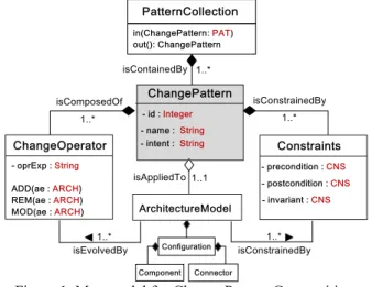
In change logs, we observed that the operationalisation of individual changes represent a parameterised procedural abstraction. This helps us to define change pattern as: “[…] a generic, first class abstraction to support potentially reusable architectural change execution”. We formally express pattern-based change as: PatEvol = < ARCH, OPR, CNS, PAT, COL>. Structural composition and relationships among pattern elements are illustrated as pattern meta-model in Figure 1.
1. Architecture Model (ARCH) refers to the architecture elements to which a pattern can be applied during change execution. We represent a CBSA model as topological
configurations (CFG) based on a set of architectural components
(CMP) as the computational entities that are linked through
connectors (CON) [3]. Please note that we follow the C2 architecture style [22] for architecture descriptions with an implicit representation of configurations through interconnected
components. Therefore, consistency of pattern-based change and structural integrity of architecture elements beyond this architecture model is undefined. Additional details about component-connector architecture model along with its evolution scenarios are provided in Section IV.
Figure 1. Metamodel for Change Pattern Composition.
2. Change Operators (OPR) represents change instances that are fundamental to operationalising architectural evolution. Our analysis of the change log [14, 15] goes beyond basic change types in [19] to specify a set of atomic and composite operations enabling structural evolution by adding (ADD), removing (REM) and modifying (MOD) elements in CBSAs. Architectural composition during change operationalisation is preserved with: – Atomic Change Operations: theseenable fundamental changes in terms of adding, removing or modifying the component operation (OPT), component port (POR), connector binding (BIN), connector endpoint (EPT).
– Composite Change Operations: are a collection of atomic change operations, combined to enable composite architectural changes. These enable adding, removing or modifying the components (CMP), connectors (CON) and configurations (CFG) with a sequential composition of architectural changes.
3. Constraints (CNS) refer to a set of pattern-specific constraints in terms of pre-conditions (PRE) and post-conditions (POST) to ensure consistency of pattern-based changes. In addition, the
invariants (INV) ensure structural integrity of individual architecture elements during change execution.
4. Change Patterns (PAT) defines a first-class abstraction that can be operationalised and parameterised to support potentially reusable architectural change execution as:
PAT<name, intent>: PRE(aem∈ARCH)
∈
→ POST(ae′m∈ARCH). A pattern has a name and an intent that represents a recurring, constrained (CNS) composition of change operationalisation (OPR) on architecture elements (aem∈ ARCH).
5. Collection (COL) is arepository infrastructure that facilitates an automated storage (in: once-off specification) and retrieval
(out: multiple instantiation) of discovered change patterns. In addition to elements of the meta-model, pattern variants represents variations among possible instantiaions of a pattern. Pattern instances and their possible variants are discussed in
Section IV. The background details about pattern discovery and representation help us to outline the research challenges and proposed solution (Section III) with structural composition of patterns (Section IV).
III.RESEARCH CHALLENGES AND PROPOSED SOLUTION In Section II (cf. Figure 1), an individual change pattern outlines the core of (repeatable) solutions to resolve recurrent evolution problems. The potential of change patterns could only be achieved, if individual patterns are applied in the context of each other – establishing a network of related pattern – known as a
system or language of patterns [11, 13]. For this reason, we claim that a language-based formalised collection facilitates an iterative pattern selection and their application to enable an incremental evolution in architectures. By incremental evolution we mean decomposing evolution process into a manageable set of evolution scenarios that could be addressed in a step-wise manner [11]. However, we also identified research challenges based on our experience with pattern mining [14, 15], literature survey [9, 10] and following related research [4, 5]. We identify three critical challenges elaborated in Section III A to discuss the proposed solution in Section III B.
A. Research Challenges
We outline the core research challenges as: i) discovering change patterns (and their variants), ii)establishing pattern relationships in a language context and iii)selecting appropriate patterns in a given evolution scenario.
Challenge I – Discovery of Change Pattern refers to the application of change mining process for investigating evolution-centric knowledge sources (change logs) in order to analyse and identify frequent data sets (change sequences as patterns)[14].
In contrast to synthesised pattern definition in [6, 7], we investigated architecture change logs [15] to discover a classified composition of change patterns and their possible variants (see Section II A). Technical challenges include the complexity of pattern discovery, selection and application of formal methodologies, development of algorithmic solutions and tool support already detailed in our previous research [14, 15].
Challenge II – Development of Pattern Relationships refers to the possible interconnection(s) among patterns in a collection
(language) that build on each other to support an incremental solution (step-wise pattern application) for evolution problems.
The challenge lies with establishing the relationships or an order of application for individual patterns in the collection [11]. Pattern interconnection requires creation of either static, dynamic
or both types of relations among change patterns. Static or predefined relations express specialised and generalisedtype of patterns in the language. Static pattern relations are limiting when expressing sequential relations among the patterns in the language. In contrast, sequential or dynamic relations determine if a pattern is dependent on or independent of other patterns in the language. In an ideal context, a pattern language must support dynamism in creation or destruction of pattern relations driven by the context of evolution.
Challenge III – Selection of Patterns from a Collectionrefers to a flexible mechanism for querying, searching and selecting the most appropriate change pattern from language collection.
Pattern selection is a significant challenge for inexperienced developers or architects due to searching of required patterns in growing collections and selecting the appropriate patterns or possible alternatives [27]. In situations of pattern selection, systematically applying patterns requires a certain amount of expertise from the software architect or designer. More specifically, the architect/designer has to understand how a pattern solution fits into the overall architecture evolution problem and how other patterns can be applied to resolve consequences of applying the first pattern. Change patterns require expertise from the architects in terms of mapping the problem-solution for the domain in which the patterns should be applied. Some of the typical questions arising for an architect could be: Which pattern should I choose first? Which variant of the pattern works best? Which pattern should be applied next?
B. Overview of the Proposed Solution
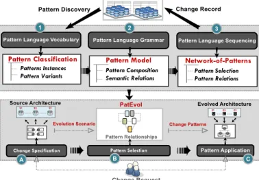
In order to support a formalised system of patterns for reusable evolution and addressing the challenges in Section III A, we illustrate our solution in Figure 2. We propose architecture
change mining as a complementary and integrated phase to
architecture change execution. This means, reuse knowledge and expertise discovered during change mining can be shared and reused (as patterns) to guide architecture change execution.
Figure 2. Overview of Proposed Solution – Change Mining (PatEvol
Development) and Change Execution (PatEvol Application).
1. Architecture Change Mining – we propose architecture
change mining (PatEvol development) to empirically derive an explicit reusable knowledge [10] as a pattern language for architecture evolution. The language presents a formalised collection of change patterns to map problem-solution view of the domain (i.e; evolving CBSAs).
– Addressing the Pattern Discovery Problem: we investigate architecture change logs [14] to discover a classified composition of change patterns and possible variants (i.e.,
vocabulary) in Figure 2.
– Model for Pattern Representation: to express the structural composition of patterns (cf. Figure 1) that also governs the semantic relationships among pattern elements (i.e., grammar). – Establishing the Pattern Relationships: In our solution an important task includes creating a network-of-patterns that
provides a foundation to establishing the relations among change patterns (i.e., pattern sequencing). Therefore, the reuse-knowledge is expressed as a collection of interconnected patterns to facilitate a generic and reusable evolution in CBSAs.
2. Architecture Change Execution –refers toexploiting patterns and their relations in a pattern language to address the evolution scenarios by mapping the problem-solution view of the domain (i.e., family of evolving CBSAs). In Figure 2, we propose architecture change execution (PatEvol application) as pattern-driven reusable evolution of component-architectures. In the proposed solution, an architect specifies change request (as addition, removal, or modification) of elements in existing CBSA. A declarative specification of change requests enables the selection of appropriate pattern sequences to derive a reusable evolution strategy based on given evolution scenarios. Pattern language provides a method of systematic reuse based on an incremental application of patterns from collection.
– Addressing the Pattern Selection Problem – During change execution, pattern selection problemis addressed by adopting and customising the Question-Option-Criteria (QOC) methodology [16]. The QOC methodology helps us to select the most appropriate pattern from the language collection by evaluating the forces and consequences of a given patterns during evolution [6, 7, 11]. QOC allows analysis for an i) explicit representation of alternative evolution strategies and the ii) rationale for choosing among available strategies (a.k.a. pattern selection).
IV.STRUCTURAL COMPOSITION OF PATTERN LANGUAGE The pattern language is formally composed of i) a classified composition of patterns and their variants (1.
Vocabulary: ) along with a ii) set of rules that govern the structure and semantic relations among pattern elements (2.
Grammar: ) to create a iii) network of patterns (3. Sequencing: ). We formalise the structural composition of pattern language as: ( x x ) =
[ { } { } ]
In Section IV A, we provide technical details to justify graph-based formalisation of pattern language grammar.
A. Graph-based Formalisation of the Language Grammar
The language grammar ( ) is represented as the structural
composition of pattern model and semantic relationships among elements in a pattern meta-model (cf. Figure 2). One of the most critical concerns among pattern language composition is the formalisation of the pattern language grammar [24, 25].
In contrast to aspect weaving [24] to derive pattern sequences, we prefer attributed graphs to formalise language grammar because:
Listing 1. Graph-based Template for Change Pattern Specification (GraphML notation) [20]. – Establishing Static and Dynamic Relationships: In contrast to
rigid interconnection among patterns [24, 25], attributed graph-based modeling [18, 20] allows capturing the semantics of pattern relationships. More specifically, attributed graph is represented as pattern language with individual pattern as attributed nodes and pattern relationships as attributed edges of a graph (Listing 1). – Pattern Matching and Selection: If individual patterns are represented as graph nodes, we can exploit sub-graph isomorphisms [26, 31] (based on node matching) to select individual patterns (i.e., nodes) from language (i.e., graph). – Visualising Pattern Composition and Relations: Enables
Abstracting a complex pattern hierarchy. Pattern visualisation greatly facilitates with analysing pattern structure to evaluate possible consequences and alternatives in given evolution context.
– Graph Network of Patterns: to define possible relationships among patterns in the language. Graph-based structure allows a flexible mechanism to search and retrieve patterns efficiently. We formalise a pattern vocabulary as an attributed graph (AG) with nodes and edges typed over an attributed typed graph (ATG) [18]. The mappings for the graph-based notation and vocabulary as a template-based structure are summarised in Listing 1 using the Graph Modeling Language (.GML format). The pattern language grammar as a nested attributed graph is expressed as 6-tuple:
= <GTMP, NCLS, GPAT, NCMP, ESEQ, NREL>
A change pattern template provides a structured documentation to capture details of individual patterns [19].
Graph-based Template for Pattern Specification A template-based specification allows us to explicitly represent the context of evolution (i.e., evolution scenario(s)) along with the forces and possible consequences of appropriate pattern to address the scenario. Therefore, we provide a template for pattern specification that is based on the pattern meta-model and the guidelines for documenting architectural styles presented in [19]. We map each of the elements of the pattern meta-model (from Figure 1) to the possible relationships among the pattern elements in the template provided in Listing 1. However, change pattern meta-model only illustrates a structural composition of patterns elements. In order to enable compositional semantics for pattern elements, we also address binary compositional relationships among a change pattern (P) and its constituent element (E) given as a tuple P ← E : <Classifies,
ComposedOf, ConstrainedBy, Evolves, hasVariant, follows>. For example, the possible relation among an instance of pattern and operators is specified as: Pattern ← Operators.
1. [Classifies: PAT ← CLS] – defines the classification of change pattern instances in the pattern language grammar. Pattern classification therefore defines a logical grouping of change patterns based on their impact of change on architecture model.
2. [ComposedOf: PAT ← OPR] – defines the change operational composition in a given pattern instance. It reflects the type of change operations (Add<>, Rem<>, Mod<>) and the operational composition (atomic, composite operators) that specify the change operationalisation.
3. [ConstrainedBy: PAT ← CNS)] – defines a set of constraints that ensure the structural integrity of architecture models before and after change pattern application. Constraints specify the preconditions (architecture model before pattern
1.Pattern Template [GTMP] - outer graph (Line 02 - 36) 2. Pattern Classification [NCLS] - outer graph node (Line 04 - 33) 3. Pattern Specification [GPAT] - inner graph (Line 07 - 32) 4.Pattern Composition [NCMP] - inner graph nodes (Line 09 –29)
5.Pattern Composition Relationships [ESEQ] - inner graph edges (Line 15 – 31) 6. Pattern Sequencing in the Language [NREL] - outer graph edge (Line 34 - 35)
application), the invariants (preserving the compositional hierarchy of architecture model during change) and post-conditions (architecture model after pattern application).
4. [Evolves: PAT ← ARCH] – defines the application of a change pattern on a given architecture model. Additional details about the composition hierarchy in architecture models are presented in Section V.
5. [hasVariant: (PAT ← VAR)] – defines the relationship between a pattern and its variants. The variant of a pattern has the same structure and semantics as a pattern, however it represents the variations among the possible implementations of a pattern.
6. [Follows: PATJ
← PATK)] – defines the sequence among
two change patterns PATJ follows PATK. In order to develop
pattern system, patterns have to be applied in a specific order defined by one or more pattern sequences. The sequence < PATJ,
PATK, PATL > means a pattern PATJ is selected before pattern
PATK, which itself is selected before PATL.
B. Language Vocabulary – Change Pattern and their Variants
The language vocabulary ( ) is a classified (CLS)
composition of change pattern (PAT) instances and their possible variants (VAR) expressed as (1), where represents a composition operator. Technical details about discovering pattern instances and their variants (language vocabulary) are detailed in [14, 15] (Section III A). In this section, we focus on specifying discovered pattern instances in a pattern template developed by following the grammar (Listing 1). Based on guidelines to document architecture styles [19], we specify patterns by capturing a) Pattern Description, b) Context and Forces and c)
Pattern Variants.
Pattern Description
Component Mediation ([CM] <C1, CM, C2>)
Intent – To integrate a mediator component (CM) among two or more
directly connected components (C1, C2)
Context and Forces Constraints – before, during and after change. – Preconditions C1 and C2 must be directly connected.
– Invariants C1 and C2 must be disconnected.
– Post-conditions C1 and C2 must connected with CM.
Change Operators – to apply architecture restructuring. – Add a Component CM
– Remove a Connector X1
– Add a Connector Y1
– Add a ConnectorY2
Architecture Models – the affected architecture model.
Pattern Variant(s) Component Mediation has two variants
– Variant 1: Parallel Mediation refers to addition/removal of the architectural elements that provide alternative/parallel functionality. – Variant 2: Co-related Mediation refers to adding/removing a set of functionally co-related architecture elements into the existing model.
Pattern 1 - Component Mediation Pattern
Functional Slicing([C] <C1, C2>)
Intent – To split a component (C) into two or more components (C1,
C2) for functional decomposition of C. Constraints – before, during and after change. – Preconditions C already exists in the architecture. – Invariants N/A.
– Post-conditions C removed, C1 and C2 must be added. Change Operators – to apply architecture restructuring. – Move out a Component C1 from C
– Move out a Component C2 from C
– Remove a Component C
Pattern 2 – Functional Slicing Pattern
Functional Unification(<C1, C2> [C])
Intent – To merge two or more components (C1, C2) into a single
component (C) for functional unification of (C1, C2).
Constraints – conditions before, during and after change. – Preconditions C1 and C2 already exist in the architecture.
– Invariants N/A
– Post-conditions C1 and C2 removed, C is added.
Change Operators – to apply architecture restructuring. – Add a Component C
– Move in a Component C1 from C
– Move in a Component C2 from C
Pattern 3 – Functional Unification Pattern.
Active Displacement(<C1:C2>, <C1:C3> [C2:C3])
Intent – To replace an existing component (C2) with a new
component (C3) while maintaining the interconnection with existing
component (C1, C2).
Constraints – conditions before, during and after change. – Preconditions C1 and C2 must be directly connected.
– Invariants C1 exists in architecture, C2 is removed.
– Post-conditions C1 connected to a new component C3. Change Operators – to apply architecture restructuring. – Remove a Component C2
– Remove a Connector X1(C1, C2)
– Add a Component C1
– Add a Connector X2(C1, C3)
Pattern 4 – Active Displacement Pattern.
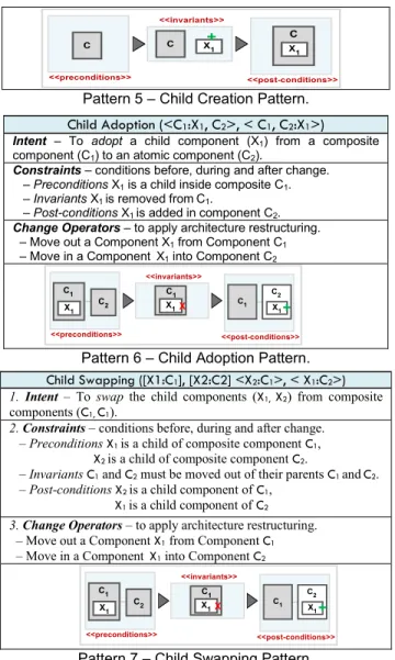
Child Creation ([C1] <X1:C1>)
Intent – To create a child component (X1) inside an atomic
component (C1).
Constraints – conditions before, during and after change. – Preconditions component C1 is an atomic component.
– Invariants C1 and C2 must be disconnected.
– Post-conditions X1 is a child component of C1. Change Operators – to apply architecture restructuring. – Add a Component X1
Pattern 5 – Child Creation Pattern.
Child Adoption (<C1:X1, C2>, < C1, C2:X1>)
Intent – To adopt a child component (X1) from a composite
component (C1) to an atomic component (C2).
Constraints – conditions before, during and after change. – Preconditions X1 is a child inside composite C1.
– Invariants X1 is removed fromC1.
– Post-conditions X1 is added in component C2. Change Operators – to apply architecture restructuring. – Move out a Component X1 from Component C1
– Move in a Component X1 into Component C2
Pattern 6 – Child Adoption Pattern.
Child Swapping ([X1:C1], [X2:C2] <X2:C1>, < X1:C2>)
1. Intent – To swap the child components (X1, X2) from composite components (C1, C1).
2. Constraints – conditions before, during and after change. – PreconditionsX1 isa child of composite component C1, X2 isa child of composite component C2.
– InvariantsC1 and C2 must be moved out of their parents C1 and C2. – Post-conditionsX2 is a child component of C1,
X1 is a child component of C2 3. Change Operators – to apply architecture restructuring. – Move out a Component X1 from Component C1
– Move in a Component X1 into Component C2
Pattern 7 – Child Swapping Pattern.
C. Language Sequencing – Change Pattern Relationships
Once grammar (Section IV A) and vocabulary (Section IV B) are specified, we could derive pattern sequences conforming to the language, as presented in Figure 3. More specifically, a pattern language provides a topology to derive sequences, similar to the natural language where the grammar provides the structure for generating sentences. An important question is ‘why we choose a particular sequence of patterns among the possible alternatives in the language’. In the literature, pattern sequencing is derived based on a pattern hierarchy [24] (e.g., large patterns must be on top of smaller patterns) or using the annotated grammar [25] with the Question Option Criteria methodology [16]. In contrast, we distinguish static sequences as well as dynamic sequences. – Static Sequence of Patterns allows a pre-determined, mostly manual analysis of the domain to create a fixed sequence among the patterns. An example of the static sequencing is provided in Figure 3. In Figure 3 we derive a sequence that is interpreted as ComponentMediation <follows> ActiveDisplacement: “if the replacement of a component is required”. A pattern sequence annotation in the language (Listing 1 Line 34-35) is:
Limitations – static sequencing is a rigid structure of the pattern language with minimal flexibility. This could be particularly limiting in a context where the exact sequences of patterns depend on some arbitrary evolution scenario. For example, in many situations we might need the application of ActiveDisplacement pattern directly preceding ComponentMediation. This clearly violates the static sequence, in-fact a static-sequence only represents a specific organisation or patterns that must be dynamically adjusted.
– Dynamic Sequence of Patterns – in contrast to static ones, they provide a flexible sequence by means of dynamic relationships among patterns. In order to support dynamic sequences, we follow the design-space analysis for patterns [25] based on the Question Option Criteria (QOC) [16].
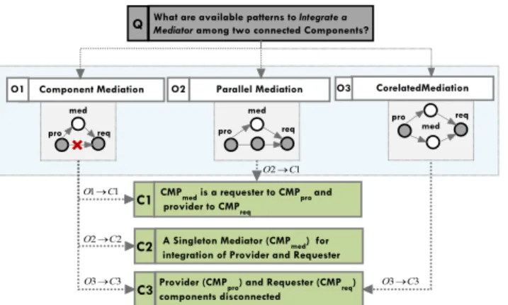
1. Question – What is the available pattern to integrate a mediator component in architecture?
2. Option – ComponentMediation is available with variants Parallel Mediation and Corelated Mediaton
3. Criteria – The consequence of ComponentMediaton is the integration of a mediator component among two or more directly connected components.
We generalise the dynamic sequencing of patterns in the language as follows where represents a sequencing operation: { }
Figure 3. An Overview of Change Pattern Language. V.TARGET DOMAIN OF PATTERN LANGUAGE The pattern language embodies its knowledge by empirically investigating change representation in evolving CBSA models [14, 15, 11]. Therefore, the applicability (target domain) of the proposed pattern language is limited to CBSA models and their evolution. In this section, we focus on presenting an overview of CBSA for an EBPP (Electronic Billing Presentment and Payment) case study1 and elaborate on EBPP evolution scenarios. A. Description of Composition-Based Architecture Models
Architectural descriptions of a composition-based architecture model as an attributed graph are presented in Figure 4. One of the most prominent representations for CBSA could be provided with
1
NACHA – EBPP A Case Study on Electronic Bill Presentment and Payment: http://www.nacha.org/ebpp
<edge id=”Follows” source=”ComponentMediation” target=”ActiveDisplacement”> <desc> if the replacement of a component is required </desc> </edge>
architecture description languages [21] or UML model [22]. We present the architecture meta-model as an attributed type graph (ATG) [18], while a possible architectural instance (Figure 4) is represented as an attributed graph (AG) that is typed over ATG. We prefer graph-based modeling mainly because: if architecture can be modeled as a graph, we could exploit graph transformations to evolve the architecture in a formal, automated way [26]. More specifically, exploiting the Double Push Out graph transformation [26] maintains the structural integrity of evolving architecture (further details in Section VI).
In Figure 4, the CBSA model represents Architectural Configuration (CFG: cfg_Payment) as a composition of computational Components (CMP: cmp_CustPayment, cmp_Invoice) and their Connectors (CON: con_invoicePay). Furthermore, each component must contain a Port for communication and atomic components (cmp_CustPayment) could be composed into composite ones (cmp_WeekPayment, cmp_MonthPayment). Connectors must contain Endpoints to allow component-level binding.
Figure 4. Structured Description of CBSA Model.
B. Component and Connector Architectural View for EBPP
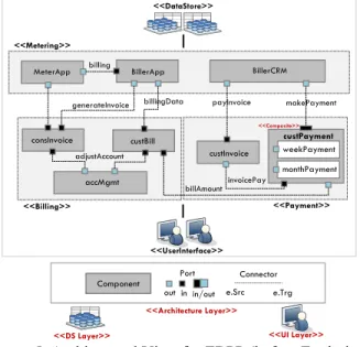
A high-level component and connector view for EBPP is presented in Figure 5, expressed in the C2 architectural style [22]. For illustrative reasons, we abstract the details about data store (DS) and user interface (UI) layers and focus on architectural layers modeling components and connectors using implicit configurations [21, 22]. These configurations represent Metering
(to provide meter information for customer’s consumption),
Billing (to handle customer billing), and Payment (to manage customer payments corresponding to the billing amount). Following the C2 architectural style for modeling EBPP, we are specifically interested in component, connectors and the interaction (messaging) that among the components.
- Components (CMP) represents the first class entities as computational elements or data stores of the EBPP architecture model, illustrated in Figure 5. Component type classification is:
1. Atomic Component - is the most fundamental type of a component that could not be decomposed. Atomic components in
Metering configuration are BillerCRM, BillerApp and MeterApp.
2. Composite Component - represents a component that contains an internal architecture as a sub-configuration of components and connectors inside composite component. The architecture elements contained in composite components refer to its children. The only example of composite component in EBPP architecture is custPayment that has weekPayment and monthPayment as its children.
- Connectors (CON) are responsible for message passing among the component ports. Unlike component classification, the EBPP architecture has only atomic connectors for component interconnection. Example of a connector-based message passing among BillerCRM (port:out - source) and custPayment (port:in -
sink) components is expressed with makePayment connector.
Figure 5. Architectural View for EBPP (before Evolution)
C. Evolution Scenarios for EBPP Architecture
We look at some evolution scenarios to demonstrate desired changes in existing architecture model for the EBPP system. We adopt the Architecture Level Modifiability Analysis (ALMA) [23] method for scenario elicitation and analysis of EBPP architecture evolution. Based on the ALMA methodology, we follow a five-step process for selection, evaluation and
interpretation of evolution scenarios in Listing 2.
Listing 2. ALMA Method for Analysis of Evolution Scenarios.
Once we have a) analysed evolution cost (Listing 2) and b)
specified the architecture (Figure 4), we now present c) selected scenarios along with d) their evaluation and e) change impact interpretation in Table 1. A set of evolution scenarios are presented in Table 1 following ALMA [23]. Key characteristics and evolution-centric aspects across family of component-driven architecture are:
- Composite Change Execution must abstract atomic changes ([Add, Remove Modify] <Component, Connectors>) into composite ones that allow […, Integration, Composition, Replacement…] of a set of architecture elements [5, 15].
3. Scenario Selection
ES1. Integration ES2. Composition ES3. Replacement ES4. Merge (Table 3)
2. Architecture Description Descriptions of all (affected) EBPP components and connectors as C2 style (Figure 5). 1. Cost Prediction Analyse all evolution scenarios. Identify change operations to execute scenario 5. Results Interpretation Change impacts on architecture analysed with change pre/post-conditions (Table 3)
4. Scenario Evaluation
Effects of scenarios (ES1, ES2, ES3, ES4) on EBPP architecture model (Table 3)
- Evolution Reuse is a key characteristic that must enable a generic, reuse-driven change for recurring evolution problems in
component-driven architecture models [4, 5].
[X = Removal] [+ = Addition] [<preconditions> → <postconditions>]
Scenario Selection Scenario Evaluation Results Interpretation
ES1 - […] to integrate a mediator component PaymentType that facilitates the selection of a payment type mechanism among the directly connected components BillerCRM and CustPayment.
EBPP architecture is modified with addition of a new components and two connectors to mediate customer billing and payments:
opr1:= ADD(PaymentType ∈ CMP) opr12:=ADD(<getBill, selectType> ∈ CON)
ES2 - […] to compose the PaymentType component with DirectDebit and CreditPayment child components that allows a customer to avail-of flexible options for billing payments.
The internal architecture of PaymentType is modified with addition of two child components DirectDebit and CreditPayment
opr1:= ADD(DirectDebit ∈ CMP) opr12:=ADD(CreditPayment ∈ CON)
ES3 - […] to replace the component accMgmt between conInvoce and custBill components with a new functional component billInvoice that handles bill invoicings for customer payments.
Existing architecture is modified by replacing the component accMgmt with billInvoice.
opr1:= REM(accMgmt ∈ CMP) opr2:= ADD(<billInvoice ∈ CMP)
ES4 - […] to merge the MeterApp and BillerApp components into a single component MeterBilling that unifies the metering and billing functionality to reduce excess messaging in two components.
Unification of two components as a coarse-grained component to reduce un-necessary message pass among the components: opr1:= REM(BillerApp ∈ CMP)
opr2:= REM(MeterApp ∈ CMP) opr3:= REM(billing ∈ CON) opr3:= ADD(MeterBilling ∈ CMP)
Table 1. Selection, Evaluation and Interpretation of Evolution Scenarios with guidelines in ALMA [2].
-Consistency of Evolving Architecture Models ensures structural integrity and composition constraints of architecture are preserved before (preconditions) and after evolution (postconditions).
VI.PATTERN LANGUAGE SUPPORT FOR CBSAEVOLUTION After presenting the pattern language (Section IV) and architecture evolution scenarios (Section V), we now focus on pattern-language support for evolution in EBPP architecture. Language support for evolution refers to patterns that provide a generic, repeatable solution to recurring evolution scenarios. The patterns from the language could be selected and applied in a sequential fashion to support an incremental evolution [12] in CBSAs.
A. Patterns as Evolution-Centric Reuse Knowledge
Change pattern provide a generic, repeatable solution to recurring evolution problems. More specifically, evolution-centric reuse-knowledge is expressed as pattern collections that enable mapping among the problem-solution view to enable reusable evolution strategies (cf. Section III, IV). An overview of the pattern-based evolution is presented in Figure 6.
Figure 6. An overview of the Pattern-based Evolution Process. In order to utilise pattern-driven reusable evolution strategies, we adopt the design space analysis [28, 16] for a systematic pattern selection from language collections. Design space analysis is a methodology to address design-related problems in human-computer-interaction (HCI) [28]. We utilise design space analysis
for an i) explicit representation of alternative evolution strategies and ii) the rationale for choosing among available strategies. Figure 6 illustrates:
– Problem Space that represents evolution scenarios that we identified from the EBPP case study in Table 1.
– Problem-Solution Map represents the pattern collection (also pattern language) that provides a mapping of evolution scenarios to their potential solution as pattern instances (Section IV). – Solution Space represents pattern-driven reuse to guide architecture evolution that is the focus of this section.
B. Pattern Selection with Design Space Analysis
In a technical context, problem-solution mapping represents the pattern selection problem based on a given evolution context. First, we look at the Question-Option-Criteria [16] (using design space analysis [28]) that allow us to resolve the pattern selection problem to enable pattern-driven evolution. We illustrate pattern selection in Figure 7 by illustrating the selection of Component Mediation patterns (cf. Section IV – Pattern 1). Figure 7 represents a visualisation of the 3-step QOC-based pattern selection process:
1. Question – allows representation of problem space that allows a declarative specification for intent of change, e.g: What are the available pattern(s) that allow integration of a mediator component among two (or more) directly connected components?
2. Options – enables problem-solution mapping with selection of the most appropriate pattern from language collection, e.g: The available pattern for component integration is Component Mediation that has two variants Parallel Mediation and Corelated Mediation patterns.
3. Criteria – defines analysing the solution space to allow evolution of architecture by satisfying the given criteria, e.g.: The application of Component Mediation allows a mediator component integrated among two directly connected components.
Figure 7. QOC Methodology for Pattern Selection.
C. Graph-Transformation for Architecture Evolution
After an overview of pattern-driven evolution process and pattern selection, we now focus on architecture evolution that is guided by graph-transformation [26]. Architecture evolution support with pattern language, we primarily focus on i) enabling change reuse
and ii) maintaining the structural consistency of architecture
before and after change execution.
For architectural description (cf. Figure 5), we utilised the attributed typed graph (ATG) [18] that provides us formal syntax and semantics with its node and edge attribution to model typed instances of architectural elements. We use the Graph Modeling Language (.GML) [20] for an XML-based representation of architectural instances. An inherent benefit with graph-based modeling is the support for architectural evolution by means of graph transformations [26]. This means specification of architecture models as graph allows us to exploit graph transformation rules to evolve the architecture in a formal, automated way. More specifically, during execution change operationalisation is abstracted as declarative graph transformation rules (in our case GML transformations). Note, that evolution in the context of composition-based architecture abstracts atomic changes into a set of composite change operations. This means atomic change operations (Add(),
Remove(), Modify()) on architectural elements (components and
connectors) must be abstracted into reusable composite and domain specific changes. Composite-domain specific changes include Integrate (), Replace (), Decompose (), Split (), Merge () etc. of architecture elements.
Evolution Scenarios - In the existing functional scope of the case study (Section V), the company charges its customer with full payment of customer bills in advance to deliver the requested services. Now, the company plans to facilitate existing customers with either direct debit or the credit-based payments of their bills. In the following, we illustrate the role of ComponentMediation
followed by ChildCreation patterns to allow i) the integration of a mediated component PaymentType (ES1) and ii) the creation of its child components DirectDebit or CreditPayment (ES2).
Evolution Scenario I - to integrate a mediator component
PaymentType that facilitates the selection of a payment type (direct debit, credit payment) mechanism among the directly connected components BillerCRM and CustPayment.
Pattern-based evolution follows a three-step process: Change Specification, Pattern Selection and Change Execution, as illustrated in Figure 6.
Step I – Change Specification - Questions
We specify the change rule along with architectural pre-post-conditions using GML [20]. This essentially provides us with an XML-based notation for change specification as detailed below. A declarative specification allows architect to represent syntactical context of architectural change that contains the i) source architecture model (Source<ArchitectureModel>: as
Preconditions) ii) typed architecture elements (ArchitectureElement ∈ElementType) that need to be added, removed or modified, and iii) anticipated target architecture (Target<ArchitectureModel>: as
Postconditions). Change rule is formally expressed as:
Step II – Pattern Selection – Options
In order to select an appropriate pattern, we need to query the pattern language based on pattern-specific conditions. These conditions are
expressed as preconditions and postconditions that must be
satisfied to preserve the structural integrity of the overall architecture and individual elements during change execution. – The precondition(s) represent the context of architectural elements before change execution. In Figure 8a, the precondition (pre) specifies the exact sub-architecture makePayment(BillerCRM, CustPayment)that needs to be changed in the source architecture (source). In order to apply changes, we must find an exact structural match ms of preconditions in the source architecture such that ms:pre →source as in Figure 8a. Figure 8 follows the
Double-Push-Out (DPO) [26] approach for graph transformation. The DPO graph transformation allows the a) source architecture
(graph) to be transformed into the b) target architecture (graph) by using an intermediate architecture (graph). We represent the source, intermediate and target architecture as preconditions,
invariants and postconditions of transformation. For example, preconditions are expressed as (cf. Figure 8a):
– The invariants represent the architectural structure that is never changed during evolution. This is represented as Figure 8b, the intermediate architecture mi: inv → intermediate with
Double-Push-Out (DPO) graph transformations [26].
1 1 C O 2 2 C O 3 3 C O O3C3 1 2 C O
<node id = "Change Rule">
<desc> Specification of Change Rule </desc> <date key="ChangeRule"> Integration </data> <data key="Operation"> ADD </data>
<data key="ArchitectureEelment"> PaymentType </data> <data key="ElementType"> Component </data> </node>
<node id = "Preconditions">
<desc> Specification of Preconditions </desc> <data key="ArchitectureElement"> BillerCRM </data> <data key="ElementType"> CMP </data>
<data key="ArchitectureElement"> CustPayment </data> <data key="ElementType"> CMP </data>
.... </node>
<node id = "Invariants">
<desc> Target Architecture Model</desc>
<data key="ArchitectureElement"> BillerCRM </data> <data key="ElementType"> CMP </data>
<data key="ArchitectureElement"> CustPayment </data> <data key="ElementType"> CMP </data>
.... </node>
Figure 8: Pattern-Driven Architecture Evolution Using Graph-Transformation (DPO Approach [26] – The postcondition(s) specify the context of evolved
architectural elements as a result of the change execution. After applying changes on specified elements the overall architectural structure must be preserved. In order to include the modified architecture elements in the target architecture (target)an exact structural match mtof postconditions in target architecture must
exist such that mt : post → target (Figure 8c) expressed as:
Step III – Change Execution - Criteria
Once an exact instance of preconditions in a source architecture
is identified, the pattern language is queried with pre-conditions and post-conditions that enables the retrieval of the appropriate pattern that provides the potential reuse of change operationalisation to enable architecturalevolution (cf. Figure 7). The query matches the specified change pre-conditions and post-conditions to retrieve the pattern definition. Figure 8 illustrates the retrieved instance of ComponentMediation pattern. In addition, pattern instantiation involves labeling of generic elements in specifications with labels of concrete architecture elements. For example, in Figure 8a the connector instance makePayment that is missing in the change post-conditions is removed from the source architecture. The newly added instance(s) of component PaymentType and connector getType, makePaymentare the candidates for addition into source to obtain
target in Figure 8c.
– Change Operationalisation We provide a brief overview of the change execution that is facilitated using the DPO construction [26]. In Figure 8 the order of change operations is insignificant and the sequence is presented as it appeared in the
given pattern instance is insignificant and the sequence is presented as it appears in the given pattern instance.
– Deletion: In Figure 8b, Source /Intermediate describes the architecture elements to be deleted from the source architecture. For example, the connector makePayment is removed from the BillerCRM and CustPayment. The intermediate architecture is
obtained from the source architecture for elements which are a pre-image in Source, but not in Intermediate
– Addition: In Figure 8c, Target / Intermediate described the part which needs to be added in Source to obtain Target during change execution. In Figure 8c the component PaymentType is added with connector selectTypeand custPay in the architecture. This is represented as:
Evolution Scenario II - to compose the PaymentType component with DirectDebit and CreditPaymentchild components that allows a customer to avail of flexible options for billing payments.
We select the ChildCreation (ES2) pattern to create the DirectDebit and CreditPayment child components into the newly added PaymentType component (ES1). This is expressed as the relationship: [ComponentMediationfollowsChildCreation].
Figure 9. Child Creation Pattern to Enable Payment Type Options <node id = "ChangeOperations">
<desc> Change Operationalisation</desc> <data key="ChangeOperator"> Add </data>
<data key="ArchitectureElement"> PaymentType </data> <data key="ElementType"> CMP </data>
<data key="ChangeOperator"> Remove </data> <data key="ArchitectureElement"> makePayment </data> <data key="ElementType"> Connector </data> ....
…. </node> <node id = "PostConditions">
<desc> Target Architecture Model</desc>
<data key="ArchitectureElement"> BillerCRM </data> <data key="ElementType"> CMP </data>
<data key="ArchitectureElement">PaymentType </data> <data key="ElementType"> CMP </data>
<data key="ArchitectureElement"> CustPayment </data> <data key="ElementType"> CMP </data>
.... </node>
VII.IMPLEMENTATION AND DISCUSSION
In this section, first we discuss the role of the prototype PatEvol that facilitates semi-automation and parameterised customisation of the evolution process. We also discuss preliminary evaluations of pattern discovery and pattern selection problems and future validations. We conclude the section with a brief discussion of change anti-patterns.
A. PatEvol Prototype
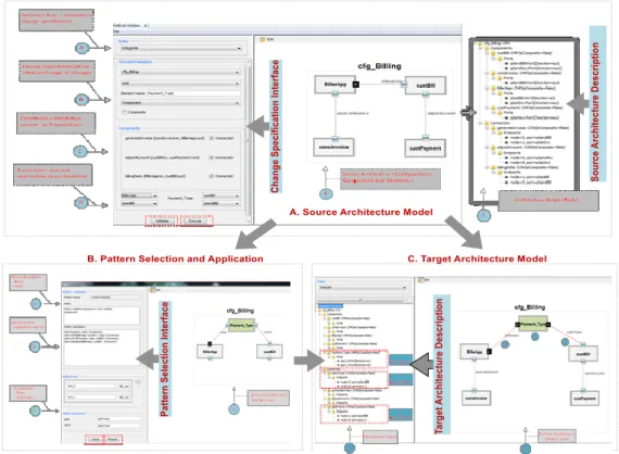
The prototype is presented in Figure 10 with screenshots of its interfaces:
1. Change Specification Interface – allows an architect to declaratively specify the intent of change as the evolution rule (cf. Section VI). An evolution rule explicitly specifies intent of change, the architecture models to be evolved, i.e., source architecture and preconditions of the architecture model.In the functional context of PatEvol, evolution rules are specified in GML (cf. Section VI).
2. Architectural Descriptions – are provided with a graph-based notation (GML) [20]. Architectural descriptions before and after evolution are verified with pre-/postconditions to ensure structural integrity of the architecture is preserved.
3. Pattern Selection and Application – Patterns are expressed in the language as a nested graph. Pattern selection is enabled with design space analysis based on the QOC methodology [16] (cf. Section VI).
We already illustrated pattern-driven evolution reuse to address architecture evolution scenarios for the EBPP case study in Section VI. The objective istoevaluate the solution’s
capability to support reuse-driven change execution by means of change patterns. We claim that, if architecture changes could be specified declaratively, pattern collection in the language abstract complex operational details to enable
generic, reusable,off-the-shelf change execution.
The prototype (PatEvol) assists the user to specify and execute pattern-based changes with appropriate parameterisation and customisation of the process as presented in Figure 10. In Figure 10, we illustrate integration of a mediator type component with directly connected components as the evolution scenario (ES1, cf. Table 1.). More specifically, the prototype interface allows the user to specify the i) intent of change, ii) architecture elements in the source model (to be added, removed or modified) and iii) preconditions on the source architecture model. The prototype enables selection and application of reusable change execution by abstracting complex operational details and architectural constraints. In addition, the tool support also ensures that structural integrity and composition hierarchy of CBSA model is preserved during and after change execution.
B. Preliminary Evaluations
The overall solution requires evaluation of i) pattern discovery
(change mining process) as well as ii) Pattern selection and
pattern application (change execution process). Since technical details about pattern discovery are beyond the scope of this paper, an evaluation of algorithmic complexity and pattern validation is detailed in [14, 15].
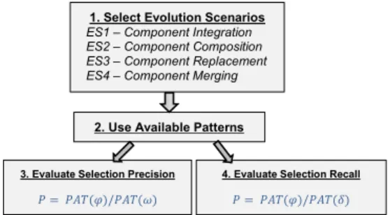
– Experimental Setup to Evaluate Pattern Selection: We summarise the details of the experimental evaluation regarding the precision and recall of the pattern selection below. Evolution Scenarios are selected from Table 1 identified using ALMA [23]. The universal search space for pattern selection is represented as pattern language comprising of a total of 7 change patterns and 2 variants (Figure 3).
Evaluation Objective: to assess the adequacy of solution in supporting pattern selection in given evolution context. We represent pattern selection precision and selection recall criteria. – Pattern Selection Precision (P) is defined as number of
relevant pattern instances retrieved by a search divided by the total number of pattern instances retrieved.
–Pattern Selection Recall (R) is defined as number of relevant pattern instances retrieved by a search divided by the
total number of existing relevant pattern instances . Summary of Results: Based on the formula above, a summary graph of precision and recall is presented in Figure 11. Please note that due to a smaller search space (7 patterns and 2 variants) the recall is measured to be 0.99 approx. for all pattern instances. A high recall suggests the solution is adequate in selecting the most relevant instances from available collection. However, we experience a different behavior for precision, because identification of the exact pattern in the context of related patterns is more challenging. The corresponding values for selection precision fluctuate between 0.33 and 0.99. Whenever we query for “component integration pattern”, we are returned with at least three pattern instances (Component Mediation, Parallel Mediation, and Co-related Mediation).
Figure 10. Precision and Recall for Pattern Selection. We can generalise that in the context of related patterns, the solution is limited in selecting all related patterns instead of the most appropriate one. On the contrary, a pattern instance with no or minimal related patterns is subject to precise selection.
Threats to Validity of Pattern-based Evolution - the accuracy of pattern selection only reflects on the solution capability to assist
and relieve an architect to retrieve the most appropriate patterns in a given evolution context. However, in the future, we will look into a more rigorous validation by involving the software architect/designers to utilise the prototype to execute evolution scenario by accommodating more case studies. We also need to validate prototype-usage followed by expert opinion with a series of questionnaires for a more objective evaluation of solution adequacy.
C. The Notion of Change Anti-Patterns
The role of the pattern language is central in promoting patterns to achieve reuse and consistency in evolution for CBSA. However, change pattern do not guarantee an optimal solution to a given evolution problem, instead they support an alternative and reusable solution. Structural and semantic consistency of CBSA [3, 4] model may be violated as a consequence of pattern-based evolution. These counter-productive and negative impacts of change patterns on architecture model results in change anti-patterns. A detailed discussion about potential anti-patterns is beyond the scope of this paper. However, we believe highlighting the issue is vital to elaborate on some of the identified anti-patterns and possibly prevent them to ensure CBSA model consistency. We discuss two identified anti-patterns and possible prevention in Figure 11.
Anti-pattern I – Orphan Child - As illustrated in Figure 11 a), an orphan child is an anti-pattern as a consequence of removing the composite component having an internal architecture. This means removal of the composite parent component creates orphan children (internal sub-component: ChildX and ChildY). An orphan
component cannot co-ordinate with others in the architecture.
Prevention 1 – Whenever a parent is removed, all of its children must be removed (i.e., remove the child if parent is dead).
Prevention 2 – Apply the Child Adoption pattern to accommodate an orphan (i.e., adopt the child if parent is dead).
Figure 11. An Overview of Preventing Change Anti-patterns.
Anti-pattern II – Bulky Component - As illustrated in Figure 11 b), bulky component is an anti-pattern that results as a consequence of component composition that has a complex and monolithic internal architecture. A composite component (Parent) comprises a bulk of child components (A, B, C) in Figure 11 b).
Prevention – Apply the Functional Slicing pattern to split the parent into fine-grained and specialised components, Figure 11b).
VIII.RELATED RESEARCH
We conducted two systematic literature reviews (SLRs) to classify and compare the existing research that enables or enhances an explicit reuse of knowledge to support architecture evolution [9, 10]. We observed that (in the last decade) evolution styles [4, 5, 8] and change patterns [6, 7, 11, 12, 14] emerged as
0 0.2 0.4 0.6 0.8 1 1.2 CM FS FU AD CC CA CS Selection Precision Selection Recall CM = Component Mediation FS = Functional Slicing FU = Functional Unification AD = Active Displacement CC = Child Creation CA = Child Adoption CS = Child Swap
1. Select Evolution Scenarios ES1 – Component Integration ES2 – Component Composition ES3 – Component Replacement ES4 – Component Merging
2. Use Available Patterns
3. Evaluate Selection Precision
4. Evaluate Selection Recall
![Table 1. Selection, Evaluation and Interpretation of Evolution Scenarios with guidelines in ALMA [2].](https://thumb-us.123doks.com/thumbv2/123dok_us/613864.2573573/9.918.106.811.146.464/table-selection-evaluation-interpretation-evolution-scenarios-guidelines-alma.webp)
![Figure 8: Pattern-Driven Architecture Evolution Using Graph-Transformation (DPO Approach [26]](https://thumb-us.123doks.com/thumbv2/123dok_us/613864.2573573/11.918.199.721.87.418/figure-pattern-driven-architecture-evolution-using-transformation-approach.webp)
![Table 2. A Comparison Summary of Proposed Solution (PatEvol) with State-of-the-Research We summarise our finding from [10] to highlight a) existing](https://thumb-us.123doks.com/thumbv2/123dok_us/613864.2573573/14.918.68.859.102.170/comparison-summary-proposed-solution-patevol-research-summarise-highlight.webp)
