Keio University Master’s Thesis Academic Year 2003
GGCAST A Location Based Multicast
-Keio University Graduate School of Media and Governance
Koshiro Mitsuya
GGCAST A Location Based Multicast
-Summary
Geographic Grouping Multicast (GGCAST) is a new one-to-many com-munication method in which receivers are determined by their geographic positions. Applications of GGCAST include dissemination of traffic infor-mation within relevant locations, such as passing the cause of a traffic jam to cars running behind. The objective of this research is to propose the architecture of GGCAST for a mobile ubiquitous computing environment.
Since, in GGCAST, a multicast group is defined by geographic domain, its membership changes dynamically, and it is difficult to keep a logical mul-ticast tree for data delivery. The fundamental propositions of this research are dynamic group membership and efficient data transmission in such a multicast group.
In this paper, GGCAST is proposed as an application layer multicast (ALM) using a peer-to-peer (P2P) lookup algorithm with a location based service directory. In the targeted environment, nodes are freely moving over several ISPs. This makes ALM to be more suitable for the situation because it doesn’t need a network layer protocol support. In GGCAST, members of a multicast group construct a overlay network using routing information of a P2P lookup algorithm, and a logical multicast tree is built on the overlay network. A member is discovered with the location based service directory as an initial node of the overlay network. The overlay network is using Chord [1], a P2P lookup algorithm. The routing information of Chord has little influence on the overlay network even when a node fails. Because membership of GGCAST changes frequently, the robustness is important.
GGCAST has been implemented as an ITS-related application for eval-uation. It has been confirmed that our directory server can process about 2,000 queries per second. It is estimated that about 4,000 servers would be sufficient to provide a globally available version of this directory service. Other results include that even in a case in which membership changes every 0.9 seconds, over 99% of the members can receive the multicast delivery of information. We conclude that GGCAST realizes a practical location-based multicast.
Keywords:
location based multicast, dynamic group membership, peer-to-peer network, ubiquitous computing, ITS
修士論文要旨2003年度(平成15年度)
GGCAST A Location Based Multicast
-論文要旨
Geographic Grouping Multicast (GGCAST)は、受信者が地理位置情報
によって選択される1対多型のコミュニケーションである。サービス例とし て、後続の車に渋滞の原因を伝えるアプリケーションが挙げられる。本研究 の目的は、モバイルユビキタス環境下の地理位置情報に基づいたマルチキャ ストであるGGCAST を提案することである。 地理位置情報によってマルチキャストグループが定義されるので、受信 者が動的に変化する。そのため、マルチキャストのための論理経路パスを維 持することが難しい。したがって、本研究における主題は、動的なグループ メンバ管理とそのグループ内での効率的なデータ配送である。 GGCASTは、地理位置情報に基づいたサービスを発見するためのディレ クトリサービスとP2Pコンテンツ発見アルゴリズムを用いたアプリケーショ ン層マルチキャスト(ALM)から構成される。想定環境では、ノードは複数 のISP間を自由に移動する。ALMはネットワーク層プロトコルの対応が不 要であるので、想定環境で利用するのに適している。GGCASTでは、マル チキャストグループ内のメンバ同士がP2Pコンテンツ発見アルゴリズムによ る経路情報を用いてオーバレイネットワークを形成する。そして、そのオー バレイネットワーク上にマルチキャストのための論理経路パスが構築される。 この際、オーバレイネットワークに参加するための初期ノードは、提案する ディレクトサービスを利用して発見される。なお、メンバの動的な変化に対 して強いChordアルゴリズム[1]をP2Pコンテンツ発見アルゴリズムとして を利用した。 GGCASTはITS関連アプリケーションとして評価を行った。評価実装を 用いて測定した結果、ディレクトリサーバは毎秒2000クエリ程度を処理で きることが確認された。また、4000台程度のサーバを用意すれば、世界中で このディレクトリサービスが利用できることが算出された。また、0.9秒毎 にメンバが変化するような状態でも、メンバの99%以上がマルチキャスト 配送を受信できることが確認された。したがって、GGCASTを用いて、地 理位置情報に基づいたマルチキャストが実現できることが分かった。 キーワード: 地理位置情報に基づいたマルチキャストグルーピング、動的メンバ 管理、ピアツーピアネットワーク、ユビキタスコンピューティング、ITS 慶應義塾大学大学院 政策・メディア研究科 三屋光史朗
I would like to thank my thesis supervisors, Professor Jun Murai, Profes-sor Hideki Sunahara (Nara Institute of Science and Technology) and Asso-ciate Professor Hiroyuki Kusumoto for their guidance and advice throughout the process of writing this thesis. I am also grateful to Associate Professor Osamu Nakamura. He always gave me insights to this research and guided me to write the thesis in a more appropriate manner. This thesis benefits greatly from his insights, suggestions, and patient revisions.
I would like to thank Dr. Kenjiro Cho (Sony CSL, Inc.), Dr. Keisuke Uehara, Dr. Kazunori Sugiura, Dr. Noriyuki Shigechika, Dr. Yasuhito Watanabe, Masaki Minami, Yuji Sekiya (The University of Tokyo), Ryuji Wakikawa, Shinta Sugimoto (Ericsson Japan, Inc.), Yasuhiro Ohara and Masaaki Sato for their enduring support and guidance. They have always took great care of me in learning from the time I first enrolled into this laboratory. Their efforts have routed me to today’s activity.
A huge thanks to all the members of the Internet Research Laboratory for making work a lot of fun. I am especially grateful to Dr. Thierry Ernst, Kenji Saito, Susumu Koshiba, Masafumi Watari, Koji Okada and Hiroki Matsutani for providing support and insight while I was writing my thesis.
Thanks also to my colleagues (past and present) for their daily assis-tance and encouragement. I greatly enjoyed working with them, and I will, especially, miss Tetsuji Hino, Gen Kobatake, and Keita Miyajima. I also would like to thank Kotaro Kataoka, Takashi Shimizu, Shun Hirose, Hiroaki Takahashi, Daisuke Naruse, Kazuki Hashimoto and Yohei Tanioka.
I would also like to thank Bakery & Restaurant Kinoko, New Orleans and Bar Kaito. They have enhanced the pleasure of not only the table but also my living.
Lastly, and most importantly, I would like to thank my family for every-thing.
Contents
1 Introduction 1 1.1 Background . . . 1 1.2 Fundamental Propositions . . . 2 1.3 Objective . . . 3 1.4 Organization . . . 3 2 Targeted Environment 4 2.1 Mobile Ubiquitous Computing . . . 42.2 Practical Use of Position Information . . . 6
2.3 Summary . . . 8
3 GGCAST Architecture 9 3.1 Approach . . . 9
3.2 Architecture Overview . . . 12
3.2.1 Group Management Scheme . . . 13
3.2.2 Multicasting Scheme . . . 13
3.2.3 Time Line of GGCAST . . . 13
3.3 Scenario : Providing Traffic Information to Cars Running Behind 15 3.4 Summary . . . 16
4 Related Works 17 4.1 IP Multicast . . . 17
4.2 Application Level Multicast . . . 19
4.3 Location Based Multicast in Geocasting . . . 20
4.4 Summary . . . 22
5 Design 24 5.1 Overview . . . 24
5.1.1 Location Based Service Directory . . . 25
5.1.2 Overlay Network Construction . . . 25
5.2 The Location Based Service Discovery Algorithm . . . 27
5.2.1 Overview . . . 27
5.2.2 Keys and Values . . . 28
5.2.3 Load Balancing . . . 28
5.2.4 The method to specify a multicast region . . . 29
5.2.5 Data Location and Lookup Algorithm . . . 30
5.3 Overlay Network Construction . . . 31
5.3.1 Overview . . . 31
5.3.2 Dynamic Operations . . . 32
5.3.3 Robustness . . . 32
5.3.4 Multiple registration of pointers to the multicast group 33 5.4 Summary . . . 33 6 Implementation 34 6.1 Overview . . . 34 6.2 Library . . . 36 6.3 Variables . . . 37 6.4 User interface . . . 38 6.4.1 Directory Service . . . 38 6.4.2 Multicast Service . . . 38 7 Evaluation 42 7.1 Group Search Performance . . . 42
7.1.1 Experiment 1: Database Lookup . . . 43
7.1.2 Experiment 2: Query Processing . . . 44
7.1.3 Conclusion . . . 44
7.2 Required Number of Directory Servers . . . 45
7.3 Modeling of Dynamic Group Memberships . . . 47
7.4 Robustness of the Overlay Network . . . 48
7.4.1 Experiment 3: Overlay Network Construction . . . 48
7.4.2 Topology . . . 49
7.4.3 The number of connections . . . 49
7.5 Summary . . . 53
8 Conclusion and Future Works 54 8.1 Conclusion . . . 54
8.2 Status and Future Directions . . . 55 A Current Position Sensing Technologies 56
CONTENTS
B The Chord Protocol 61
B.1 Overview . . . 61
B.2 Consistent Hashing . . . 62
B.2.1 Simple Key Location . . . 64
B.2.2 Scalable Key Location . . . 64
2.1 Changes in number of cellular phone with and without Internet
access function in Japan . . . 5
2.2 Total number of the car navigation systems shipped per year in Japan (c)JEITA . . . 7
2.3 Targeted Environment . . . 8
3.1 Multicast grouping with position information . . . 10
3.2 GGCAST Architecture . . . 12
3.3 Multicast Routing in a multicast group: . . . 13
3.4 Time Line of GGCAST . . . 14
3.5 Application example: Providing traffic information to cars be-hind . . . 15
4.1 Example 2-d coordinate overlay with 5 nodes . . . 20
4.2 Location Based Multicast in Geocasting . . . 22
5.1 GGCAST using Hierarchical P2P System . . . 25
5.2 Overview of The Location Based Service Directory . . . 27
5.3 Maps which stores the location information of a multicast group 29 5.4 array for each point . . . 30
5.5 scalable search for the array . . . 31
5.6 Affection when a node has failed . . . 33
6.1 GGCAST Implementation Modules . . . 35
6.2 Running Directory Service . . . 38
6.3 Starting a bootstrap node . . . 39
6.4 Starting additional nodes . . . 39
6.5 Running multicast server . . . 39
LIST OF FIGURES
6.10 Receiving datagram . . . 41
7.1 Search flow by using distribution tree model and ring model . 43 7.2 Experiment to measure the lookup performance . . . 44
7.3 Lookup performance at a server . . . 45
7.4 Experiment to measure the query processing performance . . . 46
7.5 Processing Performance at a server . . . 47
7.6 Topology of a overlay network . . . 50
7.7 Number of virtual connections . . . 51
7.8 Rate of reachable nodes . . . 52
B.1 An identifier circle (ring) consisting of 10 nodes storing five keys 62 B.2 (a)Simple(but slow) pseudocode to find the successor node of an identifier id. Remote procedure calls and variable lookups are proceeded by the remote node. (b)The path taken by a query from node 8 for key 54, using the pseudocode in (a) . . 65
B.3 (a)The finger table entries for node 8. (b) The path a query for key 54 starting at node 8, using the algorithm in Figure ?? 66 B.4 Scalable key lookup using the finger table . . . 66
B.5 Pseudocode for stabilization . . . 68
B.6 Example illustrating the join operation. Node 26 joins the system between nodes 21 and 32. The arcs represent the suc-cessor relationship. (a) Initial state: node 21 points to node 32; (b) node 26 finds its successor (i.e. node32) and points to it; (c) node 26 copies all keys less than 26 from 32; (d) the stabilize procedure updates the successor of node 21 to node 26. . . 69
3.1 Explanatory variables in 1.8km-square region . . . 16
4.1 Comparison with other research on application layer multicast 23 5.1 Key and Values of the location based service directory . . . . 28
6.1 The Chord Library . . . 36
6.2 The Directory Library . . . 37
6.3 The Mcast Library . . . 37
7.1 Specification of experiment PC . . . 44
7.2 A query processing performance at a server . . . 46
7.3 Dynamic Group Memberships . . . 48
7.4 Environment variables . . . 49
7.5 Unnecessary Packets . . . 53
A.1 Current Position Sensing Technologies 1 . . . 58
A.2 Current Position Sensing Technologies 2 . . . 59
Chapter 1
Introduction
In this chapter, we introduce the background of this research. First of all, the proposed model called Geographic Grouping Multicast (GGCAST), a loca-tion based multicast, is defined. Next, its importance in real-world situaloca-tions is explained. Then, our objective in this research is described. At last, the organization of this thesis is described.
1.1
Background
A number of applications such as large-scale file distribution, Internet TV, video conferencing and shared white boards [2] [3] [4] [5] require one-to-many message transmission to enable efficient many-to-many communication. Mul-ticast is a communication between a single sender and multiple receivers on a network. Together with anycast and unicast, multicast is one of the com-munication types in the Internet.
Multicast is often used in a situation where an application needs to send the same information to more than one destination. This is because mul-ticasting consumes much less network resources compared to unicasting to each destination. Network resource consumption should be considered with higher importance in the mobile ubiquitous networking environment where mobile hosts communicate with each other over wireless links.
Meanwhile, the needs for mobility support in the Internet has grown significantly in recent days. For example, it is useful to connect mobile hosts such as cars and trains to the Internet and exchange their information freely. Probe Information Service [6] and InternetITS [7] in which our Internet CAR Project [8], have been participating are good examples of such information services.
scattered over many locations. Automobiles are connected to the Internet, providing Internet connectivity to each sensor which acquires information such as location, velocity, and movement of wipers. By collecting infor-mation from such sensors in the automobiles via the Internet, new kind of information, such as knowledge of a traffic congestion or the surrounding weather constructed from collected information, can be obtained.
The derived information is always up-to-date, and is much more detailed than what existing systems can provide. The InternetITS is a concept which uses the Internet as the common ITS infrastructure. ITS (Intelligent Trans-port System) [9] is a system designed to promote the advancement in the car navigation technology to give users more effective driving supports. The Electronic Toll Collection system (ETC) [10] is a good example of driving supports using computer technologies which has reduced the traffic conges-tion on toll-ways by automatically collecting the toll fees. It is expected that several ITS services are achieved efficiently with the common infrastructure based on Internet technologies
In this world, a lot of nodes are connected to the Internet with mobility supports [11] [12] at all time and all places, those mobility supports allow to keep connections alive while hosts or networks are moving around. And they use network resources distributed ubiquitously [13]. We call this mobile ubiquitous computing environment.
1.2
Fundamental Propositions
In order to achieve multicasting, it is required to find some way to define a multicast group. In conventional multicasting algorithms [14], a multicast group is considered as a collection of hosts which register to the group. In order to receive multicast messages, a node must first join a particular group. A distribution tree rooted at a traffic source is constructed within the group members. When a host sends a message to the multicast group, it just sends the message to the IP address representing the group. The message is delivered according to the tree. All the group members then receive the message.
Geographic Grouping Multicast (GGCAST), a location based multicast, is one of one-to-many communication in which receivers, members of a mul-ticast group, are determined by their geographical positions. Its applica-tions include advertising regional information to travelers or telling the cause of a traffic jam to cars running behind. One of the interesting feature of
CHAPTER 1. INTRODUCTION
Since a member changes dynamically, this makes it difficult to maintain the distribution tree for data delivery.
The fundamental propositions of this research are the architecture to achieve the following:
• Dynamic group membership
• Efficient data transmission in the multicast group
1.3
Objective
Geographic Grouping Multicast (GGCAST) is one of one-to-many communi-cation which members of a multicast group are determined with geographical position information. The objective of this research is to propose GGCAST, a location based multicast architecture in mobile ubiquitous networking. To our best knowledge, there is no preceding researches in computer networking area. Thus we believe that this research deserves serious attention.
To achieve this objective, we will analyze characteristics of the targeted environment, and discuss appropriate approaches corresponding to the char-acteristics based on the analysis and the opinions of existing works. We propose a new location based multicast model based on one of the discussed approaches, and we simulate the model in different scales for evaluation. The simulation models an actual application in the targeted environment.
1.4
Organization
The targeted environment of this research is described in Chapter 2. In Chapter 3, the appropriate approaches and the GGCAST architecture are discussed. In addition, usage scenarios are introduced to clarify requirements for the system. In Chapter 4, related works of this research are introduced, and the differences from this research are discussed. Chapter 5 describes the detail of GGCAST. Chapter 6 explains our implementation of the model. The model is evaluated by simulations whose conditions and results are discussed in Chapter 7. Chapter 8 addresses the area for future study and concludes the paper.
Targeted Environment
In this chapter, we describe the targeted computing environment. We define our targeted environment as a mobile ubiquitous computing environment. In this world, network resources are ubiquitously distributed, and Internet nodes, e.g. Cars, laptops and PDAs, are always connected, regardless of the changes of their locations and access points to the Internet. Meanwhile, a lot of applications using physical information such as geographical location information will appear.
2.1
Mobile Ubiquitous Computing
Ubiquitous Computing is Coming Up
The word “Ubiquitous” gained a lot of attention recently. The origin of the word means that it’s omnipresent in Latin, which means that it can be used anywhere and anytime. Ubiquitous Computing have applied this concept in the world of computing. Mark Weiser of Xerox PARC research institute ad-vocated this notion in 1989. His paper [13] describes a world where wirelessly networked computers are distributed throughout the environment.
The technology of small information terminals, such as a cellular phone, PHS and PDA, is progressing, and the attention to the ubiquitous computing has greatly gathered in recent years.
Constant Internet Access for Mobile Hosts
As a network for realizing Ubiquitous Computing, wireless technology has a big possibility. A cellular phone is a good example of the wireless
commu-CHAPTER 2. TARGETED ENVIRONMENT
the reason why the cellular phone became popular in our life. Here, mobil-ity means migration support and coverage means the area where service is offered.
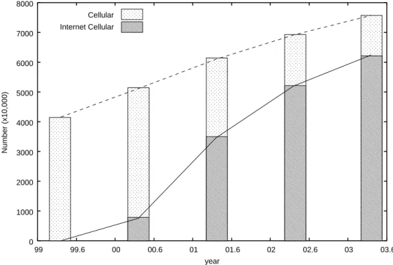
In recent comparison, the ratio of the data communication is increasing by the cellular phone. As Figure 2.1 shows, number of cellular phones which has Internet access function is increasing in Japan [15].
0 1000 2000 3000 4000 5000 6000 7000 8000 99 99.6 00 00.6 01 01.6 02 02.6 03 03.6 Number (x10,000) year Cellular Internet Cellular
Figure 2.1: Changes in number of cellular phone with and without Internet access function in Japan
However, data traffic in the current cellular phone system requires high cost. When transmitting even a small data packet, the system must reserve a circuit to the destination. Thus, the method to build a network infrastructure suitable for data communication becomes a key from now on.
Multimedia Research Institute Corporation propose to fulfill providing the network infrastructure which combines IP technology with TD-CDMA [16]. TD-CDMA [17] is one of the communication systems standardized as IMT-2000 of the third generation cellular phone (3G). TD is an abbreviation for Time Division; uplink/downlink circuit of a communication is segmented by time. Compared to the existing Frequency Division, it is said that affinity with data communication is higher. It is possible to build a very efficient
and simple data communication network by combining IP technology. The bandwidth is expected to be 100Kbps for upload and 1Mbps for download.
In the near future, there will be many wireless hotspots on the streets, offices, trains, resorts and everywhere. These hotspots are assumed to sup-port IP network. Therefore, the mobile hosts ubiquitously distributed in the world can obtain the Internet connectivity anytime and anywhere.
Mobility Supports in IP Networks
Several mobility support protocols are developed to support IP nodes under various situations. Host mobility is for a mobile host to hide movements from the Internet. Mobile IPv6 [11] is designed to support such host mobil-ity and is being standardized at the Internet Engineering Task Force (IETF) [18]. Network Mobility protocol, known as NEMO, conceals movements for a network that moves entirely. NEMO is being discussed at the NEMO work-ing group at IETF [12]. A “mobile ad hoc network” (MANET) is an au-tonomous system of mobile nodes connected by wireless links without a par-ticular infrastructure. Several MANET routing protocols, such as DSR[19], AODV[20], OLSR[21], TDBRPF[22] have been proposed for a MANET with a dynamically changing topology.
With these mobility support protocols, mobile nodes can obtain Internet connectivity just as any fixed nodes. Thus, the changes in communication environment for the mobile nodes are not considered in this paper.
2.2
Practical Use of Position Information
In the future, position information sensing systems will be deployed in ev-ery mobile node. Position information will become an information that is as common as time; receiving input from Global Positioning System [23], when outdoors, and from other position information providing devices, when indoors.
The car navigation system is a well known mobile node using GPS to obtain position information. Figure 2.2 shows the shipping volume of car navigation system in Japan [24]. The graph shows the total number of the car navigation systems shipped in label y and its corresponding year in label x. The estimated volume of shipments of the car navigation systems is 12 billion at 2004 and its volume is increasing year by year.
sys-CHAPTER 2. TARGETED ENVIRONMENT 0 2000000 4000000 6000000 8000000 10000000 12000000 14000000 1997 1998 1999 2000 2001 2002 2003 2004 units year 1902255 2796199 3931365 5352386 7100325 9050027 11476000 12937000
Figure 2.2: Total number of the car navigation systems shipped per year in Japan (c)JEITA
grade maps or to provide route search using the corrected road information from the server. Thus it is expected that many car navigation systems have Internet connectivity soon. This is a example of practical use of position information.
GPS is introduced as a position sensing technology here, however, there are many other position sensing technologies [25]. Details are listed in Ap-pendix A.
As described above, position information can be used wherever even if it is used indoor or outdoor. All devices connected to the Internet - high spec workstations, tiny nodes, and any nodes - use a technology that best matches their use. Thus, it is expected that every mobile computer are connected to the Internet and equip a position information sensing system, they use position information on a routing application.
2.3
Summary
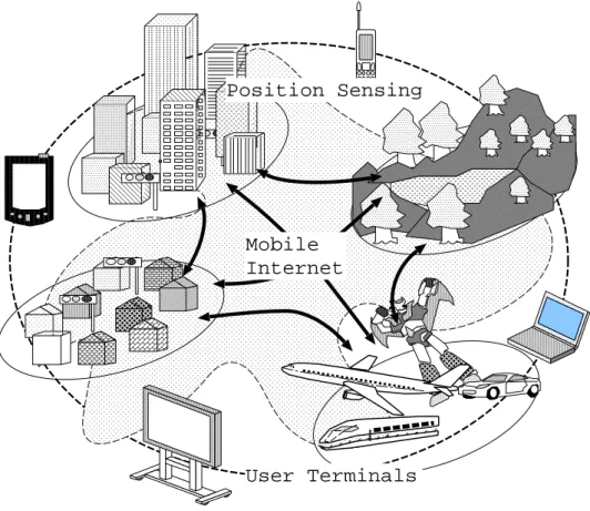
Ubiquitous Computing is coming up. In ubiquitous computing, nodes are connected to the Mobility supported Internet anywhere and anytime. User can access to various Internet services from terminal computers. This world is defined as “Mobile Ubiquitous Computing”. Additionally, position informa-tion can be used whether even if it is used indoor or outdoor. This research targets on this environment (Figure 2.3).
Mobile Internet
User Terminals Position Sensing
Chapter 3
GGCAST Architecture
In this chapter, we describe Geographic Grouping Multicast (GGCAST), a location based multicast architecture. GGCAST is one to many communi-cation model where receivers are selected using geographical position infor-mation. This chapter also describes the scenarios of using GGCAST and describes examples to clarify the requirements for the architecture.
3.1
Approach
Multicasting typically consists of multicast group management scheme and multicast routing. In conventional multicasting algorithms, a multicast group is considered as a collection of nodes which register to that group. For a node to receive any multicast message, it must first join a particular group. A distribution tree rooted at a traffic source is constructed within the group members. When a node send a message to a multicast group, sending the message to the IP address of that multicast group is all it takes. The message is delivered according to the tree, all the group members then receive the message.
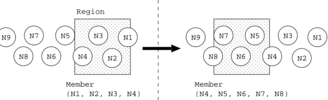
The interesting feature of GGCAST, as shown in Figure 3.1, is that the members in a group change dynamically according to the physical move-ment of the nodes, since the group is formed based on geographic position information.
A doted square in Figure 3.1 represent a multicast region. N1, N2, N3,,,N9 are mobile nodes. First, members are N1, N2, N3 and N4. Because mobile nodes are moving around, the members are changing dynamically; members change to N4, N5, N6, N7 and N8 in the figure.
In order to achieve dynamic group membership, we propose following approaches. Details on each approaches are described in this section.
N1 N2 N3 N4 N5 N6 N7 N8 N9 N1 N2 N3 N4 N5 N6 N7 N8 N9 Region Member (N1, N2, N3, N4) Member (N4, N5, N6, N7, N8)
Figure 3.1: Multicast grouping with position information
• Multicast grouping with geographic information
• Join/Leave model
• End node organization
In order to achieve efficient data transmission in the multicast group, we propose following approaches.
• End node Organization
• Overlay Network which has robustness when a node fails
• Less Impact of Members Failures
• Less Packet Duplication
Multicast Grouping with Geographic Information
With IP Multicast, the group is abstracted as multicast IP address. In order to join the group, a node is required to send requests. A distribution tree rooted at the traffic’s source is constructed based on the request. A single packet transmitted at the source is delivered to an arbitrary number of receivers by replicating the packet within the network at fan-out points, routers, along a distribution tree rooted at the traffic’s source.
A multicast group of GGCAST is determined with geographic informa-tion. Although an address is one method to specify a region of geographic information, the region can simply be specified with longitude and latitude.
CHAPTER 3. GGCAST ARCHITECTURE
Join/Leave Model
It is preferable that only the desired node receives multicast traffic, and not all nodes in the region. Although a model where all nodes receive the traffic is far easier for multicast group management scheme, it is not desirable because the resources on mobile node are limited. Therefore, each node has to decide, actively, which multicasting packet it receives. GGCAST divides the world into a number of regions. Therefore, a kind of directory service is necessary to discover the multicast group currently being offered at a certain point by some methods.
End Node Organization
The nodes in a multicast group are connected to the Internet by various media. For example, cellular, PHSs and Wireless LAN are used; nodes change these medias by situation. Even if we are in the same place, we use cellular phones of different carriers. Thus, nodes may connect with separate ISP, even if each node is in near geographic position.
Due to the fact that communication environment changes accordingly with the ISPs connected, inter-domain operation is difficult in most cases. The system that requires alterations in relay nodes is hard to use. ISP provides only the Internet connectivity. Thus only the end node should realize the GGCAST system.
In addition, members in multicast group should perform themselves, be-cause huge number of groups exists all over the world. Since end node or-ganization dose not concentrate on a center system, it has advantageous in robustness, and load distribution is also realizable.
Less Impact of Member Failures
Since members in a group change dynamically, the system should have a robustness to member failures. When a node leaves or fails from the multicast group, the influence on the system should have less impact.
Less Packet Duplication
Since the bandwidth of mobile nodes is limited, multi-unicast by single node is difficult. Members should relay packets efficiently.
This discussion is going to be about make efficient logical distribution tree for multicast delivery. In order to make “no packet duplicate” tree, high costs, e.g. control packets and route calculation, may be required. However, simple flooding, each node reply to their neighbor, takes long times to finish
the deliver and occurs a lot of packet duplication. This is a tradeoff between the costs and its efficiency.
3.2
Architecture Overview
The proposed GGCAST architecture consists of following two functionalities:
• Group management scheme
• Multicasting scheme
Group management scheme includes a directory service to find pointers to multicast groups with location information as search key, and membership management functions to support dynamic alteration of members. Multicas-ting scheme includes multicast rouMulticas-ting to enable efficient data delivery/copy to reduce network load. The scheme is done by the end nodes, and not concentrated on a centralized system.
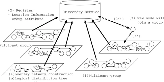
Figure 3.4 shows an overview of location based multicast architecture. The circle represents a node. A multicast group is described as a rectangle in the figure. There is a directory service to discover the multicast group currently offered at a certain place.
Directory Service Node Node Node Node Multicast group (2) Register - Location Information
- Group Attribute (3) New node will
join a group
(3’) (3’’)
Multicast group (1)
(a)overlay network construction (b)logical distribution tree construction
CHAPTER 3. GGCAST ARCHITECTURE
3.2.1
Group Management Scheme
(1) Nodes in a rectangle organize a multicast group. A member of the group offers a multicast service by themselves. (2) Each multicast group registers its geographic positions and an attribute of the multicast group to the directory. A sender node performs the registration. (3) A node discovers a multicast group by using the directory service, and joins the multicast group.
3.2.2
Multicasting Scheme
The multicasting scheme consists of overlay network construction and mul-ticast routing on the overlay network. The members of a mulmul-ticast group self-organize into an essentially random application-level mesh topology (a). A multicast routing algorithm is used over the topology to construct distri-bution trees rooted at each possible traffic source (b).
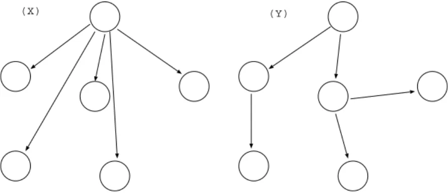
Figure 3.3 shows multicast routing in a multicast group. The circle rep-resent a node. The arrow shows data flow.
(X) (Y)
Figure 3.3: Multicast Routing in a multicast group:
Since the bandwidth of mobile nodes is limited, (X) multi-unicast by sin-gle node is difficult. It is desirable that the transmitting may be suboptimal (Y).
The propositions in the operation are how to organize overlay network which can be scalable in mobile ubiquitous environment and efficient data-gram delivery with saving network resources.
3.2.3
Time Line of GGCAST
In order to figure out the relation between group management scheme and multicasting scheme, we describe the time line of location based multicast.
Figure 3.4 shows the fundamental time line of the proposed model. The figure shows a multicast group which consists of sender and receivers. Directory in the figure shows a directory service to find a multicast group, and N1, N2 and N3 indicate nodes.
Directory N1 N2 N3 (1) (2) (3) (4) (5) (6) (7) (8)
End host multicasting Group Finding
Figure 3.4: Time Line of GGCAST
N1 creates a new multicast group. (1) N1 registers the group to the directory with IP address, port number, the region and description. (2) N2 determines multicast group which serves a point included the region. (3) The directory answers the group created by N1 before. (4) N2 joins the multicast group according to a protocol of the group, members of the group are organizing an overlay network, with IP address and port number which answered by the directory as initial pointer. (5) N3 also determines multicast group which serves a point included the region. (6) The directory answers the group created by N1. (7) N3 joins the multicast group according to a manner of the group. (8) N1 sends data gram to the group, it is delivered by a flooding scheme.
CHAPTER 3. GGCAST ARCHITECTURE
3.3
Scenario : Providing Traffic Information
to Cars Running Behind
A possible application of GGCAST is providing traffic information to cars running behind. Traditionally, hazard lights are used to inform the traffic jam to following vehicles. Although the drivers behind don’t know, exactly, what has happened, but they could know that something has happened in front. Thus a method of obtaining more detailed information is very convenient.
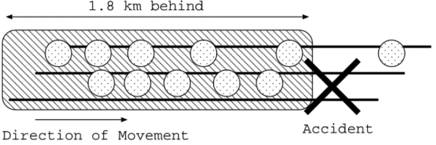
Figure 3.5 shows a situation of this application. The circle represents a car, the two lines express a road. There is an accident in the direction of cars movement.
Direction of Movement Accident 1.8 km behind
Figure 3.5: Application example: Providing traffic information to cars behind
A node creates a multicast group to tell the cause of this accident to cars 1.8km behind. Then, the multicast region is 1.8 km from the accident point, and the description of this multicast group might be “TRAFFIC JAM”. Other nodes check multicast groups serving near themselves. The nodes can know there is the multicast group in their direction of movement by using the directory service. The directory also returns a pointer to the multicast group, nodes can join the group via the pointer. When nodes join to the group, nodes receive the information about this traffic jam. Nodes will leave the group when they pass the accident point.
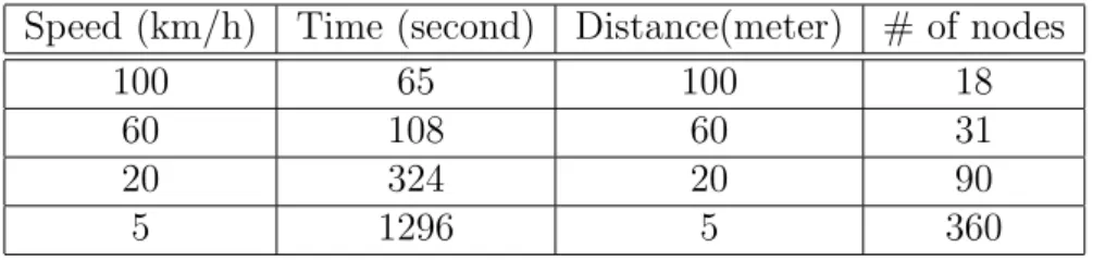
When 1.8km squares region created from a accident point, the explana-tory variables is estimated as Table 3.1. The multicast region is 1.8 km square from the accident point. Speed is means of node’s speed (km/h), and Time is a time a node goes through the region. Depending on the Distance (meter) between the cars, number of nodes in the region is estimated as # of nodes.
“Speeds” as described in the table consider following situations. 100km/h is for highway, 60km/h for driving smoothly on streets in outskirts, 20km/h
Table 3.1: Explanatory variables in 1.8km-square region Speed (km/h) Time (second) Distance(meter) # of nodes
100 65 100 18
60 108 60 31
20 324 20 90
5 1296 5 360
for the streets in downtown, and 5km/h for traffic jam situations. A space between two cars is generally defined as 1/1000 of its speed.
From this estimation, following requirements about its performance are figured. When a traffic jam occurs;
• Number of node in the group is about 360.
• A node stays at the group about 1300 second.
• A node newly joins and leaves to the group per 5m/(5000m/h) = 3.6 seconds
3.4
Summary
GGCAST architecture consists of group management scheme and multicas-ting scheme. Group management scheme includes a directory service to find pointers for multicast groups with a location information as keys, and sup-port dynamic membership. Multicasting scheme consists of overlay network construction and multicast routing.
The following items are functional requirements for the GGCAST system. 1. Dynamic group membership
2. Directory service to discover a multicast group 3. Multicast routing realized by only end node. 4. No concentrate on a center system
Chapter 4
Related Works
In this chapter, we explain related works of this research. IP Multicast is a widely accepted concept of multicast on the Internet. However, IP multicast has many fundamental issues, inherent in its original architecture, which need to be changed in order to implement GGCAST. Application Layer Multicast has argued as a more practical alternative to IP multicast, citing the end-to-end argument. To ensure better scalability, dynamic grouping and network fail-safe, application layer multicast has been implemented using peer-to-peer routing algorithms. We focus mainly on this application layer multicast in this thesis. We also describe differences between our GGCAST, a location based multicast, and other model called “location based multicast”.
4.1
IP Multicast
The IP Multicast service [14] was proposed as an extension to the Internet architecture to support efficient multi-point delivery at the network level. With IP Multicast, a single packet transmitted at the source is delivered to an arbitrary number of receivers by replicating the packet within the network at fanout points, routers, along a distribution tree rooted at the traffic’s source.
In his seminal work in 1989 [14], Deering argues that this second consider-ation should prevail and multicast should be implemented at IP layer. This view so far has been widely accepted. IP Multicast is the first significant feature that has been added to the IP layer since its original design and most routers today implement IP Multicast.
IP Multicast has been studied for many years now. Yet, IP multicast de-ployment has been slowed by difficult issues related to scalable inter-domain routing protocols, charging models, robust congestion control schemes and
so forth [26] [27] [28].
IP Multicast has several drawbacks that have so far prevented the service from being widely deployed. First, IP Multicast requires routers to main-tain per group state, which not only violates the “stateless” architectural principle of the original design, but also introduces high complexity and se-rious scaling constraints at the IP layer. Second, the current IP Multicast model allows for an arbitrary source to send data to an arbitrary group. This makes the network vulnerable to flooding attacks by malicious sources, and complicates network management and provisioning. Third, IP Multicast re-quires every group to dynamically obtain a globally unique address from the multicast address space and it is difficult to ensure this in a scalable, dis-tributed and consistent fashion. Fourth, IP Multicast is a best effort service. Providing higher level features such as reliability, congestion control, flow control, and security has been shown to be more difficult than in the unicast case. Finally, IP Multicast calls for changes at the infra-structural level, and this slows down the pace of deployment. While there have been attempts to partially address some of the issues at the IP layer [29] [30], fundamental concerns “stateful” architecture of IP Multicast and support for higher layer functionality have remained unresolved. Following it the above summary, several drawbacks of IP multicast.
• IP Multicast requires routers to maintain per group state.
• IP multicast model allows for an arbitrary source to send data to an arbitrary group.
• IP Multicast requires every group to dynamically obtain a globally unique address.
• IP multicast is a best effort service.
• IP Multicast calls for changes at the infra-structural level.
When implementing GGCAST on IP multicast, we face on other prob-lems additionally. First, IP multicast itself has no functionality to assign a multicast address to the location based group. In IP multicast, every group obtain a multicast address, a globally unique address. The address typically assigned manually by administrators. Since there are large number of multi-cast groups in the world, the management of multimulti-cast addresses is difficult. Second, IP multicast is not necessarily effective. A comparatively few
num-CHAPTER 4. RELATED WORKS
• No functionality to assign a multicast address.
• Not necessarily effective in mobile ubiquitous networking. For the above reasons, IP Multicast is not suitable for GGCAST.
4.2
Application Level Multicast
Because of the problems facing the deployment of a network level multi-cast service as described at previous section, many recent research proposals have argued for an application level multicast service [26] [27] [31] and have described designs for such a service and its applications.
The majority of these proposed solutions (for example [27], [31] and Re-layCast [32]) typically involve having the members of a multicast group self-organize into an essentially random application level mesh topology. In order to construct distribution trees rooted at each possible traffic source, a tra-ditional multicast routing algorithm, such as DVMRP [14], is used over the topology.
Such routing algorithms require every node to periodically announce its estimated distance from every possible destination to its local neighbors and hence every node maintains state for every other node in the topology. Fur-ther, in the case of a change in the topology, every node must learn about this change and update its routing table if required. Hence, although these proposed solutions are well suited to their targeted applications, their use of global routing algorithm limits their ability to scale to large (more then a thousand nodes) group sizes and to operate under conditions of dynamic group membership.
To ensure better scalability and handling of dynamic groups and network failures, application level multicast has been implemented using peer-to-peer routing algorithms. For example, Bayeux [33] is implemented on top of Tapestry, and organizes multicast receivers into a distribution tree routed at the source. In Bayeux, nodes explicitly join and leave a multicast session by notifying the source node. The service model is limited to a single source. SelectCast [34] is a peer-to-peer publish/subscribe routing service, built on Astrolabe, a peer-to-peer domain aggregation service. Both SelectCast and Astrolabe are heterogeneity-aware, but at the cost of some increased management overhead when compared to other peer-to-peer protocols. Al-though these services do not rely on any special-purpose servers, they can leverage asymmetries between hosts and between network connections. Se-lectCast is also restricting the service model to a single traffic source.
[35] has proposed an application level multicast scheme capable of scal-ing to large group sizes without restrictscal-ing the service model to a sscal-ingle source. Their scheme leverages recent work on Content-Addressable Net-works (CANs) [36]. Briefly, a Content-Addressable Network is an application-level network whose constituent nodes can be thought of as forming a virtual d-dimensional Cartesian coordinate space. Every node is a CAN “owns” a portion of the total space. For example, Figure 4.1 shows a 2-dimensional CAN occupied by 5 nodes. A CAN is scalable, fault-tolerant and completely distributed. Such CANs are useful for a range of distributed applications and services. For example, in [35] they focus on the use of a CAN to provide hash table-like functionality on Internet-like scales - a function useful for in-dexing in peer-to-peer applications, large-scale storage management system, the construction of wide-area name resolution services and so forth.
A B
C D E
0.0 1.0
1.0
Node’s virtual coordinate zone A(0-0.5,0-0.5)
B(05.-1.0,0.0-0.5) C(0.0-0.5,0.5-1.0) D(0.5-0.75,0.5-1.0) E(0.75-1.0,0.5-1.0)
Figure 4.1: Example 2-d coordinate overlay with 5 nodes
Table 4.1 shows comparisons with another researches on application layer multicast. This paper looks into the question of how the deployment of such P2P distributed infrastructures might be utilized to support multicast ser-vices and application. We outline the design of an application level multicast scheme built using a Chord routing algorithm. Our design shows that ex-tending the Chord framework to support multicast comes at trivial additional cost in terms of complexity and added protocol mechanism. A key feature of our scheme is that because we exploit the well-defined structured nature of Chord topologies we can eliminate the need for a multicast routing algo-rithm to construct distribution trees. This allows our Chord-based multicast scheme to scale to large group size.
CHAPTER 4. RELATED WORKS
graphical information. The location based multicast algorithms, geocasting, is delivered to the set of nodes within a specified geographical area. That indicates another meaning as we focus on location based multicast. Unlike the traditional multicast schemes, the multicast group (or geocast group) is implicitly defined as the set of nodes within a specified area. The set of nodes in the multicast region is the location based multicast group.
[38] discussed the problem of geocasting - broadcasting to every node in a specified geographical area- in mobile ad hoc environments. In [38], the specified geographical area is called the multicast region, and the set of nodes that reside within the specified multicast region is called a location-based multicast group. They propose two location-based multicast algorithms in geocasting. The proposed algorithms limit the forwarding space for a mul-ticast packet to the so-called forwarding zone. Simulation results indicate that proposed algorithms result in lower message delivery overhead, as com-pared to multicast flooding. As simulation results show, while reducing the message overhead significantly, it is possible to achieve accuracy of multicast delivery comparable with multicast flooding. They also discuss how the basic location-based multicast schemes may be optimized to improve performance. As evaluation of these traditional multicast algorithms shows, it is possible to implement a location-based multicast by maintaining a multicast tree. A comparison between the algorithms presented in this paper and the alter-native approach of maintaining a multicast tree is also a topic for further work.
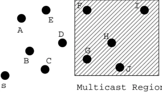
Consider a node S that needs to multicast a message to all nodes that are currently located within a certain geographical region. This specific area is the “Multicast Region”. The multicast region would be represented by some closed polygon such as a circle or a rectangle(see Figure 4.2). Assume that node S multicasts a data packet at timet0, and three nodes (X, Y and Z) are located within the multicast region at that time. Then, the multicast group, from the viewpoint of node S at time t0, would be have three members that are expected to receive the multicast data packet sent by node S. Accuracy of multicast delivery can be defined as ratio of the number of group members that actually receive the multicast packet, and the number of group members which were in the multicast region at the time when the multicast is initiated. For example, if only node X among three members of the multicast group actually gets a multicast packet, accuracy of delivery for the multicast packet will be 33.33%.
s A B C D E F G H I J Multicast Region
Figure 4.2: Location Based Multicast in Geocasting
4.4
Summary
In mobile ubiquitous networking, nodes are freely moving over several do-mains, thus IP multicast is not necessarily effective. In contrast, application layer multicast is recognized for the fact that it does not require network layer multicast protocol.
Otherwise, application layer multicasts using a peer-to-peer routing al-gorithm have been proposed to ensure better scalability and handling of dynamic groups and network failures. In this paper, we propose a applica-tion layer multicast using the Chord routing algorithm with a locaapplica-tion based service directory.
CHAPTER 4. RELATED WORKS
Table 4.1: Comparison with other research on application layer multicast
End host discovery Overlay network construction
multicast routing
Relay Cast
N/A. They assume that nodes know the rendezvous points.
Everyone maintains state for every oth-ers, the topology is optimized with Met-ric.
DVMRP or PIM-SM/CBT or Shortest widest path algo-rithm.
Select Cast
Everyone knows the root domain’s router.
Hosts are organized in a domain hierar-chy, and each domain has a set of attribute. every nodes maintain state of every others.
distribution tree rooted at the root domain’s router. Senders specify the set of intended destination hosts through the use of SQL condition. CAN based appli-cation layer multi-cast
A CAN has an asso-ciated DNS domain name, and that this resolves to the IP address of one or more CAN bootstrap nodes.
A node maintains the IP addresses of its neighbor that hold coordinate zones adjoining its own zone.
Flooding based on CAN routing table.
Bayeux N/A. They assume that nodes know at least one node par-ticipating the net-work.
Each node maintains a number of neigh-bors with a common matching prefix.
They organize mul-ticast receivers into a distribution tree routed at the source
Design
In this chapter, we discuss the details of GGCAST. We describe the overview of our design first, an application layer multicast using a peer-to-peer lookup algorithm and combined with a location based service directory. Next, the details of each function is discussed.
5.1
Overview
Geographic Group Multicast (GGCAST) consists of two-level hierarchical peer-to-peer (P2P) overlay networks. The upper overlay network is a di-rectory to find a multicast group. The lower overlay network constructs an application layer multicast (ALM) service.
The overview of GGCAST is shown in Figure 5.1. The circle represent a node in the multicast group. The double circle shows a server which organize the directory.
A GGCAST multicast group determined by geographic positions orga-nizes an overlay network to construct a logical multicast tree. Nodes use this directory to find the pointer to the group in which they decide to join.
ALM typically consists of end host discovery, overlay network construc-tion and multicast routing. In GGCAST, member of a multicast group con-struct a overlay network by using the Chord lookup algorithm [1], and a log-ical multicast tree for data delivery is built on the overlay network. A node finds a member of the overlay network as the initial pointer to the group from a location based service directory. For the detail of Chord lookup algorithm, refer to [?].
CHAPTER 5. DESIGN Multicast Service Directory Service lookup/register Overlay network constraction multicast tree constraction
Figure 5.1: GGCAST using Hierarchical P2P System
• Overlay network construction using Chord lookup information
• Flooding on the overlay network
5.1.1
Location Based Service Directory
The location based service directory provides a lookup service, using geo-graphic position (location) as search keys. The service returns pointers to a multicast groups (services) as values.
There may be a huge number of multicast groups in the world. Therefore, the system has to process a vast number of queries to registrate or find groups. The centralize system is typically weak at its root. In contrast, P2P systems has an advantage to balance load because P2P systems are distributed systems without any centralized control. This is the reason that the location based service directory consists of P2P systems.
Especially, GGCAST uses a P2P lookup algorithm which assigns keys to nodes with consistent hashing [39], [40], which has several desirable proper-ties. The use of hash function will balance the load with high probability, therefore, all nodes receive roughly the same number of keys.
5.1.2
Overlay Network Construction
A member of a multicast group constructs an overlay network, and constructs a logical multicast tree on the overlay network. There is a possibility that
the overlay network breaks into fragments, when a member fails. Thus a fundamental proposition is how to build the overlay network which is robust in the face of partially incorrect routing information.
We focus on overlay networks designed for P2P lookup algorism. In par-ticular we use Chord [1] algorithm. It is our conjecture that similar results would be obtained through other P2P lookup algorism such as CAN [36], Pastry [41] and Tapestry [42]. However Chord has the advantage that its correctness is robust in the face of partially incorrect routing information. Chord lookup algorithm has little influence even if node’s failure occurs.
5.1.3
Multicast Routing
A logical multicast tree is being constructed on the overlay network. Because members of a multicast group change frequently, the topology of the overlay network may be subject to frequent changes. Thus, the fundamental propo-sition is how to build the logical multicast tree which is robust in the face of partially incorrect routing information. Since all members of the overlay net-work should receive multicast datagrams, a flooding scheme could be used. This is a similar situation in MANET.
Many protocols for MANET propose construction of routes reactively using flooding. The advantage hereof is that no prior assumption of the network topology is required in order to provide routing between any pair of nodes in the network. In mobile ad-hoc networks, where the topology may be subject to frequent changes, this is a particularly attractive property.
The total overhead incurred by a routing protocol consists of two ele-ments: overhead in form of control traffic generated by the protocol, as well as overhead from data traffic forwarded through non-optimal routes. Such non-optimal routes brings a non-negligible overhead that is proportional to the data load of the network.
Any flooding method could be used on the overlay network of GGCAST. It should be chosen in consideration of the characteristic of a overlay network; e.g. a number of members, a rate of change of topology and density of a topology.
The characteristic of the overlay network is not studied yet in this re-search. We cannot evaluate the flooding schemes. Thus, the architectonics of the flooding scheme is out of scope in this thesis.
CHAPTER 5. DESIGN
5.2
The Location Based Service Discovery
Al-gorithm
5.2.1
Overview
The overview of the location based service directory is shows in Figure 5.2. There are server and client. Server application constructs a directory service using the Chord lookup algorithm. Client application is a resolver of the directory, ALM application on other hand, basically performs lookup() and register() on the mobile hosts.
Server Client Client Client Database register() lookup() lookup()
Location Based Service Directory Figure 5.2: Overview of The Location Based Service Directory
The directory distribute the database across numerous servers. Clients search multicast groups with geographical position by using lookup(). When lookup() is called, the client sends a query to a server of the directory service. The client is assumed to know at least one of the servers in the directory. Server which receives the query searches the data location of the key, and sends a internal-registration query to the location. The lookup operation is performed according to an algorithm discussed in Section 5.2.5.
When a client first creates a new multicast group,register() will be called. Then, the client sends a registration query to the server within its region, lifetime and description.
5.2.2
Keys and Values
This directory provides a lookup service, with location information as search keys and it returns a pointer to a multicast group as values. The location information is simply specified by a certain specific geographic position.
The pointer is assumed to be a set of IP address and port number. If we use an application by a fixed port, it becomes impossible to use two or more location based multicast applications. When a geographic position is given as search key into the directory, the directory will return a list of pointers to multicast groups which included the geographic position.
The directory also reply with the region of the multicast group and the description of the group. For example, the region specified will be used to tell when to leave the multicast group as mobile node is moving out of the region. It is not necessary that a case that a node join all multicast group. The node makes judgments whether to join the group or not, by using the descriptions.
The summary is shown in Table 5.1.
Table 5.1: Key and Values of the location based service directory
Key Values
a geographic position a pointer to the multicast group geographical region
description lifetime
5.2.3
Load Balancing
In order to lookup or register multicast groups, there are vast number of queries. Thus load balancing between servers organizing the directory service is important.
iden-CHAPTER 5. DESIGN
Likewise, thelookup() andregister() queries are being distributed with high probability.
5.2.4
The method to specify a multicast region
In order to specify a multicast region, we need a common measuring method. GGCAST uses latitude and longitude for specifying a region. As explained in Chapter 2, mobile nodes are assumed into be capable of obtaining their geo-graphic position. Any position sensing device maybe used since the position can be convertible into latitude and longitude.
Since the earth is a flat rotative ellipsoid in a direction, the length of latitude 1 minute becomes long as it goes north. Moreover, it becomes short as it goes to a pole, since the length of longitude 1 minute is the length of the width which cut the earth into wedges. Near Japan, 1 second in longitude is from 21 to 28m, and 1 second in latitude is about 31m. The surface in Japan is split by the square of about 30m around. The receiving region is expressed by this squares.
Figure 5.3 shows the example. A map is a matrix which records the multicast region of the multicast group. The multicast region are represented as black boxes in the figure. The x-axis represents longitude, the y-axis represents latitude. Each map has a identifier, and the length of the identifier is defined as m bits. 1st map 2nd map Multicast Region x y m’th map
Figure 5.3: Maps which stores the location information of a multicast group
All receiving regions are shown in this way, and the directory stores this information. Since there are huge number of multicast groups all over the world, distributed processing is required. To be solved here is how can we distribute and search data efficiently.
5.2.5
Data Location and Lookup Algorithm
The lookup algorithm is an extension of the Chord algorithm. In this section, the method to store a key and the lookup algorithm is discussed.
Data Location
A map is divided into regions based on a geographic position information, and each piece is stored into an array as described in Figure 5.4. Here the arrays of (x1, y1), (x2, y2) and (x’, y) are shown in the figure. When a group is registered and the identifier of the group is obtained by hashing a pointer to the multicast group, a bit corresponding to the identifier is set.
0 1 0 1 0 1st map 2nd map 3rd map mth map (x1, y1) 0 0 1 0 1 (x2, y2) (x’,y’) x y 1st map 2nd map 0 0 1 0 1 (x’, y’) Lookup
Figure 5.4: array for each point
Lookup: lookup()
When (x’, y’) is given as a search key, the directory first searches the array corresponding to the location given by the search key. Next, the identifier of map which is set to 1 is searched from the array.
The lookup() is then performed according to the algorithm described in Figure 5.5. When a lookup() is called, the corresponding array is searched using Chord lookup algorithm, which is shown as get array from directory() in the figure. The system searches the registered identifiers of map from the array. Finally, pointers to the map will be returned.
CHAPTER 5. DESIGN
// check the (x’, y’) bit of array lookup (key) {
array = get_array(key); for i = 1 upto m
if ( array[i] )
return a pointer to [i]’th map; }
get_array(key) {
array = get_array_from_directory(key); return array;
}
Figure 5.5: scalable search for the array
Registration: register()
The registration query includes the information discussed in Section 5.2.2. A server which received the query searches the data location from the multicast regions. When the location is determined, internal-registration queries are generated and transmitted. An identifier of a map is obtained by hashing the IP address and port number.
The case when a map includes (x1, y1), (x2, y2), (x3, y3), (x4, y4) and (x5, y5) is considered as an example. Since it is inefficient if the client sends 5 queries for the registration, a client sends a registration query to the directory. When the server receives the map information, the directory try to divide the map to five queries, (x1, y1), (x2, y2), (x3, y3), (x4, y4) and (x5, 5). Then the server sends 5 internal-registration queries.
5.3
Overlay Network Construction
5.3.1
Overview
To construct an overlay network, each nodes has to maintain information about other nodes, that is “routing” information. As described in Section 4, there is an approach which requires the information all other nodes to be maintained, and other approach which requires a number of other node information. Although maintaining information of all other nodes improve correctness, it also occurs less availability to reflect newly joined nodes as
well as node failures.
GGCAST uses the Chord lookup algorithm, which is a peer-to-peer DHT lookup algorithm to construct overlay network. Chord has the advantage, because its correctness is robust in the face of partially incorrect routing information.
5.3.2
Dynamic Operations
Here, we describe the pseudocode for joins and stabilization. When node n0 first starts, it calls n.join(n0), where n0 is any known Chord node, or
n.create() to create a new Chord network. The join() function asks n0 to
find the immediate successor of n. By itself, join() does not make the rest of the network aware of n.
Every node runs stabilize() periodically to learn about newly joined nodes. Each time node nrunsstabilize(), it asks its successor for the succes-sor’s predecessor p, and decides whether p should be n’s successor instead. This would be the case if node p recently joined the system. In addition, stabilize() notifies node n’s successor of n’s existence, giving the successor the chance to change its predecessor to n. The successor does this only if it know of no closer predecessor than n.
Each node periodically calls fix fingers to make sure its finger table entries are correct; this is how new nodes initialize their finger tables, and it is how existing nodes incorporate new nodes into their finger tables. Each node also runs check predecessor periodically, to clear the node’s predecessor pointer if n.predecessor has failed; this allows it to accept a new predecessor in notify.
Details of the Chord lookup algorithm is mentioned in Appendix B.
5.3.3
Robustness
Figure 5.6 shows affection when a node has failed in Chord network. A circle is a node, an arrow indicate a virtual path between nodes.
When a node has failed, only O(logN) fractions would happen, because each node maintains only O(logN) routing information. Only one piece of information per node need be correct in order for Chord to guarantee correct routing of queries. That’s why Chord has good performance despite continuous failure and joining of nodes.
CHAPTER 5. DESIGN
Each node maintains O(logN) information
When a node failed, only O(logN) fractions happened
Figure 5.6: Affection when a node has failed
5.3.4
Multiple registration of pointers to the multicast
group
In order to keep the connectivities between multicast groups and directory service, the multicast group keeps an ordered list of the candidates pointer to this group. This list is sent periodically to the directory service. When a pointer node fails, the first regular node in the list becomes the pointer node and registers to the directory service.
5.4
Summary
Our location based multicast model consists of hierarchical P2P overlay net-work, upper overlay network is a directory service to find a multicast group, lower one is overlay network for application layer multicast. Both overlay networks are constructed using Chord lookup algorithm.
In our model, the world is divided into a grid based on longitude and lati-tude. A receiving region of multicast is shown as the grid. These information is divided for every grip and registered to the directory. Meanwhile, a logical trees for multicasting is built using Chord routing tables. The forwarding algorithm send the message to each node in the finger table, but adjusts the region of multicast before sending to limit the number of duplicate messages.
Implementation
In this chapter, we describe the implementation of GGCAST. We describe the overview of our implementation first. Next, we explain the data structures and the application libraries used in GGCAST. Finally, we introduce the user interfaces.
6.1
Overview
Our implementation consists of following five targets.
• The Chord library: This provides the basic functionality of Chord. It maintains routing tables and is able to evaluate find successor.
• The Directory library: This provides the DHash object which provides the directory service in a Chord network.
• The Directory server daemon (dsd): dsd is the daemon which imple-ments the Chord and directory protocols.
• The Mcast library: This library provides the application layer multicast object.
• The Mcast server daemon (msd): msd is the daemon which provides multicast service.
Figure 6.1 shows the overview of our implementation. The rectangle in the figure represents a modules, there are three modules, (1) overlay network
CHAPTER 6. IMPLEMENTATION Overlay Network Module Directory Module Overlay Network Module Directory Module Overlay Network Module Directory Module Overlay Network Module Directory Module Mcast Module Overlay Network Module Directory Module Mcast Module Overlay Network Module Directory Module Mcast Module Directory Service Mcast Group (a) (a) (a) (a) (b) (b) (c) (c) (c) (d) (d) (d)
(e) (e) (e)
(f) (f) (f)
Sender Application Receiver Application Receiver Application (g) (h) (h) (i) (i) dsd msd dsd dsd msd msd
(a) The overlay network module exchanges the routing information be-tween each other. (b) The directory modules communicate each other and construct the directory service. (c) A resolver included at the directory mod-ule sends a lookup or registration query, the directory modmod-ules process the request. At the those operations, routing information maintaining by overlay network is used via the Chord library (d).
(e) The lookup and registration operations are performed via the direc-tory library. The mcast module uses the routing information via the Chord library (f). When a sender application sends data grams (g), the data grams are transmitted according to the routing information (h) and Receiver appli-cation receives the data gram (i).
6.2
Library
Table 6.1 shows the Chord library, an interface to use overlay network mod-ules.
Table 6.1: The Chord Library
Name Description
create() Create a new Chord ring
join(struct sockaddr *n) Join a Chord ring containing n
stabilize() Called periodically. verifies n’s imme-diate successor, and tells the successor about n, notify(n).
notify(struct sockaddr *n) n thinks it might be our predecessor. fix fingers() Called periodically. refreshes finger
ta-ble entries. next stores the index of the next finger to fix.
check predecessor() Called periodically. check whether pre-decessor has failed.
find successor(struct id *id) Ask node n to find the successor of id.
Table 6.2 shows the directory library, an interface to use the directory service.