BRIGGS&STRATTON CORPORATION
CUSTOMER EDUCATION POST OffICE bOx 702 MIlwAUkEE, wI 53201 USA
800 934 7730 | [email protected]
Printed in the U.S.A.
BRITISH COLUMBIA ALBERTA SASKATCHEWAN MANITOBA ONTARIO QUEBEC Magneto Power Atlantic Power MWE
Central Power Systems
Preferred Power SEDCO
EDWARDSVILLE WEST VALLEY CITY
ANOKA
COLUMBUS DELTA
Power Source Canada
9/09 CASTLETON PENDERGRASS MEQUON OAKVILLE
IDN Network
TUALATINA1. Magneto Power, LLC anoka (Minneapolis) Mn 55303 Magneto Power, LLC 911 Lund Boulevard, Suite 300 robert Moe 800-248-4016
Dallas tX 75235 Magneto Power, LLC of texas 11011 regency Crest Drive, Suite 100 robert ortolani 262-834-4394
Mequon (Milwaukee) wI 53092 Magneto Power, LLC 1000 w. Donges Bay road, Suite 100 robert Moe 262-834-4300
tualatin (Portland) or 97062 Magneto Power, LLC “west” 9991 S.w. avery Street greg Muse 800-338-5168
2. MIDweSt engIne wareHoUSe aurora (Chicago) IL 60504 Midwest engine warehouse-IL 700 enterprise Street tom Ziemann 630-862-3100
edwardsville (KC) KS 66111 Midwest engine warehouse-KS 9630 woodend road tom Ziemann 913-543-7600
Visalia Ca 93291 Midwest engine warehouse-Ca 7101 w. Doe avenue John reid 800-683-8484
west Valley City (SLC) Ut 84120 Midwest engine warehouse-Ut 3626 Parkway Boulevard tom Ziemann 801-886-2350
3. PreFerreD Power, InC Charlotte nC 28216 Preferred Power, Inc. 6509-a northpark Boulevard Steve Krcelic 800-288-5310
4. Power SoUrCe CanaDa, LtD Delta (Vancouver) BC V3M 6r9 Power Source Canada, LtD 300-1628 Derwent way Mike gulley 604-520-1294
oakville (toronto) on L6H 6X5 Power Source Canada, LtD 2815 Bristol Circle, Unit 1 Mike gulley 905-829-0006
5. atLantIC Power, InC Castleton nY 12033 atlantic Power, Inc. 20 empire State Boulevard art Falk 800-456-5692
6. CentraL Power SYSteMS Columbus oH 43228 Central Power Systems 3700 Paragon Drive Pat earnest 614-534-2152
tampa FL 33610 Central Power Systems of
Florida 4751 oak Fair Boulevard ray Coyle 614-534-2140
7. SeDCo, InC Pendergrass (atlanta) ga 30567 SeDCo, Inc. 225 Henry D. robertson Boulevard wayne Crosby 800-346-4260
Pendergrass (atlanta) ga 30567 SeDCo, Inc. 225 Henry D. robertson Boulevard Mark thomas 800-346-4260
CSSD / IDN EDUCATIONAL DIRECTORS
01/11
ENGINE
ALTERNATOR
REPOWER GUIDE
Briggs & Stratton has developed a powerful and flexible private web-based portal for its
family of products, ThePowerPortal.com.
Features
➤ Secure, on-demand, 24x7 access to meaningful information and functions for all of our products.
➤ Interact via the internet for a variety of
business transactions.
➤ Here is a glimpse of the available features on the brands for which you provide sales and/or service for:
• Brand specific product registration & rebate submission
• eClaim - electronic warranty claim filing for engines and end products
• E-parts - service parts and/or whole goods look-up and ordering
• Technical publications search
• Re-powering and replacement engine look-up
• 1,000s of technical and service documents
Your “One Stop” Information Source
Your “One Stop” Information Source
thePowerPortal.com
e-Parts Look-uP
what’s new?
ChanGe BranD Feature
Update Literature from CE on your smartphone!
Download a free app to your phone from 2dscan.com Scan the tag to right. No smartphone?
Text XXXXXXXX to 00000. Standard data rates may apply.
Update Literature from CE on your smartphone!
Download a free app to your smartphone from 2dscan.com
Scan the tag below
BRIGGS & STRATTON ALTERNATOR CHART
(10 A.) 160000 170000 190000 220000 250000 280000 290000 303000 310000 320000 330000 350000 380000 400000 420000 460000 (13 A.) 400000 420000 (16 A.) 220000 250000 280000 290000 303000 310000 320000 350000 380000 400000 420000 460000 (QUAD) 170000 190000 220000 250000 280000 460000
Engine 14 Amp Regulated Alternator
Engine 430000 520000 580000 14 Amp DC regulated Engine 35X700 115 Volts 60 Hz, 13 Amp DC regulated Engine 35X400 115 Volts 60 Hz, 13 Amp DC regulated Engine 110000 120000 200000 210000 10 Amp DC regulated Engine 170000 190000 210000 220000 240000 250000 280000 300000 310000 326000 350000 380000 2 - 4 Amp DC unregulated Engine 90000 110000 397880 White Connector 1 Black Wire Since 1981 Alternator outside the flywheel
System 3® / System 4® 0.5 Amp DC unregulated Output @ 2800 rpm Engine 97700 99700 100600 100800 110000 120000 691991 794103 White Connector 1 Black Wire Since 1989 Alternator outside the flywheel
0.5 Amp DC unregulated Output @ 2800 rpm 104700Engine 130000 494254 Red Connector 1 Black Wire Since 1988 1.2 Amp DC unregulated Engine 110000 120000 200000 210000 695730 Red Connector 1 Red Wire Since 2000 3 Amp DC unregulated 696578Since 1973 Engine 110000 120000 150000 200000 694457 White Connector 1 Red Wire Engine 201000 210000 698230 White Connector 1Black Wire 1 Red Wire Since 2002 2 – 4 Amp DC / 5 Amp AC 14 Volts AC unregulated
4 Amp Regulated Alternator
715194
Yellow Connector
399916 Shipped loose 2 Green Wires
715262Since 1988
695466Since 2000Small magnets
Yellow Connector 2 Yellow Wires Red Connector 1 Red Wire 691185 Yellow Connector 2 Black Wires 841178Since 2004
20 - 50 Amp Regulated/ Inverter Alternator
2 White Connector
4 Yellow Wires, 1 Red Wire
2 White Connectors
2 Yellow Wires each
Engine 430000 520000 580000 825084 825524Since 2000Since 2002 40 Amp Alternator 40 Amp DC regulated Flywheel / Magnets Engine 130200 394250 3 Amp DC unregulated Engine 110000 120000 150000 200000 210000 280000 300000 698314Since 2002
5 or 9 Amp regulated, Tri-circuit
5 or 9 Amp Regulated Alternator
Engine 150000 201000 210000 696742 White Connector
1 Black Wire, 1 Red Wire
Since 2002 2 – 4 Amp DC / 5 Amp AC 14 Volts AC unregulated Engine 120000 790320Since 2004 10 Amp DC regulated High Output Engine 170000 190000 210000 220000 240000 250000 280000 300000 310000 326000 350000 380000 393809 2 - 4 Amp DC unregulated
715255Since 1994 Small magnets
5 or 9 Amp Regulated or Tri-circuit Alternator
Engine 160000 170000 190000 210000 220000 250000 256000 280000 290000 300000 310000 320000 330000 350000 380000 400000 420000 440000 460000
696457Since 1988 (5 & 9 Amp) 1976 Tri-circuit
Green Connector 1 Yellow Wire
Red Connector 1 Red Wire
Small magnet 28 Volts AC 5 Amp DC regulated Large magnet 40 Volts AC 9 Amp DC regulated
691188
5 or 9 Amp DC regulated, Tri-circuit
10 A Since 1978 13 A Since 1979 16 A Since 1983 Quad Circuit Since 1984
Engine 115400 117400 118000 185400 187400 4 Amp DC regulated Engine 117400 138400 185400 Engine 23X400 24X400 715798 10 Amp DC regulated Engine 290000 300000 350000 380000 470000 540000 20 -50 Amp DC regulated White Connector 2 Yellow Wires 1 Red Wire White Connector
2 Yellow Wires, 1 Red Wire
Engine 290000 303000 310000 350000 351000 380000 470000 540000 610000 20 Amp DC regulated
696579Since 1995Large magnets Engine 44X700 697810Since 2002 825004 Engine 430000 520000 580000 825479 825577 60 Amp Alternator
10, 13, 16 Amp DC regulated, Quad-Circuit (regulated battery charge but unregulated lights)
Yellow Connector 2 Yellow Wires
Double White Connector
1 Red Wire (charge) 1 Blue Wire (charge indicator light)
Yellow Connector2 Yellow Wires
White Connector
Black Wire = 8 Amp DC unregulated for lights Red Wire = 8 Amp DC regulated for battery Small magnets Quad Circuit 20 Volts AC @ stator
493219
696458
Brass Connector
Plastic sleeves Green Wires to regulator, 1 Green, 1 Red between Armatures
10 Amp DC regulated Since 1974 Medium magnets Yellow Connector 399916 To be ordered separately Green Wires Engine 230400 240400 Red Connector
2 Red Wires, 1 Black Wire
Green Connector
1 Black Wire
Black Connector
2 Black Wires No Connector2 Black Wires
2 Blue Wires 2 - 4 Amp DC unregulated 10 Amp DC regulated White Connector 2 Yellow Wires Black Connector
2 Red Wires, 1 Green Wire
841588Since 2007
Yellow Connector
2 Black Wires
Black Connector
2 Red Wires, 1 Green Wire
White Connector
2 Yellow Wires
Black Connector
2 Red Wires, 1 Green Wire
841833Since 2007 Engine 305000 356000 115 Volts 60 Hz, 13 Amp DC regulated 809175Since 2007 Black Connector 2 Black Wires 793658 795498Since 2007 790325 793660 2 Black Connectors
2 Black Wires, 1 Red Wire
Engine 20H400 21A400 20 Amp DC regulated Green Connector Black Wire 697992 691573 60 Amp DC regulated Red Connector 1 Red Wire Green Connector 1 Yellow Wire
Red Connector1 Red Wire
Small magnet 28 Volts AC 5 Amp DC regulated Large magnet 40 Volts AC 9 Amp DC regulated
2 Black Connectors
2 Black Wires, 1 Red Wire
White Connector Black Connector
Ivory sheathed wires
Orange Connector 1 Orange Wire Black Connector 1 Black Wire 691955 1 Red Wire 691362 www.thepowerportal.com Diode 391507 Diode 391507 Diode 391507 Diode 391507 Engine 170000 190000 210000 220000 240000 250000 280000 290000 300000 310000 320000 330000 350000 380000 46X700 696459 White Connector
1 Black Wire, 1 Red Wire
Since 2007
2 – 4 Amp DC / 5 Amp AC
14 Volts AC unregulated 15X000Engine 20X000 21X000 793118 795498Since 2007 2 – 4 Amp DC / 5 Amp AC 14 Volts AC unregulated Diode 391507 Since 1979 Since 1999 Since 1978 Since 2001 Since 1998 Since 2002 Since 2002 115 Volts - 60 Hz, 13 Amp DC regulated 790325 Diode 391507 Diode 391507 Diode 391507 790292 2 White Connectors 1 Red Wire 1 Yellow Wire 1 Black Wire 790292 2 White Connectors 1 Red Wire 1 Yellow Wire 1 Black Wire 790292 2 White Connectors 1 Red Wire 1 Yellow Wire 1 Black Wire 790292 2 White Connectors 1 Red Wire 1 Yellow Wire 1 Black Wire White Connector
1 Black Wire, 1 Red Wire
715200 Tri-circuit Diode Wire
Green Connector
with 2 diodes leading to 1 Red Wire and 1 White Wire Red Wire = 2-5 Amp DC unregulated for battery charge White Wire = 2-5 Amp DC negative for lights
Yellow Connector 2 Yellow Wires Red Connector 1 Red Wire 691185 Yellow Connector 2 Yellow Wires Red Connector 1 Red Wire Yellow Connector 2 Black Wires
White Sheath1 Blue Wire
White Connector2 Red Wire
Black Connector White Connector Yellow Sheath1 White Wire, 1 Black Wire, 1 Green Wire
Yellow Connector2 Yellow Wires
Red Connector Red Wire
Small Magnets = 20 Volts AC @ stator and 10 Amp DC regulated
Medium Magnets= 20 Volts AC @ stator and 13 Amp DC regulated
Large Magnets= 30 Volts AC @ stator and 16 Amp DC regulated
841170
10, 13 and 16 A DC Regulatedor Quad Circuit Alternator
Diode
391507 Diode
391507
DC only Alternator
Dual circuit Alternator
10 Amp Alternator
20 Amp Regulated Alternator
691188 794360 691185 Engine 110000 120000 200000 791743Since 2007 0.5 Amp DC unregulated White Connector 1 Red Wire 391595 White Connector 1 Black Wire Since 1974 Small magnets AC only Alternator 14 Volts AC unregulated160000Engine 170000 190000 210000 220000 243000 250000 280000 310000 320000 400000 420000 460000
13 Amp Power Link™ Alternator
697261 Orange Connector
1 Orange Wire
Black Connector
1 Black Wire
697992
White Connector 1 Blue Wire,
White Connector 2 Red Wires,
Black Connector White Connector Yellow Sheath 1 White Wire, 1 Black Wire, 1 Green Wire
697261 Connector Orange 1 Orange Wire Black Connector 1 Black Wire 697992
White Connector 1 Blue Wire
White Connector 2 Red Wires
Black Connector White Connector Yellow Sheath 1 White Wire, 1 Black Wire, 1 Green Wire
697261 Orange Connector 1 Orange Wire Black Connector 1 Black Wire 697992
White Connector1 Blue Wire
White Connector2 Red Wires
Black Connector White Connector Yellow Sheath 1 White Wire, 1 Black Wire, 1 Green Wire
Engine 12X400 15X400 20X400 21X400 793640Since 2007 1.5 Amp DC unregulated White Connector 1 Black Wire Diode 391507 DC only Alternator Yellow Connector 2 Yellow Wires Red Connector 1 Red Wire 691185 White Connector 2 Yellow Wires White Connector
1 Red Wire, 1 Brown Wire, 1 Orange Wire charge indicator light
809176 2 Black Connectors 2 Black Wires 1 Red Wire White Connector 2 Yellow Wires, 1 Red Wire 691573 697261 White Connector 2 Yellow Wires 1 Red Wire 691573 Red Connector 1 Red Wire Yellow Connector
1 Red Wire, 2 Green Wires, 1 Black Wire
• SMALL: 7/8” x 11/16” (22 x 18 mm)
• MEDIUM: 1-1/16” x 11/16” (27 x 18 mm)
• LARGE: 1-1/16” x 15/16” (27 x 24 mm)
For Engine Series V TWIN VANGUARD™: • SMALL: 7/8” x 21/32” (22 x 17 mm)
• MEDIUM: 7/8” x 29/32” (22 x 23 mm)
• LARGE: 1-3/32” x 29/32” (28 x 23 mm) Note : Unless specified, all tests must be carried out with the engine running at 3600 rpm.
The values indicated are minimium values. If the value measured is lower than indicated a repeat test is advised before proceding any further.
698315 698315 794360 825003 White Connector 1 Red Wire 1 Black Wire 1 Yellow Wire 2 Blue Wires 1 Green Wire Yellow Connector 2 Yellow Wires White Connector 1 Brown Wire 1 Orange Wire 1 Red Wire 808877 397809 691185 MS-2288FL - 11/08 MS-2288FL.qxp 10/23/2008 10:24 Page 1
Briggs & stratton
alternator Chart
You can order this chart from your source of supply or on
ThePowerPortal.com under Customer Education.
Table of Contents
Continuity Checks ‑ Switches ...2
DC Voltage Battery Test V ...2
Resistance Checks ...2
Diode Checks ...3
DC Shunt ...4
How Does A Shunt Work? ...4
DC Shunt Instructions ...7
No‑Load Starter Current Draw 12 Volt Starter Motors
300mV
...8Starter Current Draw – 12 Volt Starter Motors
300mV
...9AC Voltage Output Check V ...10
DC Amperage Output Check ...11
Checking DC Amperage Output ...12
16 & 20 Amp Regulated Alternator ...12
Starter Motor Current Draw 120 Volt Starter Motors A ...13
Alternator Identification ...15
Engine/Alternator Replacement Information ...17
Replacing Briggs & Stratton® Engines ...17
Briggs & Stratton® Engine/Replacing Engine Of Another Manufacturer ...20
6‑Pin Deutsch Connector ...35
6‑Pin Wire Harness ...36
Typical 6‑Pin Connector ...38
6‑Pin Wire Harness With EfM ...39
Big Block™ Engine Typical 8‑Pin Connector ...41
Big Block™ Application (Equipment) Connector ...41
ferris®/Snapper Pro® Engine to Equipment Wire Harness ...42
Alternator Harness and Repair Leads ...44
Alternator Wire Assembly and Stop Wires...46
Wire Harness and Assemblies ...49
Performance Control Electronic Governor ...50
Electrical Connector Method Of Crimping ...51
Connector Crimping and Wire Stripping Tools ...51
AWG Wire Sizes ...53
Metric Wire Gauges ...53
Load Carrying Capacities ...53
RESISTANCE CHECKS
1. Insert RED test lead into v receptacle in
meter.
2. Insert BLACK test lead into COM receptacle in
meter.
3. Rotate selector to position.
4. Attach test leads to component being tested. 5. Meter will display amount of ohms resistance in
component being tested.
Continuity Checks
DC Voltage Battery Test
Resistance Checks
CONTINUITY CHECKS ‑ SWITCHES
1. Insert RED test lead into v receptacle in
meter.
2. Insert BLACK test lead into COM receptacle in
meter.
3. Rotate selector to position.
4. When meter test leads are attached to switch terminals and switch is in “ON” position, a
continuous tone indicates continuity. With
switch in “Off” position, no tone indicates no continuity (incomplete circuit). An incomplete circuit will be displayed as “OL”.
DC VOLTAGE BATTERY TEST
V1. Insert RED test lead into v receptacle in
meter.
2. Insert BLACK test lead into COM receptacle in
meter.
3. Rotate selector to V position.
4. Connect RED test lead to + (positive) terminal
on battery and BLACK test lead to - (negative)
terminal. Battery voltage can be checked as shown. PUSH BUTTON SWITCH (ELECTRIC START) ROTARY KEY SWITCH IGNITION STOP SWITCH TOGGLE SWITCH LEAD LEAD
TYPICAL 1 OHM RESISTOR FOR TRI-CIRCUIT ALTERNATOR
Battery posts, terminals and related accessories contain lead and lead compounds, chemicals known to the State of California to cause cancer
and birth defects or other reproductive harm. WASH HANDS AFTER HANDLING.
DIODE CHECKS
In the Diode Test position, the meter will display the forward voltage drop across the diode(s). If the voltage drop is less than 0.7 volt, the meter will “beep” once, as well as display the voltage drop. A continuous tone indicates continuity (shorted diode). An incomplete circuit (open diode) will be displayed as “OL”.
1. Insert RED test lead into v receptacle in
meter.
2. Insert BLACK test lead into COM receptacle in
meter.
3. Rotate selector to position.
4. Attach RED test lead to point “A” and BLACK test lead to point “B”. (It may be necessary to pierce wire with a pin as shown.)
a. If meter “beeps” once, diode is OK.
b. If meter makes a continuous tone, diode is defective (shorted).
c. If meter displays “OL”, proceed to step 5. 5. Reverse test leads.
a. If meter “beeps” once, diode is installed backwards.
b. If meter still displays “OL”, diode is defective (open).
Dual Circuit – Charging Unit 3 Amp DC TEST LEAD FROM METER TEST LEAD FROM METER WIRE FROM STATOR CONNECTORDIODE A B A B WIRE FROM STATOR DIODE TEST LEAD FROM METER CONNECTOR “BUMP” ON CONNECTOR INDICATES DIODE SIDE TEST LEAD FROM METER
Tri-Circuit – Lighting Circuit Tri-Circuit – Charging Circuit
A B DIODE TEST LEAD FROM METER TEST LEAD FROM METER WIRE FOR LIGHTING CIRCUIT TEST LEAD FROM METER DIODE A WIRE FOR CHARGING CIRCUIT TEST LEAD FROM METER B
NOTE: Metal cased rectifiers must also be tested for “grounds”, as follows:
With BLACK test lead probe contacting rectifier case, touch each terminal, A – D, with RED test lead probe. Meter should display “OL” at each terminal. If meter makes a continuous tone at any terminal, rectifier is defective (“grounded”).
120 Volt Rectifier
A
B D
C
RED TEST LEAD BLACK TEST LEAD BEEP
B A Yes
C B Yes
C D Yes
D A Yes
DC SHUNT
Have you ever wanted one tool in your toolbox that would make your life so much easier that it would pay for itself after the first couple of uses? That tool
might well be the 19359 DC shunt. The DC shunt
is a device that enables the technician to make several electrical tests with only one hook‑up to the equipment. By using the DC shunt, we can test for system draw with the key switch off, system draw with the key switch on, starter peak amp and steady amp draw, and alternator charging. All of these tests can be done in about 30 seconds taking all the guess work out of the process.
Electricity is one of those mysterious entities that most of us are at best, very leery of or at worst, down right frightened of. But once we have a basic understanding of electrical theory, and acknowledge that electricity has to follow strict physical properties, electrical testing becomes one of the easiest troubleshooting problems we will encounter.
HOW DOES A SHUNT WORK?
Several years ago we introduced the 19359 DC Shunt as a complement to the fluke Digital Multi‑meter.
Though a very effective and useful tool, two questions usually come up: Why is a reading taken in millivolts to read amperage?
Can I use the shunt with another brand of meter?
The shunt works by adding a measured load (resistance) to a DC series circuit. Any load in a circuit will cause a voltage drop across that particular part of the total load. The two meter connecting posts are across part of the total load. The load in this case is the resistance to the flow of electrons through the shunt body between the posts. The meter must be set to the millivolt scale in order to obtain the correct reading. This is actually a much safer approach than working with higher amperage.
CONNECTS TO NEGATIVE BATTERY CABLE
FOR BLACK LEAD
FROM METER RESISTANCE
SECTION FOR RED LEAD
FROM METER
CONNECTS TO NEGATIVE BATTERY POST
Previous Style
Current Style
Note: Meter and battery connections to shunt are the same as the previous DC shunt as shown above.
OHM'S LAW FORMULA
Some background information may help to make this clearer. Ohm’s Law states that 1 volt of electrical pressure is required to move 1 amp of current (electron flow) through 1 ohm of resistance. Expressed mathematically,
E=IxR or volts equals amps multiplied by resistance.
1 volt = 1 amp x 1 ohm
The DC shunt is designed to have a predetermined resistance of 0.001 ohm between the meter connection posts. When we use the shunt to check the alternator charge rate, amps is the unknown. Changing Ohm’s Law around to determine the current gives us:
1 volt 1 amp =
---1 ohm
Let’s take a look at units of measure. The prefix “milli” is Latin for 1/1000 of a unit. for example, 0.001 inch could be called a milliinch. Therefore, 1/1000 of an amp equals 0.001 amp or one milliamp. Also, one millivolt is 1/1000th of a volt or 0.001 volt. Applying these units of measurement for Briggs & Stratton shunt into Ohm’s Law gives us:
1 millivolt 0.001 volt
1 amp = =
---1 milliohm 0.001 ohm
The above equation shows that across the posts on the Briggs & Stratton shunt, 1 milliohm equals 1 amp of current flowing in the circuit. This is why the test meter is set to the millivolt range.
Now, let’s add charging current from the alternator system flowing through the shunt. Resistance through the shunt will stay the same. We know the current will change. Since the shunt measures voltage drop, we have to be interested in the voltage or pressure in the system. The resistance value of the shunt is set so that we know there is a 1 to 1 ratio between amps and millivolts. Therefore, a reading of 2 millivolts on the meter face is equal to 2 amps of current, 3 equals 3, etc.
from this discussion, it should be clear that any meter capable of reading millivolts can be used with the DC shunt.
DC SHUNT INSTRUCTIONS
The DC shunt, part number 19468 readily adapts
to standard mount, side mount or tab type battery terminals. The shunt must be installed on the
- (negative) terminal of the battery.
for standard terminals, attach ring terminal on shunt to post terminal on battery. for tab terminal batteries,
attach shunt to battery terminal using 1/4" – 20 stud
and wing nut. for side terminal batteries, remove post terminal from shunt and thread into side terminal on battery. Attach battery cable to shunt using
3/8" – 16 nut from post terminal.
The Digital Multimeter will withstand DC input of 10 – 20 Amps for up to 30 seconds. To avoid blowing fuse in meter, use the DC shunt when checking current draw of 12 volt starter motors or DC output on 16 Amp regulated alternator.
Charging output can be checked with the engine running. All connections must be clean and tight for correct amperage readings.
1. Install shunt on negative battery terminal.
2. Insert RED test lead into v receptacle in
meter and RED receptacle on shunt.
3. Insert BLACK test lead into COM receptacle in
meter and BLACK receptacle on shunt.
4. Rotate selector switch to 300mV position.
Standard Mount Tab Mount Side Mount
NEGATIVE BATTERY TERMINAL ATTACH NEGATIVE BATTERY CABLE LEAD LEAD NEGATIVE BATTERY TERMINAL NEGATIVE BATTERY TERMINAL ATTACH NEGATIVE BATTERY CABLE WITH 3/8"-16 NUT ATTACH NEGATIVE BATTERY CABLE NEGATIVE BATTERY TERMINAL
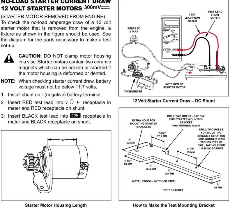
NO‑LOAD STARTER CURRENT DRAW
12 VOLT STARTER MOTORS
300mV
(STARTER MOTOR REMOVED fROM ENGINE) To check the no‑load amperage draw of a 12 volt starter motor that is removed from the engine, a fixture as shown in the figure should be used. See the diagram for the parts necessary to make a test set‑up.
CAUTION: DO NOT clamp motor housing
in a vise. Starter motors contain two ceramic magnets which can be broken or cracked if the motor housing is deformed or dented.
NOTE: When checking starter current draw, battery
voltage must not be below 11.7 volts.
1. Install shunt on - (negative) battery terminal.
2. Insert RED test lead into v receptacle in
meter and RED receptacle on shunt.
3. Insert BLACK test lead into COM receptacle in
meter and BLACK receptacle on shunt.
How to Make the Test Mounting Bracket Starter Motor Housing Length
TABLE 1
12 VOLT STARTER MOTOR SPECIFICATIONS
MOTOR HOUSING LENGTH MINIMUM RPM MAXIMUM AMPERAGE
3" (76 mm) 6500 18
3‑5/8" (92 mm) 6500 18
3‑3/4" (95 mm) 6500 19
4‑3/8" (111 mm) 6500 20
4‑1/2" (114 mm) 6500 35
4. Rotate meter selector to 300mV position.
5. Activate the starter switch:
a. Note RPM on vibration tachometer. b. Note amperage on meter.
6. Note starter motor housing length and refer to
Table 1 for test specifications for starter motor being tested.
7. If the starter motor does not meet the specifications shown in the chart, refer to the Repair Instruction Manual, Section 7, for service and repair procedure.
PRESS TO START “L” TACHOMETER NOTE RPM OF STARTER MOTOR TEST LEAD FROM METER TEST LEAD FROM METER
EXTRA HOLE FOR MOUNTING STARTER
BRACKETS
DRILL TWO HOLES – 3/8" DIA. FOR STARTER MOUNTING
BRACKET PART NUMBER 392749
DRILL TWO HOLES FOR MOUNTING BRIGGS & STRATTON PART NUMBER 19200 TACHOMETER #7 DRILL TAP HOLE FOR
1/4-20 NC SCREWS
TEST BRACKET METAL STOCK – 1/4" THICK STEEL
2" 51 MM 3-1/2" 89 MM 2-1/4" 57.2 MM 4" 102 MM 3-1/2" 89 MM 1 " 25.4 MM 10" 254 MM
STARTER CURRENT DRAW –
12 VOLT STARTER MOTORS
300mV
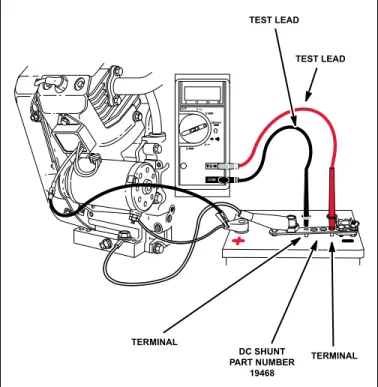
(STARTER MOTOR MOUNTED ON ENGINE) To check the amperage draw of a starter motor mounted on the engine, the procedure is similar to checking the starter motor off the engine. The battery cable and key switch harness installed in the equipment may be substituted for the test harness shown.
When making this current draw test, it is important to monitor the engine RPM, amperage draw and battery voltage. On all 12 volt starter systems, make sure the test is performed with the correct oil in engine, and belts removed from the PTO shaft. Remove the spark plug(s) and ground the spark plug wire(s) using Ignition Tester(s), Tool part
number 19368. Also the engine temperature should
be at least 68 to 70° f (20° C).
NOTE: When checking starter current draw, battery
voltage must not be below 11.7 volts.
1. Install shunt on - (negative) battery terminal.
2. Insert RED test lead into v receptacle in
meter and RED receptacle on shunt.
3. Insert BLACK test lead into COM receptacle in
meter and BLACK receptacle on shunt. 4. Rotate meter selector to position. 5. Activate the starter switch:
a. Note RPM on vibration tachometer. b. Note amperage on meter.
6. If the amperage draw exceeds 100 amps and the engine RPM is less than 350, it could indicate a starter motor problem. Check the starting system, such as the battery, cables, solenoid and connections. Then proceed to check the starter motor by performing the no‑load starter motor test as indicated on page 8 or refer to the Briggs & Stratton Repair Instruction Manual, Section 7.
12 Volt Starter Current Draw – DC Shunt
TEST LEADS FROM METER IGNITION TESTER TOOL PART NUMBER 19368 NEGATIVE BATTERY TERMINAL
AC VOLTAGE OUTPUT CHECK v
1. Insert RED test lead into v receptacle in
meter.
2. Insert BLACK test lead into COM receptacle in
meter.
3. Rotate selector to position.
4. Attach RED test clip to alternator AC output terminal(s).
5. Attach BLACK test clip to engine ground.
NOTE: When checking AC voltage output of stator
on 10‑16 and 20 amp regulated or Quad‑ Circuit alternator systems, attach one meter test clip to each output pin terminal in YELLOW connector from stator. Test clip leads may be attached to either output pin. 6. With engine running at 3600 RPM, AC output
reading should be close to specification listed for alternator type in Table 2.
AC Voltage Output Check TABLE 2
ALTERNATOR AC OUTPUT AT 3600 RPM
AC ONLY 14 VOLTS
DUAL CIRCUIT 14 VOLTS
• 5 AMP REGULATED 28 VOLTS
• 9 AMP REGULATED 40 VOLTS
TRI‑CIRCUIT 28 VOLTS
QUAD‑CIRCUIT 30 VOLTS
• 10 AMP REGULATED 20 VOLTS
• 16 AMP REGULATED 30 VOLTS
• 16 AMP REGULATED 26 VOLTS
• 20 AMP REGULATED 29 VOLTS
• 20-50 AMP REGULATED from each winding5 VOLTS ‑
• Alternator output is determined by, flywheel, alternator and magnet size.
WHITE CONNECTOR DUAL CIRCUIT RED CLIP TO AC SIDE OF HARNESS (BLACK WIRE) TEST CLIP TO AC OUTPUT PIN TEST CLIP TO A GOOD GROUND SURFACE WHITE CONNECTOR TEST CLIP GREEN CONNECTOR YELLOW CONNECTOR TEST CLIP ATTACH METER TEST CLIPS QUAD-CIRCUIT 10 AMP CIRCUIT
16 AMP CIRCUIT 9 AMP REGULATED TRI-CIRCUIT
SINGLE CIRCUIT AC ONLY
DC AMPERAGE OUTPUT CHECK
See Note Below For 1/2 Amp and System 3 & 4 Alternators
See Page 12 for Special Instructions on Checking DC Amperage Output of 16 and 20 Amp Regulated System
1. Insert RED test lead into receptacle in
meter.
2. Insert BLACK test lead into COM receptacle in
meter.
3. Rotate selector to position.
4. Attach RED test clip to DC output terminal.
5. Attach BLACK test clip to + (positive) battery
terminal. (See note for System 3 & 4 alternators.) 6. With engine running at 3600 RPM, DC output
reading should be close to specifications listed for alternator type shown in Table 3.
NOTE: 1/2 AMP AND SYSTEM 3 & 4
DC AMPERAGE OUTPUT CHECK:
follow DC output check procedure as described above through step 4.
At step 5, attach BLACK test clip to ground.
At step 6, with engine running at 2800 RPM, DC output should be no less than 0.5 amp.
DC Amperage Output Check
* Connect test leads before starting engine. Be sure connections are secure. If a test lead vibrates loose while engine is running, the regulator/ rectifier may be damaged.
** Amperage will vary with battery voltage. If battery voltage is at its maximum, the amperage will be less than the higher value shown.
TABLE 3
ALTERNATOR TYPE DC OUTPUT
1/2 AMP, SYSTEM 3 & 4 .5 AMP
DC ONLY (VANGUARD™) (1.2 AMP) 1.2 AMP
DC ONLY (MODEL 130000) (1.5 AMP) 1.5 AMP
DC ONLY (3 AMPS) **2–4 AMPS
DUAL CIRCUIT **2–4 AMPS
TRI CIRCUIT 5 or 9 AMP
DUAL CIRCUIT 5 AMP DC
*QUAD‑CIRCUIT **3–8 AMPS
*5 AMPS REGULATED **3–5 AMPS
*9 AMPS REGULATED **3–9 AMPS
*10 AMPS REGULATED **3–10 AMPS
*16 AMPS REGULATED **3–16 AMPS
*20 AMPS REGULATED **3–20 AMPS
TEST LEAD TO DC OUTPUT PIN “BUMP” ON CONNECTOR
INDICATES THE DC OUTPUT PIN LOCATION
LEAD TO POSITIVE BATTERY TERMINAL AC OUTPUT PIN DC OUTPUT PIN DUAL CIRCUIT SYSTEM
CHECKING DC AMPERAGE
OUTPUT
16 & 20 AMP REGULATED
ALTERNATOR
To avoid blowing fuse in meter when testing DC output of 16 and 20 amp system the DC Shunt, Tool
part number 19468, is required.
The DC Shunt must be installed on the - (negative)
terminal of the battery. All connections must be clean and tight for correct amperage readings.
1. Install shunt on negative battery terminal.
2. Insert RED test lead into v receptacle in
meter and RED receptacle on shunt.
3. Insert BLACK test lead into COM receptacle in
meter and BLACK receptacle on shunt.
4. Rotate selector to 300mV position.
5. With engine running at 3600 RPM, DC output reading should be close to specifications listed in
Table 3. 16 and 20 Amp System – DC ShuntDC Amperage Output Check
TEST LEAD DC SHUNT PART NUMBER 19468 TEST LEAD TERMINAL TERMINAL
STARTER MOTOR CURRENT DRAW
120 VOLT STARTER MOTORS A
Use Line Current Adapter, Tool part number 19358,
when checking current draw on 120 volt starter motors. Use the same test fixture used in the 12 volt starter test to check the current draw and free running RPM of motor.
The following test procedure must be used to avoid any accidental shock hazard to the service technician.
1. Insert BLACK test lead from adapter, Tool part
number 19358, into the COM receptacle in meter.
2. Insert white test lead from adapter, Tool part
number 19358, into the receptacle in
meter.
3. Plug the adapter cord (female end) into the switch box receptacle of the starter motor.
4. Plug the adapter cord (male end) into the previously tested wall outlet.
5. Rotate selector to A position.
6. Refer to specifications, Table 4, and note maximum allowable amperage draw for motor being tested.
7. Depress starter switch button. When meter reading stabilizes, (approximately 3 seconds) amperage should not exceed the specification shown in Table 4.
CAUTION: If amperage is higher than specification in Table 4, immediately stop the test! An amperage reading higher than number in chart, indicates a shorted starter motor, which could be dangerous.
120 Volt AC Starter Motor Current Draw with Line Current Adapter
8. If starter motor amperage is within specification, check RPM using vibration tachometer, Tool part
number 19200.
9. RPM should be close to specifications listed in Table 4.
10. If the starter motor does not meet the given specifications, refer to the Repair Instructions Manual, Section 7.
TABLE 4
120 VOLT STARTER MOTOR SPECIFICATIONS STARTER MOTOR
IDENTIFICATION AMPERAGEMAXIMUM MINIMUM RPM
American Bosch SME–110–C3 SME–110–C6 SME–110–C8 3.5 7400 American Bosch 06026–28–M030SM 3.0 7400 Mitsubishi J282188 3.5 7800
Briggs & Stratton
3‑1/2˝ (75.45 mm) Motor Housing 2.7 6500 PUSH SWITCH TO ACTIVATE STARTER TACHOMETER READ RPM OF STARTER MOTOR
AC LINE VOLTAGE MUST BE NO LESS THAN 110 VOLTS
ELECTRIC STARTER KITS QUICK REFERENCE
ENGINE MODEL STARTER ASSEMBLY# STARTER GEAR ONLY# DRIVE ASSY. # (BENDIX)
Snow Engines ‑ 120 Volt Starter Kit
12B400 754185 (Kit) 390922 (Starter Motor Only)
12C300 754185 (Kit) 12C400 754185 (Kit) 12D300 754185 (Kit) 12D400 754185 (Kit)
Snow Engines ‑ 230 Volt Starter Kit (Europe Only)
Models 12 & 15
Series 800 & Series 1100 699786 (Kit) 390922 (Starter Motor Only) Models 20 & 21
Series 1300 & Series 1500 792157 (Kit)
Single Cylinder Engines
190400‑196499 693054 (Plastic Ring Gear) 695708 (Plastic Ring Gear) 696541 (C Ring Type) 190700‑195799 693054 (Alum. Ring Gear) 695708 (Alum. Ring Gear) 696540 (Roll Pin Type) 252700‑252799 693551 (Steel Ring Gear) 693713 (Steel Ring Gear) 693699 (Steel Ring Gear) 253700‑253799 795121 (Plastic Ring Gear/Starter
Housing is Over 4" in Length) 194700‑198799 795121 (Alum. Ring Gear/Starter Housing
is Over 4" in Length)
195400‑195799 693552 (Steel Ring Gear/Starter Housing is Over 4" in Length) 19E400‑19E499 19f400‑19f499 19G400‑19G499 19K400‑19K499 280700‑289799 28A700‑28W799
Single Cylinder Intek™ Engines
120100‑15D100 793667 120 volt (60Hz Starter Assembly) 699786 230 volt (50Hz Starter Assembly) 20A100‑21P200 795909 120 volt (60HZ Starter Assembly) 792157 230 volt (50Hz Starter Assembly)
310700‑310799 497595 (Plastic Ring Gear) 695708 (Plastic Ring Gear) 696541 (C Ring Type) 311700‑311799 497595 (Alum. Ring Gear) 695708 (Alum. Ring Gear)
312700‑312799 693551 (Steel Ring Gear) 693699 (Steel Ring Gear) 693713 (Steel Ring Gear)
Opposed Twin Cylinder Engines
400400‑422499 497596 (3 5/8" Housing) 695708 696541 (C Ring Type)
400700‑422799 498148 (4 3/8" Housing) 696540 (Roll Pin Type)
42A700‑42E799 496181 (Steel Pinion Gear)
406700‑461799
V-Twin Vanguard™ Engines
303400‑303499 499521 695708 696541 (C Ring Type)
354400‑354499 691564 (Steel Pinion Gear) N/A (Steel Pinion Gear) 496881 (Steel Pinion Gear) 350700‑350799
380400‑381499 380700‑381799
303700‑303799 499521 695708 696541 (C Ring Type)
304400‑304499 691564 (Steel Pinion Gear) N/A (Steel Pinion Gear) 496881 (Steel Pinion Gear) 350400‑350499
351400‑351499 351700‑351799
381400‑381499 691564 (Steel Pinion Gear) 695708 696541 (C Ring Type)
381700‑381799
V-Twin Intek™ Engines
405700‑405799 499521 695708 696541
406700‑406799 407700‑407799 445700‑445799
Briggs & Stratton engines are equipped with a number of different alternator systems to meet the requirements of equipment manufacturers. for example, a large lawn tractor with accessories may require a 16 amp regulated system, whereas a snow thrower with a single headlight requires an AC Only system. Knowing the type of alternator system an
engine is equipped with is important, particularly when an engine is being replaced.
Briggs & Stratton alternator systems are easily identified by the color of the stator output wire(s) and the connector. DC Only AC Only STATOR OUTPUT WIRE(S) AND CONNECTOR (TYPICAL)
ALTERNATOR IDENTIFICATION
• 14 Volts AC for lighting circuit. • One BLACK lead from stator. • White connector output lead.
• 3 amp DC unregulated for charging battery. • One RED lead from stator.
• Diode encased at connector. • RED connector output lead. ONE LEAD FROM
ENGINE (STATOR)
TO EQUIPMENT
HARNESS CONNECTOR
OUTPUT LEAD
ONE LEAD FROM ENGINE (STATOR)
TO EQUIPMENT HARNESS
CONNECTOR
DIODE
C-Ring Type Roll Pin Type Steel Ring Gear
CLUTCH DRIVE RETAINER RETURN SPRING PINION GEAR BEVELED EDGE UP STARTER CLUTCH WASHER ROLL PIN-SLOT UP STARTER DRIVE ASSEMBLY HELIX PINION GEAR DUST COVER RETAINING RING UPPER RETAINER SPRING CLUTCH LOWER RETAINER STARTER MOTOR RETAINING RING FLAT WASHER WAVE WASHER
• 3 amp DC unregulated for charging battery (ONE RED lead from stator).
• 14 Volts AC for lighting circuit (ONE BLACK lead from stator). • Diode encased at connector.
• White connector with two pin terminals. LEADS FROM ENGINE
(STATOR) TO EQUIPMENT HARNESS Tri-Circuit Dual Circuit LEAD DC OUTPUT LEAD AC OUTPUT LEAD AC FOR LIGHTS CONNECTOR DC CHARGING CIRCUIT RED LEAD • 10 amp AC.
• One BLACK lead from stator. • GREEN connector.
• Two diodes encased in wire harness. • RED and white output leads.
• 5 or 9 amp DC regulated for charging battery. • Alternator output (5 or 9 amp) is determined by flywheel alternator magnet size.
• Uses same stator as Tri-Circuit system. • One BLACK lead from stator.
• GREEN connector. 5 or 9 Amp Regulated TO EQUIPMENT HARNESS 5 AMP DC (-) TO LIGHTS WHITE LEAD
TWO DIODES ENCASED IN WIRE HARNESS
ONE BLACK LEAD FROM ENGINE
(STATOR)
CONNECTOR LEAD 5 AMPS DC (+)
TO BATTERY AND CLUTCH CIRCUIT
CONNECTOR TO EQUIPMENT HARNESS LEAD FROM ENGINE (STATOR) CONNECTOR YELLOW WIRE REGULATOR/ RECTIFIER
• 10 or 16 amp DC regulated for charging battery. • Alternator output is determined by the flywheel alternator magnet size.
• 10 and 16 amp system use the same stator, color coding and regulator/rectifier.
• Two BLACK leads from stator.
• YELLOW connector with two pin terminals. • Two YELLOW leads to regulator/rectifier. • One RED lead from regulator/rectifier to RED connector output lead.
10 OR 16 Amp Regulated REGULATOR/ RECTIFIER TO EQUIPMENT HARNESS CONNECTOR TWO YELLOW LEADS
ONE RED
LEAD TWO BLACK LEADS FROM ENGINE
(STATOR) CONNECTOR
OUTPUT LEAD
• Uses same stator as 10 and 16 amp system. • DC output the same as 10 or 16 amp system. • Charge indicator light and wiring supplied by equipment manufacturer.
• RED DC output wire to white connector.
• BLUE charge indicator wire to white connector.
493219 Regulator/Rectifier Used With Charge Indicator Circuit
TO EQUIPMENT HARNESS
TWO YELLOW
LEADS CONNECTOR
CONNECTOR
RED WIRE AND RAISED RIB INDICATES DC OUTPUT
ENGINE/ALTERNATOR REPLACEMENT INFORMATION
With the exception of the AC Only alternator, all of the alternator systems referred to in this book have a battery as part of the electrical system.
There are specialized applications that use an alternator without a battery. An example would be certain generators or welders that use alternator output to excite an electrical field. for the equipment to function, the alternator output must be very evenly matched to the equipment requirements. When replacing an engine in these applications, the alternator must be the same as the original.
REPLACING BRIGGS & STRATTON® ENGINES
When replacing an older Briggs & Stratton engine on a piece of equipment with a newer Briggs & Stratton engine, sometimes the newer engine has an alternator system different from the alternator system on the original engine. This means that the output connector on the replacement engine is not compatible with the original wiring harness on the piece of equipment. for example, the original engine may have been equipped with a Dual Circuit system and the replacement engine is equipped with a regulated system. We can integrate the two systems by making an adapter harness from readily available parts.
Generally an unregulated DC system (DC Only, Dual Circuit) should not be used to replace a regulated system because alternator output may not be sufficient for equipment requirements. However, because the equipment requirements are usually much less on an unregulated DC system, a regulated system may be used as a replacement. The regulator/rectifier prevents the battery from being over charged.
NOTE: The AC Only, DC Only, Dual Circuit, Tri‑Circuit as well as the 5 and 10 amp regulated systems use
flywheels with small alternator magnets. The 9 and 16 amp regulated systems use flywheels with the large alternator magnets. See figure below for magnet sizes.
ALTERNATOR MAGNETS *Small Magnet 7/8" x 11/16" (22mm x 18mm) *Large Magnet 1‑1/16" x 15/16" (27mm x 24mm)
*V Twin Alternator Magnet Size: Small 7/8" x 21/32" (22 mm x 17 mm) Large 7/8" x 29/32" (22 mm x 23 mm)
The following are alternator replacement combinations which require an adapter harness. All of the necessary components are shown.
2. Original engine equipped with DC Only alternator. Replacement engine equipped with Dual Circuit alternator.
Modify 398661 harness supplied with replacement engine by removing white AC wire. Then, splice 393537
connector into RED DC wire and connect to equipment harness. See Fig. 2
EQUIPMENT HARNESS - FEMALE WHITE CONNECTOR 393456 - DUAL CIRCUIT
REPLACEMENT CONNECTOR HARNESS
BLACK WIRE DC RED WIRE
398661 HARNESS - FEMALE DUAL CIRCUIT CONNECTOR - MALE
(FROM ENGINE)
AC
DC
RIB
RIB SPLICE CONNECTOR - MALE393537 - GREEN DIODE EQUIPMENT HARNESS - FEMALE WHITE CONNECTOR AC WHITE WIRE 398661 HARNESS - FEMALE DUAL CIRCUIT CONNECTOR - MALE
(FROM ENGINE) 393456 - DUAL CIRCUIT REPLACEMENT CONNECTOR HARNESS
AC
DC
RIB RIB
SPLICE
393537 - GREEN
CONNECTOR - MALE BLACK WIRE
DIODE
Fig. 1
Fig. 2
1. Original engine equipped with AC Only alternator. Replacement engine equipped with Dual Circuit alternator.
Modify 398661 harness supplied with replacement engine by removing RED DC wire. Then, splice 393537
4. Original engine equipped with Tri‑Circuit alternator. Replacement engine equipped with 5, 9, 10 or 16 amp regulated system.
Modify 692306 harness supplied with replacement engine by splicing into charging circuit wire and lighting
circuit wire in equipment harness. See Fig. 4
NOTE: THE DIODES MUST BE REMOVED fROM THE 692306 HARNESS BEING CONNECTED TO THE
EQUIPMENT HARNESS. RED WIRE RED CONNECTOR EQUIPMENT HARNESS 692306 HARNESS - FEMALE SPLICE OUTPUT CONNECTOR
FROM REGULATOR - MALE
LIGHTING CIRCUIT WIRE
CHARGING CIRCUIT WIRE
Fig. 4
3. Original engine equipped with Dual Circuit alternator. Replacement engine equipped with 5, 9, 10 or 16 amp regulated system.
Modify 692306 harness supplied with replacement engine by splicing in 399916 connector assembly. Connect
to equipment harness. See Fig. 3
NOTE: THE DIODES MUST BE REMOVED fROM THE EQUIPMENT HARNESS.
398661 EQUIPMENT HARNESS - FEMALE RIB RIB END PROFILE MALE FEMALE 692306 HARNESS - FEMALE RED WIRE RED CONNECTOR
RED WIRE BLACK WIRE
SPLICE OUTPUT CONNECTOR
FROM REGULATOR - MALE
399916 CONNECTOR ASSEMBLY - MALE
Fig. 5
5. Original engine equipped with Dual Circuit alternator. Replacement engine equipped Tri‑Circuit alternator.
Discard 691955 diode harness supplied with new engine. Install 794360 regulator/rectifier. Add 692306
harness and modify by splicing in 399916 connector assembly. Connect to equipment harness. See Fig. 5
398661 - EQUIPMENT HARNESS - FEMALE
RIB RIB
692306
HARNESS - FEMALE BLACKWIRE
SPLICE 393537 - OUTPUT CONNECTOR
FROM REPLACEMENT ALTERNATOR - MALE
399916 CONNECTOR ASSEMBLY - MALE
794360 REGULATOR/RECTIFIER
6. Original engine equipped with 5 amp regulated system. Replacement engine equipped with Tri‑Circuit alternator.
Discard 691955 diode harness supplied with new engine. Transfer 491546 regulator/rectifier from original
engine to the new engine. Connect to equipment harness.
The following alternator replacement combinations require no modifications.
7. Original engine equipped with DC Only alternator. Replacement engine equipped with 5, 9, 10 or 16 amp regulated system. Direct Replacement. Connect to equipment harness.
8. Original engine equipped with 5 amp regulated system. Replacement engine equipped with 9, 10 or 16 amp regulated system. Direct Replacement. Connect to equipment harness.
9. Original engine equipped with 9 amp regulated system. Replacement engine equipped with 10 or 16 amp regulated system. Direct Replacement. Connect to equipment harness.
10. Original engine equipped with 10 amp regulated system. Replacement engine equipped with 9 or 16 amp regulated system. Direct Replacement. Connect to equipment harness.
BRIGGS & STRATTON® ENGINE/REPLACING ENGINE OF
ANOTHER MANUFACTURER
When replacing the engine of another manufacturer with a Briggs & Stratton engine, the equipment requirements must be known so that the replacement alternator system has the same output as the original system provided.
Often the equipment wiring harness is not compatible with the Briggs & Stratton alternator output harness. To create a compatible system it may be necessary to modify the equipment wiring harness. To do this, a wiring diagram for the equipment is essential.
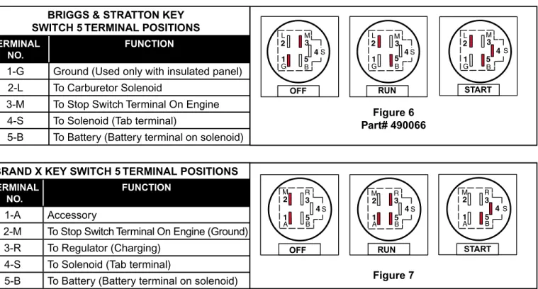
appear to be identical, there are internal differences to keyswitches. Therefore it is necessary to have a diagram of the keyswitch showing the terminal positions and their functions. for example, see the 5 terminal switch diagrams in figure 1 and figure 2. The keyswitch in figure 1 is compatible with all Briggs & Stratton alternators. Note in figure 2, that when the “brand X” keyswitch is in the START position there is no battery voltage available to the #2 switch terminal. Consequently, if the replacement Briggs & Stratton engine was equipped with a carburetor solenoid, it would not function. This is why it is important to have a diagram of the keyswitch when replacing engines, or replace the keyswitch with one that is compatible with all Briggs & Stratton alternator systems.
It is not possible to show all of the wiring diagrams or keyswitch combinations that are used by equipment manufacturers. However, the following wiring diagrams for the most popular Briggs & Stratton engines may be used as a guide when replacing an engine. The wiring diagrams show the type of keyswitch that is compatible with the alternator system shown.
6 5 4 3 2 1 L M G A A 1-6-3 2-5-6 2-4-5 S 6 5 4 3 2 1 L M G A A S 6 5 4 3 2 1 L M G A A S
OFF RUN START
Figure 8 Part# 692318 TERMINAL
NO. FUNCTION
1 Ground (Used only with insulated panel)
2 To Carburetor Solenoid
3 To Stop Switch Terminal On Engine
4 To Solenoid (Tab terminal)
5 To Battery (Battery terminal on solenoid)
6 To Alternator (DC Output)
NOTE: The 5 terminal Briggs & Stratton keyswitch, part number 490066, shown in figure 1 has been
replaced by a 6 terminal keyswitch, part number 692318. The additional terminal provides a direct
connection for the charging lead at the keyswitch. This is a "Truth Table"
5 3 2 1 M G L S B 5 3 2 1 M G L S B 5 3 2 1 M G L S B 4 4 4
BRIGGS & STRATTON KEY SWITCH 5 TERMINAL POSITIONS
TERMINAL
NO. FUNCTION
1‑G Ground (Used only with insulated panel)
2‑L To Carburetor Solenoid
3‑M To Stop Switch Terminal On Engine
4‑S To Solenoid (Tab terminal)
5‑B To Battery (Battery terminal on solenoid)
OFF RUN START
Figure 6 Part# 490066
OFF RUN START
BRAND X KEY SWITCH 5 TERMINAL POSITIONS
TERMINAL
NO. FUNCTION
1‑A Accessory
2‑M To Stop Switch Terminal On Engine (Ground)
3‑R To Regulator (Charging)
4‑S To Solenoid (Tab terminal)
5‑B To Battery (Battery terminal on solenoid) Figure 7
5 3 2 1 M A R S B 5 3 2 1 M A R S B 5 3 2 1 M A R S B 4 4 4
5 4 3 2 1
+
-+ −
Typical Dual Circuit Alternator Wiring Diagram
Original 5-Pole Key Switch Part# 490066 Superceded to 6-Pole Key Switch, Briggs & Stratton Part# 692318 KEY SWITCH TEST
SWITCH POSITION CONTINUITY
1. Off *1 + 3
2. RUN 2 + 5
3. START 2 + 4 + 5
*Terminal 1 Grounded Internally To Key Switch Case
TERMINAL NO. FUNCTION
1 Ground (Used only with insulated panel)
2 To Carburetor Solenoid
3 To Stop Switch Terminal On Engine
4 To Solenoid (Tab terminal)
5 To Battery (Battery terminal on solenoid)
ALTERNATOR KEY SWITCH ANTI-AFTERFIRE SOLENOID STOP SWITCH TERMINAL SOLENOID TAB TERMINAL TO STARTER TERMINAL SOLENOID TO BATTERY TERMINAL STARTER MOTOR 12 VOLT BATTERY HEADLIGHTS AMMETER HEADLIGHT SWITCH AC OUTPUT WIRE DC OUTPUT WIRE RED DIODE RED RED RED RED RED
5 4 3 2 1
+
-6 + − + −
Typical Dual Circuit Alternator Wiring Diagram
6-Pole Key Switch − Briggs & Stratton Part# 692318
KEY SWITCH TEST
SWITCH POSITION CONTINUITY
1. Off *1 + 3 + 6
2. RUN 2 + 5 + 6
3. START 2 + 4 + 5
*Terminal 1 Grounded Internally To Key Switch Case
TERMINAL NO. FUNCTION
1 Ground (Used only with insulated panel)
2 To Carburetor Solenoid
3 To Stop Switch Terminal On Engine
4 To Solenoid (Tab terminal)
5 To Battery (Battery terminal on solenoid)
6 To Alternator (DC Output) ALTERNATOR KEY SWITCH ANTI-AFTERFIRE SOLENOID STOP SWITCH TERMINAL SOLENOID TAB TERMINAL TO STARTER TERMINAL SOLENOID TO BATTERY TERMINAL STARTER MOTOR 12 VOLT BATTERY HEADLIGHTS AMMETER HEADLIGHT SWITCH AC OUTPUT WIRE DC OUTPUT WIRE DIODE AMMETER (OPTIONAL)
With ammeter shown in optional position, note that − and + symbols are reversed. The + symbol must always be
connected to the alternator side.
RED
RED
RED
RED
6 4 3 5 2 1
Typical Dual Cir
cuit System S TAT O R ST AR TER SOLENOID B A TTER Y ST AR TER BLA CK AC OUTPUT WHITE CONNECT OR DIODE RED DC OUTPUT AMMETER ST AR T SWITCH LIGHT SWITCH RED RED RED RED RED RED
5 4 3 2 1
+
-+ −
Typical 16 Amp Regulated Alternator Wiring Diagram
5-Pole Key Switch − Briggs & Stratton Part# 692318
KEY SWITCH TEST
SWITCH POSITION CONTINUITY
1. Off *1 + 3
2. RUN 2 + 5
3. START 2 + 4 + 5
*Terminal 1 Grounded Internally To Key Switch Case
TERMINAL NO. FUNCTION
1 Ground (Used only with insulated panel)
2 To Carburetor Solenoid
3 To Stop Switch Terminal On Engine
4 To Solenoid (Tab terminal)
5 To Battery (Battery terminal on solenoid)
ALTERNATOR KEY SWITCH ANTI-AFTERFIRE SOLENOID STOP SWITCH TERMINAL SOLENOID TAB TERMINAL TO STARTER TERMINAL SOLENOID TO BATTERY TERMINAL STARTER MOTOR 12 VOLT BATTERY HEADLIGHTS AMMETER HEADLIGHT SWITCH AC OUTPUT WIRE DC OUTPUT RED WIRE REGULATOR/ RECTIFIER YELLOW RED RED RED RED
-6 5 4 3 2 1 + −
+
+ −Typical 16 Amp Regulated Alternator Wiring Diagram
6-Pole Switch − Briggs & Stratton Part# 692318
KEY SWITCH TEST
SWITCH POSITION CONTINUITY
1. Off *1 + 3 + 6
2. RUN 2 + 5 + 6
3. START 2 + 4 + 5
*Terminal 1 Grounded Internally To Key Switch Case
TERMINAL NO. FUNCTION
1 Ground (Used only with insulated panel)
2 To Carburetor Solenoid
3 To Stop Switch Terminal On Engine
4 To Solenoid (Tab terminal)
5 To Battery (Battery terminal on solenoid)
6 To Alternator (DC Output) ALTERNATOR KEY SWITCH ANTI-AFTERFIRE SOLENOID STOP SWITCH TERMINAL SOLENOID TAB TERMINAL TO STARTER TERMINAL SOLENOID TO BATTERY TERMINAL STARTER MOTOR 12 VOLT BATTERY HEADLIGHTS AMMETER HEADLIGHT SWITCH AC OUTPUT WIRE DC OUTPUT RED WIRE REGULATOR/ RECTIFIER AMMETER (OPTIONAL)
With ammeter shown in optional position, note that − and + symbols are reversed. The + symbol must always be
connected to the alternator side. YELLOW
RED
RED RED
-6 5 4 3 2 1 + −
+
+ −Typical 16 Amp Regulated Alternator Wiring Diagram With Charge Indicator Light
6-Pole Switch − Briggs & Stratton Part# 692318
KEY SWITCH TEST
SWITCH POSITION CONTINUITY
1. Off *1 + 3 + 6
2. RUN 2 + 5 + 6
3. START 2 + 4 + 5
*Terminal 1 Grounded Internally To Key Switch Case
TERMINAL NO. FUNCTION
1 Ground (Used only with insulated panel)
2 To Carburetor Solenoid
3 To Stop Switch Terminal On Engine
4 To Solenoid (Tab terminal)
5 To Battery (Battery terminal on solenoid)
6 To Alternator (DC Output) ALTERNATOR BLUE WIRE ANTI-AFTERFIRE SOLENOID STOP SWITCH TERMINAL SOLENOID TAB TERMINAL TO STARTER TERMINAL SOLENOID TO BATTERY TERMINAL STARTER MOTOR 12 VOLT BATTERY HEADLIGHTS AMMETER HEADLIGHT SWITCH AC OUTPUT WIRE CHARGE INDICATOR LIGHT REGULATOR/ RECTIFIER AMMETER (OPTIONAL) RED WIRE DC OUTPUT RAISED RIB
With ammeter shown in optional position, note that − and + symbols are reversed. The + symbol must always be
connected to the alternator side. YELLOW
RED RED
6 4 3 5 2 1
-+
Typical 10/16 Amp System
ST AR TER RELA Y SEA T SWITCH GR OUND WIRE TERMINAL AL TERNA TOR ST AR TER AMMETER
CLUTCH BRAKE SWITCH D B C A C B A B A C D E LIGHT SWITCH ELECTRIC CLUTCH B A TTER Y RED RED RED RED RED
+
-6 5 4 3 2 1 + − + −
Typical 5/9 Amp Regulated Alternator Wiring Diagram With Charge Indicator Light
6-Pole Switch − Briggs & Stratton Part# 692318
KEY SWITCH TEST
SWITCH POSITION CONTINUITY
1. Off *1 + 3 + 6
2. RUN 2 + 5 + 6
3. START 2 + 4 + 5
*Terminal 1 Grounded Internally To Key Switch Case
TERMINAL NO. FUNCTION
1 Ground (Used only with insulated panel)
2 To Carburetor Solenoid
3 To Stop Switch Terminal On Engine
4 To Solenoid (Tab terminal)
5 To Battery (Battery terminal on solenoid)
6 To Alternator (DC Output) ALTERNATOR KEY SWITCH ANTI-AFTERFIRE SOLENOID STOP SWITCH TERMINAL SOLENOID TAB TERMINAL TO STARTER TERMINAL SOLENOID TO BATTERY TERMINAL STARTER MOTOR 12 VOLT BATTERY HEADLIGHTS AMMETER HEADLIGHT SWITCH AC OUTPUT WIRE TRI-CIRCUIT STATOR REGULATOR/ RECTIFIER AMMETER (OPTIONAL) DC OUTPUT RED WIRE
With ammeter shown in optional position, note that − and + symbols are reversed. The + symbol must always be
connected to the alternator side.
GREEN
RED
RED RED
6 5 4 3 2 1 + −
+
-+ −
Typical Tri-Circuit Alternator Wiring Diagram
6-Pole Switch − Briggs & Stratton Part# 692318
KEY SWITCH TEST
SWITCH POSITION CONTINUITY
1. Off *1 + 3 + 6
2. RUN 2 + 5 + 6
3. START 2 + 4 + 5
*Terminal 1 Grounded Internally To Key Switch Case
TERMINAL NO. FUNCTION
1 Ground (Used only with insulated panel)
2 To Carburetor Solenoid
3 To Stop Switch Terminal On Engine
4 To Solenoid (Tab terminal)
5 To Battery (Battery terminal on solenoid)
6 To Alternator (DC Output) ALTERNATOR KEY SWITCH ANTI-AFTERFIRE SOLENOID STOP SWITCH TERMINAL SOLENOID TAB TERMINAL TO STARTER TERMINAL SOLENOID TO BATTERY TERMINAL STARTER MOTOR 12 VOLT BATTERY HEADLIGHTS AMMETER ELECTRIC CLUTCH AC OUTPUT WIRE TRI-CIRCUIT STATOR HEADLIGHT SWITCH AMMETER (OPTIONAL) + DC OUTPUT WIRE - DC OUTPUT WIRE CLUTCH SWITCH
With ammeter shown in optional position, note that − and + symbols are reversed. The + symbol must always be
connected to the alternator side.
GREEN
RED
RED
RED RED
Simplified “T ri-Cir cuit” System 4 3 5 2 1 B A C D E LIGHT SWITCH B A TTER Y S TAT O R ST AR TER ST AR TER SOLENOID ST AR T SWITCH INTERLOCK SWITCH P T O SWITCH 1 25W RESIST OR GREEN CONNECT OR CLUTCH RED RED RED RED WHITE WIRE
5 4 3 2
+
1−
+ − A B ON OFF Note: If clutch switch is in ON position with k
eys
witch O
ff
,
batter
y will discharge through clutch.
To pre
vent this
, route wire B to #2 ter
minal on k ey ‑s witch. Ho w ev er , anti
‑afterfire solenoid will not shut off
. Remo
ve
anti
‑afterfire solenoid or con
ver t system to 6 pole s witch. K EY S WITCH T EST S WITCH P OSITION C ONTINUITY 1. O ff *1 + 3 2. R UN 2 + 5 3. ST AR T 2 + 4 + 5 *T er
minal 1 Grounded Inter
nally
To K
ey Switch Case Typical
Tri-Cir cuit Alternator Wiring Dia gram – With Resistor – 5-P ole Switc h − Brig gs & Stratton P ar t# 692318 AL TERNA TOR KEY SWITCH ANTI-AFTERFIRE SOLENOID ST OP SWITCH TERMINAL SOLENOID T AB TERMINAL ST AR TER TERMINAL SOLENOID TO B A TTER Y TERMINAL SEE NO TE 12 V OL T B A TTER Y HEADLIGHTS AMMETER ELECTRIC CLUTCH A C OUTPUT WIRE TRI-CIRCUIT S TAT O R HEADLIGHT SWITCH + DC OUTPUT RED WIRE - DC OUTPUT WIRE CLUTCH SWITCH RESIST OR ST AR TER MO TOR GREEN RED RED RED
5 4 3 2 1 + − 6 ON OFF
+
−
Typical Tri-Cir cuit Alternator Wiring Dia gram – With Resistor – 6-P ole Switc h − Brig gs & Stratton P ar t# 692318 K EY S WITCH T EST S WITCH P OSITION C ONTINUITY 1. O ff *1 + 3 2. R UN 2 + 5 3. ST AR T 2 + 4 + 5 *T erminal 1 Grounded Inter
nally To K ey Switch Case AL TERNA TOR KEY SWITCH ANTI-AFTERFIRE SOLENOID SOLENOID T AB TERMINAL TO ST AR TER TERMINAL SOLENOID TO B A TTER Y TERMINAL 12 V OL T B A TTER Y HEADLIGHTS AMMETER ELECTRIC CLUTCH A C OUTPUT WIRE TRI-CIRCUIT S TAT O R HEADLIGHT SWITCH + DC OUTPUT WIRE - DC OUTPUT WIRE CLUTCH DPDT SWITCH RESIST OR ST AR TER M OTO R ST OP SWITCH TERMINAL GREEN RED RED RED RED
Typical Comple x Tri-Cir cuit System 4 3 5 2 1
-+
B A C D E ST AR T SWITCH B A TTER Y S TAT O R ST AR TER ST AR TER RELA Y LIGHT SWITCHCLUTCH/ BRAKE SWITCH
P T O SWITCH GREEN CONNECT OR P T O CLUTCH AMMETER FUSE C D A B B A B A SEA T SWITCH RED WHITE WIRE RED RED RED RED RED
V-TWIN WIRE HARNESS
DESCRIPTION M40/44 WITH #2 SIDE
REGULATOR, W/O EFM M49 WITH #1 SIDE REGULATOR, W/O EFM M40/44/49 WITH #1 SIDE REGULATOR, WITH EFM 2 pin, standard 691220 691220 na
Used with (RED, regulator out) (Jumper Wire) 691208 797463 797463
6 pin, standard na 797424 796860
6 pin with oil pressure switch 698330 797460 797492
6 pin with hour meter or oil minder 696576 797461 796960
ASSOCIATED PARTS
Shield/Nut Assembly #1 side 796852 796852 796852
Bracket, Hold Down (wire) na 797454 797454
Tie wrap for regulator wires
(inside blower) na yes yes
VIEW FROM TERMINAL END TERMINAL END WIRE END ENGINE CONNECTION DEUTSCH 1PD-USA DT06-6S DEUTSCH 1PD-USA DT04-6P
* TO KILL ENGINE CONNECT TO GROUND
EQUIPMENT CONNECTION
6-Pin Deutsch Connections
OIL PRESSURE (GREEN)
* IGNITION (BLACK)
GROUND (BROWN)
VOLTAGE REGULATOR (RED)
STARTER SOLENOID (YELLOW)
FUEL CUT-OFF (GRAY)
VOLTAGE REGULATOR (RED WIRE) 1 2 3 4 5 6 STARTER SOLENOID ( YELLOW WIRE) FUEL SHUT-OFF (GRAY WIRE)
INSTALL SEALING PLUG IN EMPTY #6 POSITION
IGNITION KILL (BLACK WIRE)
GROUND (BROWN WIRE) OIL PRESSURE (GREEN)
IF APPLICABLE VIEW FROM TERMINAL END TERMINAL END WIRE END ENGINE CONNECTION DEUTSCH 1PD-USA DT06-6S DEUTSCH 1PD-USA DT04-6P
* TO KILL ENGINE CONNECT TO GROUND EQUIPMENT CONNECTION
6-Pin Deutsch Connections
OIL PRESSURE (GREEN)
* IGNITION (BLACK)
GROUND (BROWN)
VOLTAGE REGULATOR (RED)
STARTER SOLENOID (YELLOW)
FUEL CUT-OFF (GRAY)
VOLTAGE REGULATOR (RED WIRE) 1 2 3 4 5 6 STARTER SOLENOID ( YELLOW WIRE) FUEL SHUT-OFF (GRAY WIRE)
INSTALL SEALING PLUG IN EMPTY #6 POSITION
IGNITION KILL (BLACK WIRE)
GROUND
(BROWN WIRE)
OIL PRESSURE (GREEN) IF APPLICABLE VIEW FROM TERMINAL END TERMINAL END WIRE END ENGINE CONNECTION DEUTSCH 1PD-USA DT06-6S DEUTSCH 1PD-USA DT04-6P
* TO KILL ENGINE CONNECT TO GROUND EQUIPMENT CONNECTION
6-Pin Deutsch Connections
OIL PRESSURE (GREEN)
* IGNITION (BLACK)
GROUND (BROWN)
VOLTAGE REGULATOR (RED)
STARTER SOLENOID (YELLOW)
FUEL CUT-OFF (GRAY)
VOLTAGE REGULATOR (RED WIRE) 1 2 3 4 5 6 STARTER SOLENOID ( YELLOW WIRE) FUEL SHUT-OFF (GRAY WIRE)
INSTALL SEALING PLUG IN EMPTY #6 POSITION
IGNITION KILL (BLACK WIRE)
GROUND
(BROWN WIRE)
OIL PRESSURE (GREEN) IF APPLICABLE
Part# 790544 Adapter wire