Infrastructure for Intrusion Detection and Response
Dan Schnackenberg
Boeing Phantom Works
[email protected]
Kelly Djahandari
Dan Sterne
NAI Labs, Network Associates
[email protected]
[email protected]
Abstract
Automated response to intrusions has become a major issue in defending critical systems. Because the adversary can take actions at computer speeds, systems need the capability to react without human intervention. An infrastructure that supports development of automated response systems is critically needed. This infrastructure must allow easy integration of detection and response components to enable experimentation with automated response strategies. This paper provides an overview of the Intruder Detection and Isolation Protocol (IDIP) architecture and how it supports the need for an intrusion detection and response infrastructure.
1. Introduction
Today’s information systems in government and commercial sectors are distributed and highly interconnected via local area and wide area computer networks. While indispensable, these networks provide potential avenues of attack by hackers, international competitors, and other adversaries. To monitor and protect against such threats, organizations increasingly deploy intrusion detection systems and network boundary control devices (i.e., firewalls, filtering routers, and guards). When suspicious activities are detected, intrusion detection systems alert human administrators or automated processes that undertake corrective action, for example, reconfiguring a firewall to block incoming traffic from offending Internet addresses or terminating suspicious local processes.
Several COTS vendors have developed products that support intrusion response (e.g., [1], [2], and [3]). However these products all use proprietary protocols and are limited by an architecture that requires all response decisions to be made at a central controller. Devices such
as firewalls are simply response mechanisms and not full participants in the response decision making process.
While useful, these automated mechanisms have important limitations, especially when applied to large internetworked environments or the information infrastructure. First, intrusion detection systems detect local intrusion symptoms and can only react locally (e.g., by reconfiguring local boundary controllers and hosts). Because an attacker may cross many network boundaries, a response local to the target can’t identify or mitigate the true source of the attack, which may be several networks removed. Second, even if intrusion detection systems were capable of communicating with remote boundary controllers near the attacker, there is no common language for remotely instructing them to block selected traffic. It is also unlikely that intrusion detection systems would know enough about all such devices to be able to reconfigure them remotely using low-level, device-specific commands. Nor is it likely that the owners of such devices would allow it. Third, if intrusion “symptoms” are detected in different areas of an internetworked environment by different intrusion detection systems, current technology lacks the infrastructure and protocol for (1) pooling this information to allow intrusion correlation and (2) development and promulgation of a coordinated, uniform response throughout the environment.
Under DARPA funding1, researchers at Boeing’s Phantom Works, Network Associates’ NAI Labs, and University of California Davis’ Computer Security Lab are jointly developing a technology to address these limitations. The technology consists of the Intruder Detection and Isolation Protocol (IDIP) and a collection of infrastructure components that implement IDIP. These components have been integrated with a variety of boundary control devices, hosts, and intrusion detection
1
This research was supported by DARPA/Rome Laboratory Contracts F30602-96-C-0318, F30602-97-C-0217, and F30602-97-C-0309.
systems in testbeds at Boeing and at government sites. In testbed demonstrations, IDIP-enhanced networks have demonstrated the following automated capabilities: (1) cooperative tracing of intrusions across network boundaries and blocking of intrusions at boundary controllers near attack sources; (2) use of device-independent tracing and blocking directives; and (3) centralized reporting and coordination of intrusion responses.
The research described in this paper represents the beginning of research in the area of automated intrusion response. A small number of other research efforts ([4], [5]) are also underway in this area. [4] uses a more centralized architecture that does not attempt cooperation between boundary controllers in locating and isolating intruders. [5] is investigating methods of using operating system wrapper technology to perform intrusion detection and isolation within a host.
This paper provides an overview of IDIP. Section 2 presents the IDIP concept, rationale, and terminology. Sections 3 and 4 describe the IDIP protocol and associated communications security requirements. Section 5 discusses the IDIP software architecture including the IDIP backplane and IDIP applications. Section 6 provides a summary.
2. IDIP Concept
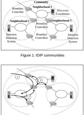
IDIP is an application layer protocol that coordinates intrusion tracking and isolation. IDIP systems are organized into IDIP communities (as shown in Figure 1). Each IDIP community is an administrative domain, with intrusion detection and response functions managed by a component called the Discovery Coordinator. Communities are further organized into IDIP
neighborhoods. These neighborhoods are the collection of
components with no other IDIP component between them. Boundary control devices are members of multiple IDIP neighborhoods.
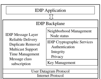
IDIP’s objective is to share the information necessary to enable intrusion tracking and containment. Figure 2 illustrates how IDIP accomplishes intrusion response: (1)when an attack traverses an IDIP-protected network, each IDIP node along the path is responsible for auditing the connection or datagram stream2; (2) when a component detects an intrusion attempt, the detector distributes an attack report to its neighbors who can then help trace the attack path and respond to the intrusion; and (3) these neighbors further distribute the attack description along the path of the attack.
2
For brevity we will henceforth use the term connection generically to refer to both TCP connections and datagram packet streams.
Community Boundary Controllers Discovery Coordinator Intrusion Detection System Neighborhood 2 Intrusion Detection System Neighborhood 1 Neighborhood 3 Boundary Controllers Boundary Controller
Figure 1: IDIP communities
1
2 3
Figure 2: IDIP intrusion response
Each IDIP node makes a local decision as to what type of response (e.g., kill the connection, install filtering rules, disable the user account) is appropriate based on the attack type, attack certainty, attack severity relative to the type of attack and vulnerability of components under attack, what other IDIP nodes have already done, and local policy constraints (e.g., never disable http between 8AM and 4PM). The attack responses are appended to the attack description prior to forwarding the attack description to neighboring IDIP nodes. This enables IDIP to trace the attack back to the edge of the IDIP-protected system, taking appropriate responses at each IDIP node along the attack path. Nodes that receive reports from neighbors determine if they are on the attack path (i.e., whether they have seen the connection described by the attack report) before forwarding the attack report.
Additionally, each IDIP node sends a copy of the attack report (along with the local responses) to the Discovery Coordinator. The Discovery Coordinator can then correlate reports to gain a better overall picture of the situation, and also issue response directives back to individual nodes to either remove an unnecessary
response (e.g., firewall filtering rule), or add a response (e.g., firewall filtering rule along an alternate attack path). The Discovery Coordinator is expected to be co-located with the domain’s network management facilities, providing the Discovery Coordinator with the network global topology, enabling the selection of the optimal points in the network to block harmful connections.
Although Figure 1 depicts only intrusion detection systems and boundary controllers as IDIP components, hosts may also participate in an IDIP system. Hosts can provide more fine-grained responses as they can trace the intrusion back to the process and user initiating the intrusion from the local host. When an intruder is performing an attack after hopping through multiple hosts, IDIP-enabled hosts allow the intrusion to be traced back through these hosts, which is not possible if only boundary controllers participate in the IDIP system.
Note that allowing hosts to participate in IDIP raises two significant issues for the underlying protocol mechanisms: (1) IDIP neighborhoods may grow to be very large, and (2) some of the IDIP nodes may be significantly less “trustworthy” than others because they may have a number of vulnerabilities available for an attacker to use. Because neighborhoods may grow very large, IDIP is designed for multicast operation. At the application level, all neighborhood communication is multicast. This second factor implies that some IDIP nodes may be compromised and potentially used against the system. For this reason, IDIP has features that enable it to distinguish less trustworthy components from more trustworthy components.
3. IDIP Application-Layer Protocol
IDIP is organized into two primary protocol layers: the IDIP application layer and the IDIP message layer. The application layer protocol accomplishes intrusion tracking and containment through three major message types: (1) trace, (2) report, and (3) Discovery Coordinator directive.
An IDIP trace request message is sent when an event or event sequence is detected that is determined to be sufficiently intrusive to warrant a response (which may be to trace the events or to trace and block the events). The
trace request message includes a description of the event,
including a description of the connection used by the intruder. This information is used by each IDIP node that receives the trace request to determine if the attack passed through the node. At each hop in the path, there is a possibility that this description may need to be modified due to network address translation, firewall proxies, or a user passing through a host. The protocol supports translating the attack description by appending a
translation record to the end of the trace message. This allows tracing through hosts, firewalls, and routers. The limitation is that once a non-IDIP component that modifies the connection is reached, the connection can be traced no further. Note that the tracing mechanism is based on what the components have seen and recorded in their audit trail, rather than based on network routing tables or other dynamic network state. This approach also enables tracing of connections that spoof source addresses.
In the trace message, the detector specifies whether this event requires blocking in addition to tracing. Each node receiving the trace message is not obligated to perform the specified blocking rules, but all must perform the trace function. Local nodes can either use the suggested blocking or take some other node-specific action based on local policy. Blocking can be inserted for a limited time or until the system administrator reverses the action. When timed blocking rules are applied, the IDIP software monitors the clock to determine when to remove the blocking rule. Most of the responses taken by IDIP components are capable of being reversed. They are viewed as short-term reactions to provide system administrators time to perform whatever damage assessment and recovery actions are required. In the current implementation, the node responses to trace messages will typically block traffic for a short duration (e.g., a few minutes) to provide time for the Discovery Coordinator to determine an optimal response.
An IDIP report is simply a copy of a trace message that is sent to the Discovery Coordinator by each component that receives a trace message. This enables the Discovery Coordinator to both discover the attack path and to determine an optimal global response based on mission constraints.
To help prevent flooding the IDIP network with trace and report messages, repeated detection events are accumulated at the detector and sent as a single summary report.
Once the Discovery Coordinator has determined an optimal response, it sends directives out to nodes whose response requires altering. There are two types of Discovery Coordinator directives: (1) an undo message requests that the node reverse a previously taken IDIP blocking action (e.g., open up a service that was blocked at a firewall) and (2) a do message to take another action (e.g., extend the duration of a blocking rule). The Discovery Coordinator may request any action supported by the local response component, such as disable a user account or modify a host’s policy. If the Discovery Coordinator is co-located with the system network management infrastructure, then the Discovery
Coordinator can use the network management resources to take actions at non-IDIP components.
The Discovery Coordinator represents a single point of failure in the IDIP system, which makes it a target for denial of service attacks. If the Discovery Coordinator is not available for directing an optimal response, IDIP nodes can take increasingly severe responses to repeated attacks, reducing the reliance of IDIP on Discovery Coordinator actions.
To support communication between the varied IDIP components requires a flexible and extensible language. IDIP uses the Common Intrusion Specification Language (CISL) [6] developed by the Common Intrusion Detection Framework (CIDF) working group as the language for describing attacks and responses. This language includes terms for describing the blocking actions used in the current IDIP implementation, and can be easily extended (by adding new terms) to support additional responses as they are developed. IDIP currently uses only two actions: block and allow. These can be used with various objects (e.g., users, processes, messages, or connections) to cause a number of different responses. Multiple block and allow actions can be specified in one message, each action having its own objects against which to apply the action. As an example, a “block user” message is interpreted as a request to stop that user from doing anything. A “block user and connection” message is interpreted as a request that the user be prevented from using the specified connection. Connection information includes protocol, source address, source port, destination address, and destination port. Any of these parameters may be wildcarded. Response messages can also include a specification of when to start and stop the actions.
4. Cryptographic requirements
Perceived threats to IDIP include falsification of data, one component assuming the identity of another component, or eavesdropping. If a component can masquerade as an IDIP component, or modify IDIP messages, there is an opportunity for both (1) disabling detection and response mechanisms or (2) severe denial of service attacks on the system through malicious manipulation of automated response mechanisms. This is no different than the threat to a system using remote management services as these services become a good target for an adversary. Eavesdropping is a concern primarily in hiding from attackers the details of what was detected and what automated responses are being taken.
The basic requirements for IDIP cryptography include the following.
• Efficient cryptography for messages (e.g., trace messages) that must be sent to each node in a
neighborhood. To minimize computational overhead, encryption and generation of integrity checksums for an IDIP message should occur once for each multicast transmission to the neighborhood. This is important because an IDIP neighborhood could grow quite large. This approach results in the cost of applying cryptography to messages for very large neighborhoods requiring the same amount of time as a message going to a small neighborhood. This approach also supports use of multicast operation for IDIP neighborhoods: each trace message is encrypted once and either unicast or multicast to the neighborhood.
• Support for multicast, including multicast key distribution. For efficient operation, IDIP message layer provides a multicast interface to IDIP applications. To provide cryptographic protection of the multicast IDIP messages requires support from the key distribution mechanisms. That is, the key distribution mechanism must be capable of providing to the multicast group the shared keys used for encryption and generation of integrity checksums. • Minimal impact on IDIP message size, as each IDIP
message must fit within one UDP datagram which is 64 kilobytes.
• Availability on multiple platforms, including Solaris, BSD/OS, Linux, and Windows NT. • Ease of integration.
• Support for multiple multicast groups within a neighborhood (e.g., to segregate key sharing relationships among boundary controllers from those involving less secure hosts).
• The number of messages for key change, due to key refresh or a change in the neighborhood membership should not noticeably affect normal IDIP message flow.
5. Software Architecture
The two primary objectives for the IDIP software architecture were (1) ease of integration with various components and (2) flexibility in modifying the generic component behavior for specific components. The concept supports integration of boundary controllers, network and host-based intrusion detection systems, clients, servers, and network management components.
The IDIP software was designed for portability and is currently executing on Solaris, BSDI, Linux, and
Solaris is a registered trademark of Sun Microsystems, Inc. BSD/OS is a registered trademark of Berkeley Software Design, Inc. Linux is a registered trademark of Linus Torvalds. Windows NT is a registered trademark of Microsoft Corporation.
Windows NT platforms. Operating system dependencies were minimized during the development and have been encapsulated in a single file.
The IDIP software components consist of the IDIP backplane and IDIP applications. IDIP applications developed to date include a generic agent and various Discovery Coordinator applications. These components are described below.
5.1. IDIP Backplane
The IDIP backplane executes on all IDIP nodes, providing reliable, secure communication between IDIP applications. Figure 3 depicts the IDIP backplane showing the message layer, with neighborhood management, cryptographic key management, and cryptographic services. The message layer provides the following services.
• Reliable message delivery, including duplicate message removal.
• Multicast messaging.
• Hop-by-hop message authentication and privacy. • Tracking of neighbor clock delta from the local
clock.
IDIP Message Layer Reliable Delivery Duplicate Removal Multicast Support Time Management Message class subscription Neighborhood Management Node status Key Management
IDIP Cryptographic Services Authentication
Integrity Privacy
User Datagram Protocol Internet Protocol
IDIP Application
IDIP Backplane
Figure 3: IDIP backplane architecture
The IDIP message layer provides a socket-based interface to the application layer, enabling easy integration of new applications. An application subscribes for the message classes it needs, and the message layer delivers all messages of that class (including locally generated messages) to the application. This provides a local multicast capability that allows multiple applications on an IDIP node to share intrusion-related information.
The message layer provides reliable delivery over UDP through a simple acknowledgement mechanism. The
message layer multicast functionality was designed to use IP multicast, but currently uses IP unicast services to send to each neighbor. It provides a multicast interface to the application layer regardless of whether the underlying implementation uses IP multicast or not. The time difference between neighbors is determined and adjusted using round-trip propagation delay of messages and is used by IDIP applications to adjust local time-related portions of messages, such as the time that an attack occurred. Each message has a unique message identifying number, so duplicate messages are not processed.
Neighborhood management includes maintaining status on each IDIP neighbor and forwarding that status to the Discovery Coordinator when it changes. An objective that has not yet been implemented is for this protocol to perform neighbor discovery. The implementation currently uses a list of neighbors provided by the Discovery Coordinator. The neighborhood management function provides other message layer components with notification messages when neighbors are added and deleted, detected via periodic “heartbeat” messages sent between neighbors.
During IDIP development there were no cryptographic mechanisms available that met the full set of requirements described in Section 4. This led to the development of a protocol for IDIP message protection modeled after IP Security (IPSec) [7], with a simple protocol for multicast key distribution. This development was facilitated through use of the open source cryptographic library from OpenSSL [8] for developing IDIP cryptographic services and key management software. This library is available for most platforms, which supports the portability requirements. Keeping the IDIP key management scheme as simple as possible reduced the number of implementation errors.
5.2. IDIP Applications
The IDIP applications manage the IDIP message content that is sent or delivered by the IDIP backplane. One IDIP node in a community executes the Discovery Coordinator application. All IDIP nodes execute an IDIP agent application.
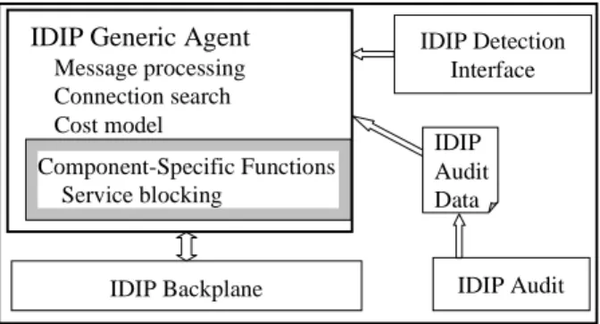
5.2.1. IDIP generic agent. The IDIP generic agent application provides a framework for building component-specific detection and response engines. As shown in Figure 4, the generic agent provides the IDIP application protocol, the interface to local detection and response mechanisms, and the processing of the IDIP audit data.
IDIP Generic Agent Message processing Connection search Cost model Component-Specific Functions Service blocking IDIP Backplane IDIP Detection Interface IDIP Audit IDIP Audit Data
Figure 4: IDIP Generic agent architecture
The generic agent software is designed to minimize the cost of new component integration. Figure 4 shows the IDIP agent application architecture with the component-specific routines highlighted. Figure 4 also shows two additional IDIP processes that support the IDIP agent. • IDIP detection interface. The detection interface
process provides a simple bridge from the local detection system to the socket-based interface of the IDIP agent. The detection system (or a simple wrapper) writes intrusion alerts to a local file in an IDIP standard format (ASCII-formatted strings of name-value pairs). The detection interface process reads the alerts and forwards them over a socket to the generic agent. Using a file interface between the detection system and IDIP has simplified integration by allowing detection component wrappers to be developed and validated without the developer being required to install and run the IDIP software. This interface has also reduced integration debugging costs, as the file provides a good record of the messages between the detection system and IDIP. Detection systems that already produce CISL-formatted output can bypass this process by writing output directly to the IDIP backplane.
• IDIP audit. The audit process monitors connections
to and from the local node and records this traffic in the IDIP audit data format. This software is based on a public domain package (libpcap [9]) for monitoring IP datagrams, which is available on most UNIX
platforms. This process stores connection data in shared memory, which can be read by the generic agent. As connections end, the connection record is written to an audit file. This auditing mechanism is adequate for most IDIP needs, however, when two distinct connections represent the same data stream, additional auditing is required to connect the two data streams. For example, typically a connection through UNIX is a registered trademark of X/Open Company, Ltd.
a firewall proxy will have different source ports for the connections entering and leaving the proxy. The audit process records these as two separate connections. The proxy must record that these two connections are related. For devices that perform network address translation, the address translation mechanism must record that the original and translated connections are related. Likewise, when an attacker hops through multiple hosts, they must record the relationship between the inbound and outbound connections to enable tracing the attack through the host.
The generic agent process is designed to support detection-only components (e.g., network-based detectors), response-only components, and components that perform both detection and response.
• Detection functions. For detection, the generic agent
supports reception of detection events from intrusion detection systems, as well as other significant intrusion-related data (e.g., denied access to local host resources). For pure detection components, no component-specific functions are needed in the generic agent. IDIP trace messages are initiated at a node when a local intrusion detection system detects an anomaly and reports the attack to IDIP via the local detection interface process. For these locally detected attacks, the IDIP agent creates the IDIP
trace message to send to its neighbors. The IDIP trace message includes a description of the anomaly,
a value indicating how certain the detector is of this attack, a severity value based on the potential services lost from this attack, and a requested response. The certainty value is obtained by the agent from a configuration table for the detector. This configuration table represents an estimate of the false positive values for each attack type. One problem encountered is that this value is highly dependent on the local environment and the configuration of the detector, so that it must be calibrated whenever either of these changes. The severity value is generated from a simple “cost model” representing the cost to the system’s mission of losing the services affected by the attack. Penetration attacks are always rated a high severity as they could lead to further lost services if the penetration leads to further attacks. For the trace message to be sent, the severity and certainty must combine to exceed configurable threshold values. The IDIP agent also has a mechanism to accumulate repeated reports of the same detection events into a summary report. The first detection event is reported. Subsequent events are accumulated until either a time or event count threshold is reached, at which point the agent reports
the summary event. This helps prevent a continuing attack from flooding other IDIP nodes.
• Response functions. For response, the generic agent
executes the IDIP application layer protocol and performs local response actions. The agent receives IDIP trace messages from neighbors and directives from the Discovery Coordinator.
¾ Trace message processing. For trace messages, generic agents use the IDIP audit data to determine if they are in the attack path. If so, the agent executes the decision logic to determine the appropriate response. The agent uses a cost model of network resource values to determine the system mission cost of taking the action requested in the trace. If the cost of the response action (in terms of lost services) is less than or equal to the cost of the attack (derived from the certainty and severity in the trace message), then the response is taken. Additional policy constraints can be placed on the response to ensure that critical services are not disabled for long periods of time unless they are already lost to the attack. Although the trace message specifies the detector’s desired blocking action, the local node may perform a different action if local policy determines a better response. Most of the trace-initiated responses in the current implementation are short-lived (on the order of minutes), with the objective of providing the time needed for the Discovery Coordinator to develop a better global response. When attacks continue, however, these trace-initiated responses can be escalated to provide longer-term response actions.
¾ Discovery Coordinator directive message processing. On determining the optimal
system-level response, the Discovery Coordinator sends
do messages to nodes requiring additional
blocking actions, and undo messages to nodes whose initial responses are no longer required. Discovery Coordinator do messages include a specification of both “block” and “allow” rules, which can be used on objects such as connections or users. The combination of both block and allow rules in a single message enables specification of responses such as “block all network traffic except management services.”
5.2.2. Custom IDIP responders. The generic agent supports a flexible set of primitives that can be used to support a number of different responses. Although the generic agent provides most of the functionality required in many response components (e.g., boundary
controllers), the framework allows for building component-specific response engines.
For IDIP agents that perform some response, there are two major component-specific functions required: (1) perform a blocking action, and (2) undo an IDIP blocking action. Note that blocking actions can have a different meaning for different component types. For a firewall agent, “block connection” means killing the connection and adding a filtering rule disallowing similar connections. This requires firewall-specific functions to add the appropriate filtering rule. Within a host the same “block connection” request may require reconfiguring the network services to disable a service.
Beyond these actions, a component may provide other component-specific response routines to perform more elaborate responses in specific situations. These routines are accessed by the generic agent for each trace and Discovery Coordinator directive. For example, in a system running an operating system wrapper technology [10], a suitable response might be to change wrapper policies on specific detection events. CISL provides a flexible language for specifying actions on a number of objects (e.g., process, user, message, connection). Using CISL, new responses can be developed and carried over the IDIP system without changing the infrastructure.
5.2.3. Discovery Coordinator applications. When an
IDIP node sends or processes a trace message it sends a copy of the attack description and responses to the Discovery Coordinator in an IDIP report message. This enables the Discovery Coordinator to know the path of the attack and the response taken by each component along the attack path. The Discovery Coordinator also has access to other system-wide information, such as topology and component vulnerabilities. Thus the Discovery Coordinator has the information necessary to support situation understanding and generation of a system-level optimal response.
The Discovery Coordinator has a very flexible architecture allowing easy integration of new components. This is essential because cyber situation understanding and system-level course of action generation are not yet well understood. As depicted in Figure 5, the Discovery Coordinator can support multiple application processes to perform various system-level functions.
Discovery Coordinator API IDIP Backplane Correlation Engines Response Engines Other Applications Response Manager Discovery Coordinator Core Services
Figure 5: Discovery coordinator application view
Discovery Coordinator core services include those functions that need to be shared throughout the Discovery Coordinator applications to maintain consistent system behavior.
• Data management. • Situation display.
• Access to network management. • Response policy management.
The response concept is for multiple response engines to propose their optimal responses and the response manager to select the response from the component best able to handle the specific situation. Although the architecture supports multiple response engines, the current implementation uses a single response engine that searches for the optimal system response based on a cost model of network resource values. The engine (developed by U. C. Davis) uses the system topology to determine all locations where a specific attack might be blocked, and then determines which location and blocking rule minimizes the overall cost to the system’s mission. This cost model also reasons about user accounts with simple rules that determine when a user account should be disabled based on whether the account appears compromised.
To aid in situation understanding, multiple correlation engines can be employed. The IDIP backplane and Discovery Coordinator application programmers interface (API) allow each correlation engine to receive all attack reports from the system. These correlation engines may also produce attack reports that would be visible by other Discovery Coordinator processes. At this time, four correlation engines have been integrated into the Discovery Coordinator: (1) a simple process that attempts to combine multiple reports of the same event into a single report; (2) Graph-based Intrusion Detection System (GrIDS [11]), which combines reports based on graph algorithms to locate coordinated distributed attacks; (3) a Perl-based component developed by Silicon Defense that
filters out false positives by looking for corroboration of attack reports for events known to represent false alarms; and (4) the Stanford Complex Event Processor [12].
5.3. Integrated Components
A number of components have been integrated with IDIP including boundary controllers, intrusion detection systems, and host security mechanisms. Both COTS products and research prototypes have been used for demonstrations and experiments. Table 1 shows the current components integrated with IDIP.
Table 1: Integrated Components
Boundary Controllers Intrusion Detection Systems Host Based Responders NAI Gauntlet Internet Firewall [13] Net Squared Network Radar [18] NAI Labs Generic Software Wrappers Prototype [10] Secure Computing Corporation Sidewinder Firewall [14] SRI EMERALD BSM and EMERALD FTP Monitors Prototypes [19] TCP Wrappers [23] Linux Router [15] U.C. Davis Graphical Intrusion Detection System Prototype [11] IP Filter [24] NAI Labs ARGuE Prototype [16] Oregon Graduate Institute StackGuard [20] NAI Labs
Multi-Protocol Object Gateway Prototype [17] ORA CORBA Immune System Prototype[21] NAI CyberCop Server and CyberCop Monitor [22] Internet Security Systems RealSecure [2]
Gauntlet is a registered trademark of NAI. Sidewinder is a registered trademark of Secure Computing Corporation. CyberCop is a registered trademark of NAI. RealSecure is a registered trademark of ISS.
6. Future Work
NAI Labs, with Boeing Phantom Works, has recently begun an investigation into the use of active network technology for automated intrusion response. Also, Boeing Phantom Works, with NAI Labs, U.C. Davis, and Silicon Defense, has just been awarded a contract to investigate issues involved in scaling this intrusion detection and response framework to a cyber defense system that span multiple administrative domains.
7. Summary
Research has only recently started in determining appropriate strategies for automated intrusion response. The architecture presented here provides a foundation upon which experimentation in automated intrusion response can be performed. This architecture enables low cost integration of new intrusion detection technologies, new response mechanisms, and new algorithms for determining responses either at a local node level or at a system level.
By providing a mechanism that collects intrusion-related information at a central site, the IDIP architecture also enables correlation of intrusion reports to aid in situation understanding.
Use of CIDF’s CISL as the attack description language provides a flexible approach to expressing new analysis results. This will be particularly helpful in enabling expression of correlation results.
The architecture has already proven useful in supporting integration and experimentation with intrusion detection and response technology within the DARPA research community.
8. References
[1] Network Associates, Active Security, http://www.nai.com/asp_set/products/tns/activesecurity/ acts_intro.asp/.
[2] Internet Security Systems, RealSecure, http://www.iss.net/prod/.
[3] AXENT Technologies Inc., Intruder Alert, http://www.axent.com/product/smsbu/ITA/
[4] Mountain Wave, Inc., “Adaptive Network Security Management”, http://www.mountainwave.com/darpa-report/.
[5] R. Sekar, Y. Cai and M. Segal, “A Specification-Based Approach for Building Survivable Systems”, Proceedings of the 21st National Information Systems Security Conference, Arlington VA, October 1998.
[6] Rich Feiertag, Cliff Kahn, Phil Porras, Dan Schnackenberg, Stuart Staniford-Chen, Brian Tung, “A Common Intrusion Specification Language”, http://www.gidos.org/, June 1999
[7] S. Kent and R. Atkinson, “Security Architecture for the Internet Protocol”, Network Working Group, Request for Comments 2401, November 1998
[8] OpenSSL Project, http://www.openssl.org/.
[9] LBNL’s Network Research Group, “libpcap, the Packet Capture library”, http://ee.lbl.gov/.
[10]T. Fraser, L. Badger, M. Feldman, “Generic Software Wrappers “Hardening COTS Software with Generic Software Wrappers”, Proceedings of the 1999 IEEE Symposium on Security and Privacy, IEEE, Oakland, California, May 1999.
[11]S. Staniford-Chen, S. Cheung, R. Crawford, M. Dilger, J. Frank, J. Hoagland, K. Levitt, C. Wee, R. Yip, D. Zerkle, “GrIDS -- A Graph-Based Intrusion Detection System for Large Networks”, Proceedings of the 19th National Information Systems Security Conference, October 1996. [12]L. Perrochon, W. Mann, S. Kasriel, and D. C. Luckham,
“Event Mining with Event Processing Networks”, Proceedings of the Third Pacific-Asia Conference on Knowledge Discovery and Data Mining. Beijing, China, April 1999.
[13]Network Associates, Gauntlet Firewall, http://www.nai.com/asp_set/products/tns/intro.asp. [14]Secure Computing Corporation, Sidewinder,
http://www.securecomputing.com/. [15]Linux, http://www.linux.org/.
[16]J. Epstein, “Architecture and Concepts of the ARGuE Guard”, to be published in Proceedings of the 15th Annual Computer Security Applications Conference, Phoenix AZ, December 1999.
[17]G. Lamperillo, “Architecture and Concepts of the MPOG”, NAI Labs Reference Number #0768, June 1999.
[18]Net Squared, Network Radar,
http://www.NetSQ.com/Radar/.
[19]Ulf Lindqvist and Phillip A. Porras, “Detecting Computer and Network Misuse Through the Production-Based Expert System Toolset (P-BEST)”, Proceedings of the 1999 IEEE Symposium on Security and Privacy, IEEE, Oakland CA, May 1999.
[20]C. Cowan, C. Pu, D. Maier, H. Hinton, P. Bakke, S. Beattie, A. Grier, P. Wagle, and Q. Zhang, “StackGuard: Automatic Adaptive Detection and Prevention of Buffer-Overflow Attacks”, Proceedings of the 7th USENIX Security Conference, San Antonio TX, January 1998. [21]Odyssey Research Associates, Inc., “Computational
Immunology for Distributed Large Scale Systems”, http://www.oracorp.com/Projects/Current/CompImm.htm [22]Network Associates, CyberCop Intrusion Protection,
http://www.nai.com/asp_set/products/tns/intro.asp. [23]TCP Wrappers http://cs-www.ncsl.nist.gov/tools/tools.htm [24]IP Filter, http://coombs.anu.edu.au/~avalon/ip-filter.html.
![Table 1: Integrated Components Boundary Controllers Intrusion Detection Systems Host Based Responders NAI Gauntlet Internet Firewall [13] Net Squared Network Radar[18] NAI Labs Generic SoftwareWrappers Prototype [10] Secure Computing Corporation Sidewinde](https://thumb-us.123doks.com/thumbv2/123dok_us/9776165.2469360/8.918.467.837.367.930/integrated-components-controllers-intrusion-detection-responders-softwarewrappers-corporation.webp)
