G u i d e f o r S u r v e y B a s e d o n R e l i a b i l i t y - C e n t e r e d M a i n t e n a n c e
GUIDE FOR
SURVEY BASED ON RELIABILITY-CENTERED
MAINTENANCE
DECEMBER 2003 (Updated July 2014 – see next page)
American Bureau of Shipping
Incorporated by Act of Legislature of the State of New York 1862
Copyright 2003
American Bureau of Shipping ABS Plaza
16855 Northchase Drive Houston, TX 77060 USA
Updates
July 2014 consolidation includes:
February 2013 version plus Corrigenda/Editorials
February 2014 consolidation includes:
July 2013 version plus Corrigenda/Editorials
July 2013 consolidation includes:
March 2013 version plus Notice No. 2
March 2013 consolidation includes:
July 2011 version plus Corrigenda/Editorials
July 2011 consolidation includes:
August 2005 version plus Corrigenda/Editorials
August 2005 consolidation includes:
F o r e w o r d
Foreword
In recent years, there has been an increase in the use of proactive maintenance techniques by Owners for repair and maintenance of machinery onboard vessels and offshore structures. The resulting preventative maintenance programs developed as a result of applying these techniques are being used by the vessel’s crew and shore-based repair personnel. There have been numerous advances in condition monitoring technology, trending and increasingly more powerful planned maintenance software as a result of increased business competition. Since 1978, ABS has cooperated with Owners on developing and implementing preventative maintenance programs. In 1984, ABS issued its first Guide for Survey Based on Preventative Maintenance Techniques with subsequent updates in 1985, 1987, 1995 and then inclusion in the Rules for Survey After Construction (Part 7) in mid 2002.
However, machinery systems have continued to become larger and more complex, requiring skilled operators with specialized knowledge of the machinery and systems onboard. This Guide for Survey Based on Reliability-centered Maintenance was developed to provide vessel and other marine structure Owners, managers and operators with a tool to develop a maintenance program using techniques applied in other industries for machinery systems within a maintenance philosophy referred to as Reliability-centered Maintenance (RCM). With the application of RCM principles, maintenance is evaluated and applied in a rational manner that provides the most value to a vessel’s Owner/manager/operator. Accordingly, improved equipment and system reliability onboard vessels and other marine structures can be expected by the application of this philosophy.
An additional purpose of this Guide is to introduce RCM as a part of overall risk management. By understanding the risk of losses associated with equipment failures, a maintenance program can be optimized. This optimization is achieved by allocating maintenance resources to equipment maintenance according to risk impact on the vessel. For example, RCM analysis can be employed to:
• Identify functional failures with the highest risk, which will then be focused on for further analyses • Identify equipment items and their failure modes that will cause high-risk functional failures • Determine maintenance tasks and maintenance strategy that will reduce risk to acceptable levels Reliability-centered maintenance is a process of systematically analyzing an engineered system to understand: • Its functions
• The failure modes of its equipment that support these functions
• How then to choose an optimal course of maintenance to prevent the failure modes from occurring or to detect the failure mode before a failure occurs
• How to determine spare holding requirements
The objective of RCM is to achieve reliability for all of the operating modes of a system. An RCM analysis, when properly conducted, should answer the following seven questions: 1. What are the system functions and associated performance standards?
2. How can the system fail to fulfill these functions? 3. What can cause a functional failure?
4. What happens when a failure occurs?
5. What might the consequence be when the failure occurs? 6. What can be done to detect and prevent the failure?
Typically, the following tools and expertise are employed to perform RCM analyses:
• Failure modes, effects and criticality analysis (FMECA). This analytical tool helps answer Questions 1 through 5.
• RCM decision flow diagram. This diagram helps answer Questions 6 and 7. • Design, engineering and operational knowledge of the system.
• Condition-monitoring techniques.
• Risk-based decision making (i.e., the frequency and the consequence of a failure in terms of its impact on safety, the environment and commercial operations).
This process is formalized by documenting and implementing the following: • The analyses and the decisions taken
• Progressive improvements based on operational and maintenance experience • Clear audit trails of maintenance actions taken and improvements made
Once these are documented and implemented, this process will be an effective system to ensure reliable and safe operation of an engineered system. Such a maintenance management system is called an RCM system. The final result of the RCM analysis is a comprehensive preventative maintenance plan for those equipment items selected for analysis. Therefore, the approach used in the ABS Guide for Survey Based on Preventative Maintenance Techniques (PM Guide) has been applied in this Guide.
This Guide becomes effective immediately upon publication.
T a b l e o f C o n t e n t s
GUIDE FOR
SURVEY BASED ON RELIABILITY-CENTERED
MAINTENANCE
CONTENTS
SECTION 1 General ... 1 1 Application ... 1 2 Objective ... 1 3 Classification Notations ... 1 4 Definitions ... 25 Program Conditions and Administration ... 6
5.1 Age of Vessel ... 6
5.2 Surveys ... 6
5.3 Damages ... 6
5.4 Computerized System ... 6
5.5 Engineering Review ... 6
5.6 Survey and Maintenance Intervals ... 7
5.7 Implementation Survey ... 7
5.8 Spares Holding ... 7
5.9 Sustainment ... 7
5.10 Annual Confirmation Survey ... 7
5.11 Cancellation of Program ... 7
FIGURE 1 Diagram for RCM Program Administration ... 8
SECTION 2 RCM Analysis Requirements ... 9
1 Introduction ... 9
2 RCM Team Setup ... 9
3 Procedures ... 10
4 Initial RCM Analysis Submittal ... 11
4.1 Overview ... 11
4.2 System Definition ... 12
4.3 System Block Diagrams and Functions ... 13
4.4 Identification of Functional Failures ... 14
4.5 Failure Mode Effects and Criticality Analysis (FMECA) ... 14
4.6 Selection of the Failure Management Tasks ... 17
5 Spares Holding Determination ... 19
5.1 Stock-out Effect on End Effects ... 19
6 RCM Sustainment ... 20
6.1 Trend Analysis ... 20
6.2 Maintenance Requirements Document Reviews ... 20
6.3 Task Packaging Reviews ... 20
6.4 Age Exploration Tasks ... 21
6.5 Failures ... 21
6.6 Relative Ranking Analysis ... 22
6.7 Other Activities ... 22
6.8 Sustainment Process Results ... 22
7 Documentation Requirements ... 22
7.1 RCM Analysis Documentation ... 22
7.2 Spares Holding Documentation ... 24
7.3 RCM Sustainment Documentation... 24
8 Special Conditions For Certain Equipment ... 25
8.1 Steam Turbine ... 25
8.2 Internal Combustion Engines ... 25
8.3 Electrical Switch Gear and Power Distribution Panels ... 26
8.4 Permanently Installed Monitoring Equipment ... 26
9 Condition-monitoring Techniques ... 26
TABLE 1 Example Operating Modes and Operating Context ... 27
TABLE 2 Example Function and Functional Failure List ... 28
TABLE 3 Example Bottom-up FMECA Worksheet... 29
TABLE 4 Example Consequence/Severity Level Definition Format... 30
TABLE 5 Probability of Failure (i.e., Frequency, Likelihood) Criteria Example Format ... 32
TABLE 6 Risk Matrix Example Format ... 32
TABLE 7 Failure Characteristic and Suggested Failure Management Tasks ... 33
TABLE 8 Example Maintenance Task Selection Worksheet ... 34
TABLE 9 Summary of Maintenance Tasks ... 35
TABLE 10 Summary of Spares Holding Determination ... 36
FIGURE 1 Diagram for RCM Analysis ... 11
FIGURE 2 Example Partitioning of Functional Groups ... 37
FIGURE 3 Example System Block Diagram ... 38
FIGURE 4 Simplified Task Selection Flow Diagram... 39
FIGURE 5 RCM Task Selection Flow Diagram ... 40
FIGURE 6 Spares Holding Decision Flow Diagram ... 42
FIGURE 6A Example of Use of Spares Holding Decision Flow Diagram ... 43
SECTION 3 Onboard Documentation ... 45
1 Onboard Documentation ... 45
1.1 Condition-monitoring Tasks ... 45
1.2 Planned-maintenance Tasks ... 45
1.3 Combination of Condition-monitoring and Planned-maintenance Tasks ... 45
1.4 Failure-finding Tasks ... 46
1.5 Any Other Applicable and Effective Tasks ... 46
1.6 Spares Holding ... 46
1.7 RCM Sustainment ... 46
SECTION 4 Implementation Survey ... 47
1 General ... 47
SECTION 5 Owner’s Annual RCM Report ... 48
1 General ... 48
2 Condition-monitoring Tasks – Annual ... 48
3 Planned-maintenance Tasks – Annual ... 49
4 For Items Covered by a Combination of Condition-monitoring and Planned-maintenance Tasks ... 49
5 For Items Covered by Failure-finding Tasks ... 49
6 For Items Covered by any other Applicable and Effective Tasks ... 49
7 RCM Sustainment ... 49
8 Report Exceptions ... 49
SECTION 6 Annual Confirmation Survey of RCM Program ... 50
1 Survey Requirements ... 50
SECTION 7 Overhauls and Damage Repairs ... 51
1 Overhauls ... 51
2 Damage Repairs ... 51
SECTION 8 Fees, Information, Offices ... 52
1 Fees ... 52
2 Information ... 52
3 ABS Technical Offices Responsible for RCM ... 52
APPENDIX 1 Additional Resources ... 54
Related Standards ... 54
Related Publications ... 54
APPENDIX 2 Suggested Failure Modes for Marine Machinery Equipment and
Components ... 56
TABLE 1 Electrical Equipment ... 57
TABLE 2 Mechanical Equipment ... 58
TABLE 3 Piping Equipment ... 62
TABLE 4 Control Equipment ... 65
TABLE 5 Lifting Equipment ... 66
TABLE 6 Electrical Components ... 67
TABLE 7 Mechanical Components ... 68
TABLE 8 Piping Components ... 72
TABLE 9 Structural Components ... 74
TABLE 10 Rigging Components... 75
APPENDIX 3 Failure-finding Maintenance Task Interval ... 76
1 Introduction ... 76
2 Statistical View of Hidden Failures ... 76
3 Failure-finding Task Applicability and Effectiveness ... 77
4 Determining Failure-finding Maintenance Task Interval ... 77
4.1 Mathematical Determination of Failure-finding Task Interval ... 78
4.2 Using Guidelines to Determine Failure-finding Task Interval ... 79
5 Failure-finding Maintenance Task Intervals ... 79
TABLE 1 Example of Failure-finding Task Interval Rules ... 79
TABLE 2 Example of Failure-finding Task Intervals Based on MTTF ... 79
TABLE 3 Failure-finding Maintenance Task Interval Estimates ... 80
FIGURE 1 Effect of a Failure-finding Task ... 77
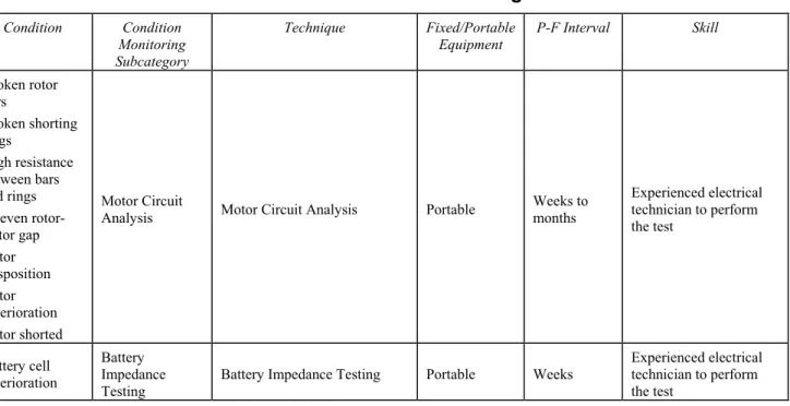
APPENDIX 4 Overview of Condition-monitoring Techniques and Potential-Failure Interval Data ... 81
1 Introduction ... 81
2 Condition Monitoring Categories ... 81
2.1 Corrosion Monitoring ... 82
2.2 Thermography ... 82
2.3 Dynamic Monitoring ... 82
2.4 Oil Analysis and Tribology ... 82
2.5 Nondestructive Testing ... 82
2.6 Electrical Condition Monitoring ... 82
2.7 Performance Monitoring ... 82
2.8 Tabular Listing of Techniques ... 82
3 Guidance for Condition-monitoring Interval Determination ... 83
3.1 Introduction ... 83
3.2 Condition-monitoring Maintenance Task Applicability and Effectiveness ... 83
TABLE 1 Corrosion Monitoring ... 85
TABLE 2 Thermography ... 85
TABLE 3 Dynamic Monitoring ... 86
TABLE 4 Oil Analysis and Tribology ... 87
TABLE 5 Nondestructive Testing ... 89
TABLE 6 Electrical Condition Monitoring (1) ... 91
TABLE 7 Performance Monitoring ... 92
S e c t i o n 1 : G e n e r a l
S E C T I O N
1 General
1
Application
The following are procedures and conditions under which a properly conducted Reliability-centered Maintenance (RCM) analysis and the resulting preventative maintenance plan may be credited as satisfying the requirements of Special Continuous Survey of Machinery.
No preventative maintenance plan supersedes the judgment of an ABS Surveyor, nor does it waive ABS Surveyor attendance for damage, representative overhaul of main engines, generator engines and steering gear, general electrical insulation condition and resistance tests, electrical devices functional tests, reduction gear teeth examinations, hydrostatic tests of pressure vessels, tests and verification of safety devices such as relief valves, overspeed trips, emergency shut-offs, low-oil pressure trips, etc., as required by the ABS
Rules for Building and Classing Steel Vessels (Steel Vessel Rules), including the ABS Rules for Survey After Construction – Part 7 (Rules for Survey).
It is a prerequisite that the machinery in this program be on a Special Continuous Survey of Machinery (CMS) cycle.
2
Objective
The objective of this Guide is to provide requirements which reduce the risk to personnel, the vessel or marine structure, other vessels or structures and the environment and which reduce the economic consequences due to a machinery failure which may otherwise occur more frequently if a rational maintenance strategy, as provided for by this Guide, was not applied. This is achieved by applying the analysis methodology provided in this Guide to develop a rational maintenance plan. By using RCM principles, maintenance is evaluated and applied in a rational manner. Functional failures with the highest risk are identified and then focused on. Equipment items and their failure modes that will cause high-risk functional failures are identified for further analyses. Maintenance tasks and maintenance strategies that will reduce risk to acceptable levels are determined. Spare parts inventories are determined based on the maintenance tasks developed and a risk assessment. An RCM sustainment procedure is instituted to continually monitor and optimize maintenance. Accordingly, improved equipment and system reliability can be expected.
With an effective preventative maintenance plan, credit towards the requirements of Special Continuous Survey of Machinery may be provided.
3
Classification Notations
(1 July 2013)
The RCM Program is to be approved by an ABS Technical Office. Upon completion of a satisfactory Implementation Survey, a “Certificate of Approval for Reliability-centered Maintenance Program” is to be issued by the attending Surveyor. A notation, if appropriate, will be entered in the Record.
In general, any machinery systems subject to Special Periodical Survey listed in 7-6-2/3 “Special Periodical Surveys – Machinery”, Section 7-8-2 “Shipboard Automatic and Remote-control Systems – Special Periodical Surveys”, or applicable sections in Part 7, Chapter 9 “Survey Requirements for Additional Systems and Services” of the Rules for Survey may be selected for RCM analysis and development of a preventative maintenance plan. There are other Special Periodical Survey requirements listed in other Rules and Guides not listed here for which machinery systems may be selected for analysis. The vessel’s Owner may specifically request review of other machinery not subject to Special Periodical Survey.
Section 1 General
When the RCM Program is approved for the equipment related to:
i) The propulsion system, including as applicable: prime mover(s), reduction gears, shafting, propeller or other thrusting device, all auxiliary systems providing, cooling, control, electrical power, exhaust, fuel, lubrication and equipment related to the steering or other directional control system, the RCM Program will be assigned and distinguished in the Record with the class notation RCM (PROP). ii) The cargo handling (cargo pumps, associated piping for internal and independent tanks) and safety
equipment (i.e., inert gas system, vapor emission control) for a tanker, liquefied gas carrier or chemical carrier, the RCM Program will be assigned and distinguished in the Record with the class notation RCM (CARGO).
iii) When the RCM Program is approved for systems and equipment used in connection with drilling and the drilling system and the drilling system is in compliance with the Guide for the
Classification of Drilling Systems, the RCM Program will be distinguished in the Record with the class notation RCM (CDS).
iv) When the RCM Program is approved for the Production or Facilities systems and equipment on an
FPSO or FSO, the RCM Program will be distinguished in the Record with the class notation RCM
(PFE).
The Owner may select other particular systems or equipment for which RCM analysis is desired. Any machinery items not covered by the RCM analysis are to be surveyed and credited in the usual way in accordance with the Rules for Survey.
4
Definitions
The following definitions are applied to the terms used in this Guide.
ABS Recognized Condition Monitoring Company. The reference to this term refers to those companies whom ABS has identified as an External Specialist. Please refer to Subsection 8/2.
Baseline Data. The baseline data refer to condition monitoring indications – usually vibration records on rotating equipment – established with the equipment item or component operating in good order, when the unit first entered the Program; or the first condition-monitoring data collected following an overhaul or repair procedure that invalidated the previous baseline data. The baseline data are the initial condition-monitoring data to which subsequent periodical condition-condition-monitoring data is compared.
Cause. See failure cause.
Component. The hierarchical level below equipment items. This is the lowest level for which the component: can be identified for its contribution to the overall functions of the functional group; can be identified for its failure modes; is the most convenient physical unit for which the preventative maintenance plan can be specified.
Condition Monitoring. Condition monitoring are those scheduled diagnostic technologies used to monitor machine condition to detect a potential failure. Also referred to as an on-condition task or predictive maintenance.
Confidence. Confidence is the analyst’s/team’s certainty of the risk evaluation.
Consequence. The way in which the effects of a failure mode matter. Consequence can be expressed as the number of people affected, property damaged, amount of oil spilled, area affected, outage time, mission delay, dollars lost, etc. Regardless of the measure chosen, the consequences are expressed “per event”.
Corrective Measures. Corrective measures are engineered or administrative procedures activated to reduce the likelihood of a failure mode and/or its end effect.
Criticality. Criticality is a measure of risk associated with the failure mode and its effects. The risk can be measured qualitatively (e.g., high, medium, low) or quantitatively (e.g., $15,000 per year).
Current Likelihood (Frequency). The current likelihood (or frequency) of a failure mode occurring is based on no maintenance being performed or in the case of existing preventative maintenance plans, the
Section 1 General
Current Risk. The resulting risk that results from the combination of the severity and the current likelihood
(severity times likelihood).
Effects. See failure effects.
End Effects. See failure effects.
Environmental Standards. Environmental standards are international, national and local laws and regulations or industry standards that the vessel must operate in conformance with.
Equipment items. The hierarchical level below systems comprised of various groups of components.
Event. An event is an occurrence that has an associated outcome. There are typically a number of potential outcomes from any one initial event ranging in severity from minor (trivial) to critical (catastrophic), depending upon other conditions and add-on events.
Evident Failure Mode. A failure mode whose effects become apparent to the operators under normal circumstances if the failure mode occurs on its own.
Failure Cause. The failure cause is the basic equipment failure that results in the failure mode. For example, pump bearing seizure is one failure cause of the failure mode pump fails off.
Failure Characteristic. The failure characteristic is the failure pattern (i.e., wear-in, random, wear-out) exhibited by the failure mode.
Failure Effects. Failure effects are the consequences that can result from a failure mode and its causes. • Local Effect. The initial change in the system operation that would occur if the postulated failure mode
occurs.
• Next higher Effect. The change in condition or operation of the next higher level of indenture caused by the postulated failure mode. This higher-level effect is typically related to the functional failure
that could result.
• End Effect. The overall effect on the vessel that is typically related to the consequences of interest for the analysis (loss of propulsion, loss of maneuverability, etc.). For the purposes of this Guide, the term
End Effects applies only to the total loss or degradation of the functions related to propulsion and directional control including the following consequences: loss of containment, explosion/fire, and/or safety occurring immediately after or a short time thereafter as a result of a failure mode. For offshore activities, these may be extended to include functions related to drilling operations, position mooring, hydrocarbon production and processing, and/or import and export functions.
Failure-finding Task. A failure-finding task is a scheduled task used to detect hidden failures when no
condition-monitoring or planned-maintenance task is applicable. It is a scheduled function check to determine whether an item will perform its required function if called upon.
Failure Management Strategy. A failure management strategy is a proactive strategy to manage failures and their effects to an acceptable risk. It consists of proactive maintenance tasks and/or one-time changes.
Failure Mode. The failure mode describes how equipment can fail and potentially result in a functional failure. Failure mode can be described in terms of an equipment failure cause (e.g., pump bearing seizes), but is typically described in terms of an observed effect of the equipment failure (e.g., pump fails off).
FMECA. The acronym for Failure Mode Effects and Criticality Analysis.
Frequency. The frequency of a potential undesirable event is expressed as events per unit time, usually per year. The frequency should be determined from historical data if a significant number of events have occurred in the past. Often, however, risk analyses focus on events with more severe consequences (and low frequencies) for which little historical data exist. In such cases, the event frequency is calculated using risk assessment models.
Section 1 General
Function. A function is what the functional group, systems, equipment items and components are designed to do. Each function should be documented as a function statement that contains a verb describing the function, an object on which the function acts, and performance standard(s).
• Primary Function. A primary function is directly related to producing the primary output or product from a functional group/system/equipment item/component.
• Secondary Function. A secondary function is not directly related to producing the primary output or product, but nonetheless is needed for the functional group/system/equipment item/component.
Functional Failure. A functional failure is a description of how the equipment is unable to perform a specific function to a desired level of performance. Each functional failure should be documented in a functional failure statement that contains a verb, an object and the functional deviation.
Functional Group. A hierarchical level addressing propulsion, maneuvering, electrical, vessel service, and navigation and communications functions.
Hazard. Hazards are conditions that may potentially lead to an undesirable event.
Hidden Failure Mode. A failure mode whose failure effects do not become apparent to the operators under normal circumstances if the failure mode occurs on its own.
Indications (Failure Detection). Indications are alarms or conditions that the operator would sense to detect the failure mode.
Level of Indenture. A relative position within a hierarchy of functions for which each level is related to the functions in the level above. For the purposes of this Guide, the levels of indenture in descending order are: functional group, systems, subsystems, equipment items and components.
Likelihood. See frequency.
One-time Change. One-time change is any action taken to change the physical configuration of a component, an equipment item or a system (redesign or modification), to change the method used by an operator or maintenance personnel to perform an operation or maintenance task, to change the manner in which the machinery is operated or to change the capability of an operator or maintenance personnel, such as by training.
Operating Context. The operating context of a functional group is the circumstances under which the functional group is expected to operate. It must fully describe: the physical environment in which the functional group is operated, a precise description of the manner in which the functional group is operated and the specified performance capabilities of the functional group.
Operating Mode. An operating mode is the operational state the vessel or marine structure is in. For example, cruising at sea, entering or departing a port.
P-F Interval. The Potential Failure interval is the time interval between the point at which the onset of failure can be detected and the point at which functional failure occurs. A condition-monitoring task should be performed at less than half of this interval.
Parallel Redundancy. Parallel redundancy applies to systems/equipment items operating simultaneously. Each system has the capability to meet the total demand. In the event of a functional failure in one system/equipment item, the remaining system/equipment item will continue to operate, but at a higher capacity. For some arrangements, standby systems/equipment items may also be in reserve.
Performance and Quality Standards. Performance and quality standards are the requirements functional groups/systems/equipment items/components are to operate at, such as minimum/maximum power or pressure, temperature range, fluid cleanliness, etc.
Planned Maintenance. For the purposes of this Guide, planned maintenance is a scheduled maintenance task that entails discarding a component at or before a specified age limit regardless of its condition at the time. It also refers to a scheduled maintenance task that restores the capability of an item at or before a specified age limit, regardless of its condition at the time, to a level that provides an acceptable probability of survival to the end of another specified interval. These maintenance tasks are also referred to as “scheduled discard” and “scheduled restoration”, respectively.
Section 1 General
Preventative Maintenance Plan. The preventative maintenance plan consists of all the maintenance tasks identified as necessary to provide an acceptable probability of survival to the end of a specified interval for the machinery systems. In IACS UR Z20, this is referred to as a “Planned Maintenance Scheme”.
Proactive Maintenance Task. A proactive maintenance task is implemented to prevent failures before they occur, detect the onset of failures or discover failures before they impact system performance.
Projected Likelihood. The likelihood (or frequency) of a failure mode occurring based on a maintenance task being performed or a one-time change implemented.
Projected Risk. The resulting risk that results from the combination of the consequence and the projected likelihood.
Random Failure. Random failure is dominated by chance failures caused by sudden stresses, extreme conditions, random human errors, etc. (i.e., failure is not predictable by time).
Risk. Risk is composed of two elements, frequency and consequence. Risk is defined as the product of the frequency with which an event is anticipated to occur and the severity of the consequence of the event’s outcome.
Risk Matrix. A risk matrix is a table indicating the risk for an associated frequency and consequence severity.
Run-to-failure. Run-to-failure is a failure management strategy that allows an equipment item/component
to run until failure occurs, and then a repair is made.
Safeguards. See corrective measures.
Safety Standards. Safety standards address the hazards that may be present in an operating context and specify the safeguards (corrective measures) that must be in place for the protection of the crew and vessel.
Servicing and Routine Inspection. These are simple tasks intended to (1) ensure that the failure rate and failure pattern remain as predicted by performing routine servicing (e.g., lubrication) and (2) spot accidental damage and/or problems resulting from ignorance or negligence. They provide the opportunity to ensure that the general standards of maintenance are satisfactory. These tasks are not based on any explicit potential failure condition. Servicing and routine inspection may also be applied to items that have relatively insignificant failure consequences, yet should not be ignored (minor leaks, drips, etc.).
Severity. When used with the term consequence, severity indicates the magnitude of the consequence.
Special Continuous Survey of Machinery. The requirements for Special Continuous Survey of Machinery are listed in 7-2-1/7 Continuous Surveys (Vessels in Unrestricted Service) and 7-2-2/9 Continuous Surveys (Vessels in Great Lakes Service) of the Rules for Survey.
Special Periodical Survey – Machinery. The requirements for a conventional Special Periodical Survey – Machinery are listed in 7-2-2/7 “Vessels in Great Lakes Service – Special Periodical Surveys”; 7-2-3/5 “Vessels in Rivers and Intracoastal Waterway Service – Special Periodical Surveys”; 7-6-2/3 “Special Periodical Surveys – Machinery” (3.1 “All Vessels”, 3.3 “Tankers”); 7-6-3/1 Vessels in Great Lakes Service – Special Periodical/Continuous Survey-Machinery-Year of Grace ; 7-8-2 “Shipboard Automatic and Remote-control Systems – Special Periodical Surveys”; Part 7, Chapter 9 “Survey Requirements for Additional Systems and Services” (Cargo Refrigeration, Hull Condition Monitoring System, Quick Release System, Thrusters and Dynamic Positioning System, and Vapor Emission Control System) of the
Rules for Survey. There are special periodical survey requirements in other Rules and Guides for specific vessel types, services and marine structures not listed here.
Subsystems. An additional hierarchical level below system, comprised of various groups of equipment items for modeling complex functional groups.
Systems. The hierarchical level below functional group, comprised of various groups of equipment items.
Wear-in Failure. Wear-in failure is dominated by “weak” members related to problems such as manufacturing defects and installation/maintenance/startup errors. It is also known as “burn in” or “infant mortality”.
Section 1 General
5
Program Conditions and Administration
A diagram for the administration of the RCM Program is shown in Section 1, Figure 1. A summary of the Program requirements for each step of the process is provided along with a reference to the applicable Section in this Guide.
For a Reliability-centered Maintenance Program in lieu of a conventional Special Continuous Survey of Machinery to be accepted, the following conditions must be met:
5.1 Age of Vessel
There is no limit on the age of a vessel when entered into the program. However, a vessel applying for entrance into the Program will be subject to a review of the vessel’s Survey Status records to ascertain the historical performance of the machinery which could affect the RCM Program. Provided there are no historical problems related to the maintenance of machinery (e.g., unscheduled repairs, inability to meet performance requirements), the vessel will be considered eligible. If a machinery item is identified with unsatisfactory performance (see Subsection 7/2), the vessel may still be considered eligible, provided more frequent surveys of the item are conducted, and/or a one-time change is made, resulting in satisfactory performance and confirmed by survey.
5.2 Surveys
Surveys related to the vessel are to be up-to-date, without outstanding recommendations which would affect machinery enrolled in the RCM Program. The machinery in the program is to be on a Special Continuous Survey of Machinery (CMS) cycle.
If the vessel is not on CMS, the Owner is to be advised that the vessel is to be entered in CMS. For machinery for which an outstanding recommendation exists, confirmation is to be made that repairs have been performed, or if repairs have not been performed, the Owner is to be notified that an outstanding recommendation exists.
Any machinery items not covered by the RCM Program are to be surveyed and credited in the usual way in accordance with the Rules for Survey.
5.3 Damages
There is to be no record of unrepaired damage to the vessel or its machinery which would affect the vessel’s ability to participate in the RCM Program.
5.4 Computerized System
The RCM analysis and preventative maintenance plan is to be programmed into and maintained by a computerized system. Details of the computerized system are to be submitted to the responsible ABS Technical Office (as listed in Subsection 8/3) for approval. It is preferable that analyses and reports required in accordance with the RCM Program be submitted or available in an electronic format with the capability to be copied to CD-ROM or other acceptable electronic storage medium.
Computerized systems are to include back-up devices such as disks/tapes or CD-ROMs which are to be updated at regular intervals.
5.5 Engineering Review
Where enrollment of machinery in the RCM Program is requested, the initial RCM analysis and preventative maintenance plan are to be submitted to the responsible ABS Technical Office (as listed in Subsection 8/3) for approval. If additional equipment is enrolled in the RCM Program, the analyses are to be submitted to the responsible ABS Technical Office which performed the initial review. The requirements for the documentation to be submitted are listed in Section 2.
Section 1 General
5.6 Survey and Maintenance Intervals
The resulting preventative maintenance plan will list maintenance tasks to be carried out. The intervals between routine maintenance, testing or overhauls are based on recommendations by manufacturers, documented operator's experience, application of failure-finding maintenance task interval and overview of condition-monitoring techniques, and/or potential-failure interval data (Appendices 3 and 4), where applicable. In general, the intervals for the preventative maintenance plan are not to exceed those specified for Special Continuous Survey of Machinery (CMS). However, for components where the maintenance is based on running hours, longer intervals may be accepted as long as the intervals are based on the manufacturer’s recommendations.
However, if an approved preventative maintenance program applying condition-monitoring techniques is in effect, the machinery survey intervals based on the CMS cycle period may be extended.
5.7 Implementation Survey
The implementation survey is to be carried out by the attending Surveyor within one year from the date of the approval letter approving the RCM analysis and preventative maintenance plan, as issued by the responsible ABS Technical Office. The requirements for the implementation survey are listed in Section 4.
When this survey is carried out and the implementation found to be in order, a report confirming the implementation of the RCM Program is to be submitted by the attending ABS Surveyor, and the system may be put into service. A class notation will be assigned and distinguished in the Record, if appropriate, in accordance with Subsection 1/3.
5.8 Spares Holding
The Surveyor is to verify that an effective, computerized spares holding inventory and ordering system is established onboard at the Implementation Survey and at subsequent Annual Confirmation Surveys (see Sections 4 and 6).
5.9 Sustainment
An effective RCM sustainment program will collect, analyze, review and respond to in-service data throughout the life of the vessel so as to continually improve the preventative maintenance plan (see Subsection 2/6). The results of the sustainment process are to be submitted to the attending Surveyor at the Annual Confirmation Survey. If the RCM analysis or preventative maintenance plans are revised as a result of the sustainment process, the analyses are to be submitted to the responsible ABS Technical Office that performed the initial review.
5.10 Annual Confirmation Survey
Simultaneously with each Annual Survey of Machinery for vessels on the RCM program, an Annual Confirmation Survey is to be performed by the attending Surveyor. This survey is to verify that the program is being correctly operated and that the machinery has been functioning satisfactorily since the previous survey.
5.11 Cancellation of Program
The survey arrangement for machinery under the RCM Program may be cancelled by ABS if the program is not being satisfactorily carried out, either from the maintenance records or the general condition of the machinery, or when the agreed intervals between overhauls are exceeded.
Sale or change of management of the vessel or transfer of class is to be cause for reconsideration of the approval.
The Owner may at any time cancel the survey arrangement for machinery under the RCM Program by informing ABS in writing. For this case, items which have been inspected under the program since the last Annual Survey may be credited for class at the discretion of the Surveyor. However, ABS will determine future survey requirements for machinery formerly enrolled in the RCM Program.
Section 1 General
FIGURE 1
Diagram for RCM Program Administration
General Program Enrollment Requirements:
No existing damage/unrepaired damage/historical problems with equipment,
Enrolled on Special Continuous Survey of Machinery (CMS) cycle, Surveys current,
RCM/Maintenance System is Electronic
Submit Initial RCM Analysis to ABS Technical Office
ABS Engineering Review of: RCM Analysis
Preventative Maintenance Plan with Current Data Spares Holding Determination
RCM Sustainment Process
Onboard Documentation
Current preventative maintenance records
Reference documentation (trend analysis, maintenance manuals, calibration data)
Implementation
Survey
RCM Program implemented per approved analysis Required documentation for Annual Confirmation can be produced
Personnel familiar with Program Sustainment process in effect
Owner's Annual RCM Report
Document preventative maintenance performed Document sustainment activities
Spare parts inventory/ordering Report findings of exceptions Submit revised RCM Analysis (if applicable)
Annual Confirmation Survey
Review of Owner's Annual RCM Report Examination of performance/maintenance records
Discretionary function tests
Credit to CMS for machinery maintained per Program
Subsection 1/5
Section 2
Section 3
Section 4
Section 5
Section 6
S e c t i o n 2 : R C M A n a l y s i s R e q u i r e m e n t s
S E C T I O N
2 RCM Analysis Requirements
1
Introduction
The analysis consists of a Failure Mode Effects and Criticality Analysis (FMECA), a preventative maintenance plan, a spares holding plan and a sustainment process. The RCM sustainment process is to be designed so as to continually review and refine the preventative maintenance plan as the machinery ages, modifications are made during its service life or the operating context of the vessel changes.
The primary objective of RCM analysis is to provide a comprehensive, systematic and documented investigation which establishes important failure conditions of the machinery system(s), maintenance tasks or system/equipment redesigns chosen to reduce the frequency of such occurrences, and the rationale for spares inventory. There are special conditions for steam turbines, internal combustion engines, electrical switchgear and power distribution panels and permanently installed monitoring equipment (see Subsection 2/8). Additional benefits for the Owner/Operator of the vessel or marine structure which are beyond the scope of this Guide are:
• To provide data to generate comprehensive training, operational and maintenance programs and documentation; and
• To provide the results of the study into the vessel’s failure characteristics so as to assist in an assessment of levels of risk proposed for the vessel’s operation.
The analysis is to be conducted for all equipment and systems proposed for enrollment in the RCM Program. The Initial RCM Analysis is to be submitted to the responsible ABS Technical Office for approval. Subsequently, Annual RCM Sustainment Analyses, if applicable, are to be prepared for review by the attending Surveyor at the Annual Confirmation Survey. If additional equipment is enrolled in the RCM Program, or the preventative maintenance plan is revised as a result of sustainment processes, the analyses are to be submitted to the responsible ABS Technical Office which reviewed the Initial RCM Analysis.
Additional standards and reference publications are listed in Appendix 1.
2
RCM Team Setup
An RCM-based preventative maintenance plan is best performed by a multi-disciplinary team that synergistically brings together different perspectives and technical strengths. A team approach ensures that all required information that is available within the vessel or marine structure and/or organization is considered in the RCM analysis, as well as providing a wider perception of the risks of failure and effective maintenance tasks.
The specific composition of the team varies depending on the complexity of the vessel or marine structure, scope of the RCM Program and any applicable regulatory requirements. Some of the disciplines will be called from within or outside the organization as advisors, but a core team is essential for continuity. The RCM team should have the expertise to identify and analyze all of the factors and their implications to machinery function along with explosion/fire, loss of containment and safety. If during the RCM risk prioritization, failure scenarios are inaccurately determined to have low risk, the RCM analysis could potentially affect maintenance efforts of related components, thus resulting in a hazardous situation.
Section 2 RCM Analysis Requirements
The RCM team will typically consist of individuals with experience and technical knowledge in the following disciplines:
i) Maintenance and inspection of machinery
ii) Degradation and failure mechanisms of machinery
iii) Reliability
iv) Operations
v) Risk analysis
vi) Production process hazards (if applicable)
vii) Safety and health
viii) Materials of construction
Participation in the team of a representative with knowledge of RCM analyses in other vessels/marine structures will ensure consistency throughout the organization and/or industry, as well as provide wider experience of risks and preventative maintenance practices.
Among the duties of the RCM team members are:
i) To participate and proactively contribute in all required risk analysis and RCM meetings to ensure their knowledge is easily tapped for the RCM analyses
ii) To validate the quality and veracity of the information available
iii) To perform their specific RCM tasks, keeping in mind the end goals of the RCM Program
3
Procedures
The procedures necessary to perform the RCM analysis are shown in Section 2, Figure 1, along with the cross-reference to the corresponding Subsection/Paragraph of this Section.
Section 2 RCM Analysis Requirements
FIGURE 1
Diagram for RCM Analysis
Identify operating modes and corresponding operating context
Define vessel systems
Develop system block diagrams and identify functions
Identify functional failures
Conduct Failure Mode Effects and Criticality Analyis (FMECA)
Select failure management tasks
Determine spare parts holdings
Develop RCM sustainment process
Document requirements for RCM
Preventative Manitenance Plan, Spare Parts Plan, Sustainment Process
Ready for Implementation of RCM Onboard
Paragraph 2/4.1
Paragraph 2/4.2
Paragraph 2/4.3
Paragraph 2/4.4
Paragraph 2/4.5
Paragraph 2/4.6
Subsection 2/5
Subsection 2/6
Subsection 2/7
4
Initial RCM Analysis Submittal
4.1 Overview
A detailed study of the systems subject to RCM analysis is to be made through the use of system drawings; equipment item drawings; documents containing maintenance requirements for systems, equipment items or components; and operator experience.
All operating modes, as applicable, within normal design environmental conditions are to be considered. The following operating modes are typical for ships:
Section 2 RCM Analysis Requirements
• Normal seagoing conditions at full speed
• Maximum permitted operating speed in congested waters • Maneuvering alongside
• Cargo handling
The following operating modes are typical for mobile offshore drilling units and offshore oil and gas production facilities:
• Drilling operations
• Position mooring or station keeping • Relocation/Towing
• Hydrocarbon production and processing • Import and export functions
The functional interdependence of the selected systems within functional groups shall be described through the use of block diagrams (see Paragraph 2/4.3) or fault-tree diagrams or in a narrative format to enable failure effects to be understood. A list of failure modes for each of the systems to be analyzed is to be developed (see Paragraph 2/4.4).
To properly define operating characteristics, the various operating modes for the vessel must be identified. Next, the operating modes are used to define the operating context for each functional group.
For each operating mode, the operating context under which the functional group is expected to operate is to be fully described as follows:
• The physical environment in which the functional group is operated • A precise description of the manner in which the functional group is used
• The specified performance requirements of the functional group as well as the required performance of any additional functional groups within which the functional group is interfaced
The development of the operating context is to consider system arrangements, performance or quality standards, environmental standards, safety standards and manner of operation. Operating contexts are to be developed for each level of indenture. An example of an operating mode, along with its operating context, is provided in Section 2, Table 1.
4.2 System Definition
Each system selected for RCM analysis is to be defined. The system definition involves (1) partitioning the vessel’s functional groups into systems, subsystems (as necessary due to complexity), equipment items and components, and (2) further development of the narrative description described in Paragraph 2/4.1 for each functional group, system, equipment item and component. An example partitioning for a vessel’s machinery is provided in Section 2, Figure 2.
A narrative description for each level of indenture and the corresponding functional requirements is to be developed, providing the following information:
• A general description of operation and structure
• The functional relationship among the system/equipment items/components
• Acceptable functional performance limits of the system/equipment items/components for each operating mode considered in Paragraph 2/4.1
• Constraints
The partitioning is to be performed using a top-down approach until a level of indenture is reached for which functions are identified with equipment items or components. The level of indenture should be such that the equipment item or component:
Section 2 RCM Analysis Requirements
• Can be identified for its contribution to the overall functions of the functional group • Can be identified for its failure modes
• Is the most convenient physical unit for which maintenance can be specified
4.3 System Block Diagrams and Functions
The functions for the functional groups, systems, equipment items and components are to be identified. When identifying functions, the applicable operating modes and the operating context is to be listed. All functions are to be identified.
Function lists may be submitted by providing a list similar to that shown in Section 2, Table 2.
Block diagrams are to be developed showing the functional flow sequence of the functional group, both for technical understanding of the functions and operation of the system and for subsequent analysis. As a minimum, the block diagram is to contain:
• The partitioning of the functional group into systems, equipment items and components
• All appropriate labeled inputs and outputs and identification numbers by which each system is consistently referenced
• All redundancies, alternative signal paths and other engineering features that provide “fail-safe” measures It may be necessary to create a different set of block diagrams for each operational mode.
An example system block diagram is shown in Section 2, Figure 3.
When identifying the function, the performance standard is to describe the minimum acceptable requirement for the operating context rather than the system or component’s design capability. Performance standards must be clearly defined or quantified, as they are used to define failure. Functions are to be categorized, as shown in Section 2, Table 2, as follows:
Primary functions. These functions are the reasons why the functional group/system/equipment item/component exist. For example, the primary function of the Propulsion Functional Group is to provide propulsion for a vessel; the primary function of the system, diesel engine, is to provide power to propel a vessel.
Secondary functions. These functions are in addition to the primary functions. Examples of secondary functions for a diesel engine in the Propulsion Functional Group include emissions requirements for exhaust gases, fuel efficiency requirements and safety systems, such as overspeed trips and cylinder relief valves. The following functional categories are listed with some examples, as an aid in determining secondary functions for systems to be analyzed:
• Environment integrity. Equipment fluid or gaseous emissions limits subject to MARPOL or other regulations
• Safety, structural integrity. Vibration, structural deflection, limits; safety of human operators/maintenance personnel
• Control, containment, comfort. Equipment control, containment of fluids/gases in system, personal comfort of personnel
• Appearance. Appearance of equipment to the operators/public
• Protection. Devices to protect equipment from overspeed, high pressure or high temperature • Economy, efficiency. Fuel efficiency, lubricating oil consumption
• Supplementary functions. Other functions unique to the functional group/system/equipment item/ component
Section 2 RCM Analysis Requirements
4.4 Identification of Functional Failures
A list of functional failures for each function identified in Paragraph 2/4.3 is to be identified for each functional group, system, equipment item and component. Functional failures are to be identified using the following suggested failures, as appropriate:
• No or none of the function
• Less than prescribed output of function • More than prescribed output of function • Intermittent operation of the function • Premature operation of the function
• Failure to operate function at a prescribed time
• Failure to cease operation of the function at a prescribed time • Other functional failures appropriate for the functional group
Each functional failure is to be documented in a functional failure statement that contains a verb, object and the functional deviation. The functional failures are to be shown with the function lists similar to the example list in Section 2, Table 2.
4.5 Failure Mode Effects and Criticality Analysis (FMECA)
The FMECA shall be considered using the bottom-up approach, starting from the lowest level of indenture identified during the system partitioning performed in Paragraph 2/4.2. A sample bottom-up FMECA format is shown in Section 2, Table 3.
The FMECA procedure is divided into the following steps:
• Identify all potential failure modes and their causes (Subparagraph 2/4.5.1) • Evaluate the effects on the system of each failure mode (Subparagraph 2/4.5.2) • Identify failure detection methods (Subparagraph 2/4.5.3)
• Identify corrective measures for failure modes (Subparagraph 2/4.5.4)
• Assess the frequency and severity of important failures for criticality analysis, where applicable (Subparagraph 2/4.5.5)
4.5.1 Identification of Failure Modes
A failure mode is the manner by which a failure is observed. It generally describes the way the failure occurs and its impact on the equipment or system. All of the equipment item or component-related causes of the identified failure modes are to be identified. Example lists of failure modes for various equipment items and components are provided in Appendix 2. The user is cautioned that other failure modes may exist that are not listed in Appendix 2. The failure modes listed in Appendix 2 can be used to describe the failure of any equipment item or component in sufficiently specific terms. When used in conjunction with performance specifications governing the inputs and outputs on the system block diagram, all potential failure modes can thus be identified and described. Failure shall be assumed by one possible failure mode at a time with the exception of “hidden failures” in which a second failure must occur in order to expose the “hidden failure”.
A failure mode in an equipment item or component could also be the failure cause of a system failure. Since a failure mode may have more than one cause, all potential independent causes for each failure mode shall be identified.
Section 2 RCM Analysis Requirements
The failure characteristic for the failure mode is to be identified as follows:
• Wear-in failure is to be used for failures associated with manufacturing defects and installation, maintenance or startup errors;
• Random failure is to be used for failures associated with random failures caused by sudden stresses, extreme conditions, random human errors or any failure not predictable by time; and • Wear-out failure is to be used for failures associated with end-of-useful life issues for equipment. The failure mode may have multiple failure characteristics. The identification of the failure characteristic(s) is used in Paragraph 2/4.6 to aid in the selection of appropriate failure management task(s).
4.5.2 Failure Effects
The effects of the failure for each failure mode are to be listed as follows:
• The Local Effect is to describe the initial change in the equipment item or component operation when the failure mode occurs; failure detection methods, if any, are to be identified and availability of standby system/equipment to provide the same function.
• The Functional Failure is to describe the effect of the failure mode on the system or functional group; such as potential physical damage to the system/equipment item; or potential secondary damage to either other equipment items in the system or unrelated equipment items in the vicinity. • The End Effect is to describe the overall effect on the vessel addressing propulsion, directional
control, environment, fire and/or explosion. For offshore drilling units and offshore oil and gas production facilities, the End Effects would address drilling, position mooring, hydrocarbon production and processing and import/export functions. One failure mode may result in multiple end effects.
For failures in systems with corrective measures (see Subparagraph 2/4.5.4), the corrective measures are to be shown to be immediately effective or brought online with negligible time delay. If operator action is required to bring the corrective measure(s) online, the effects of operator delay are to be considered. It is to be assumed for the analysis that the corrective measure is successful. Where the failure detection is not evident (e.g., hidden) and the system can continue with its specific operation, the analysis is to be extended to determine the effects of a second failure, which in combination with the first undetectable failure may result in a more severe effect. It is to be assumed for the analysis that any corrective measure(s) provided is (are) successful unless that corrective measure is the second failure whose effects are being analyzed.
The actions required to repair a defective component or equipment item are to be indicated in the End Effect. The information is to include repair of equipment item or component, repairs to other equipment affected by the failure mode, personnel needed, special repair facilities and time to perform the repair.
4.5.3 Failure Detection
The following information is to be included in the Failure Detection/Corrective Measures column of the FMECA Worksheet (Section 2, Table 3):
• The failure detection means, such as visual or audible warning devices, automatic sensing devices, sensing instrumentation or other unique indications, if applicable. The term evident is to be indicated.
• Where the failure detection is not evident, the term hidden is to be indicated.
4.5.4 Corrective Measures
The following information is to be included in the Failure Detection/Corrective Measures column of the FMECA Worksheet (Section 2, Table 3):
Section 2 RCM Analysis Requirements
• Provisions that are features of the design at any level to nullify the effects of a failure mode (e.g., standby systems that allow continued and safe operation, safety devices, monitoring or alarm provisions which permit restricted operation or limit damage; and alternate modes of operation). • Provisions which require operator action to circumvent or mitigate the effects of the failure
mode shall be provided. The possibility and resulting effects of operator error shall be considered if the corrective action or the initiation of the redundant equipment item requires operator input, when evaluating the means to eliminate the local failure effects.
4.5.5 Criticality Analysis
The criticality analysis is used to rank the risk associated with each failure mode identified during the FMECA by assessing the severity of the End Effect and the likelihood of failure based on the best available data. This allows the comparison of each failure mode to all other failure modes with respect to risk.
The likelihood of failure can be determined using either of these two approaches:
• Quantitative. This approach is to be used if reliability data are available. When used, the source of the data and the operating context is to be provided.
• Qualitative. Where quantitative data are not available to determine the likelihood of failure, engineering judgment can be applied based on previous experience.
The probability of failure is to be based on current failure rate data for equipment items/components operating in similar operating modes and operating contexts (see Paragraph 2/4.1) for the existing maintenance tasks. If this data is not available, then the failure rate is to be estimated based on an assumption that no maintenance is performed.
The severity level for consequences attributable to functional losses (as applicable), loss of containment, explosion/fire and safety are to be described and defined using the format shown in Section 2, Table 4. A descriptor is be used to define each severity level. Example descriptors and example definitions for each severity level have been listed in Section 2, Table 4. Four severity levels are recommended to be defined.
For the likelihood of failure, five likelihoods are recommended to be described and defined. Ranges based on the number of events per year are to be provided. However, other frequencies using events per operating hour or other practical unit of time may be applied. An example format listing descriptors and definitions is shown in Section 2, Table 5.
A risk matrix is to be developed using the example format in Section 2, Table 6. Each cell in the risk matrix is to be assigned a priority descriptor (high, medium, low, etc.). Other risk rankings, such as a priority number or criticality number, may be used. A minimum of three risk rankings are to be provided. The lowest risk ranking is to signify acceptable risk and the highest risk ranking is to signify an unacceptable risk. A risk matrix is to be developed for the functional groups and consequence categories. During the development of the risk matrix, the risk ranking for certain likelihoods and severity levels may vary when comparing the functional groups and consequence categories. For such cases, separate risk matrices for the functional groups/consequence categories are to be submitted.
For each failure mode, the FMECA is to indicate all functional losses, severity, probability of failure and their resulting risk. The consequence categories (loss of containment, explosion/fire, safety) are to be considered in the FMECA when the failure mode directly initiates a consequence (e.g., a broken fuel oil pipe spraying oil on a hot surface would lead to a fire).
The confidence in the risk characterization is to be assessed. A high confidence in the risk characterization indicates the risk is properly characterized and can be used without any further discussions. A low confidence indicates uncertainty, and that additional data about the frequency of occurrence or severity of the End Effect are needed before the risk can be used in the failure management strategy in Paragraph 2/4.6. Low confidence is to be noted in the report for the affected failure mode.
Section 2 RCM Analysis Requirements
4.6 Selection of the Failure Management Tasks
A simplified task selection flow diagram is shown in Section 2, Figure 4 for illustrative purposes along with the cross reference to the applicable item in this subparagraph for each step in the process.
All assessed failure modes are to be evaluated in accordance with the RCM Task Selection Flow Diagram in Section 2, Figure 5. The purpose of this diagram is to assist in selecting the most appropriate maintenance task strategy to prevent or detect a specific failure mode.
All causes of each failure mode are to be evaluated.
Appropriate failure management tasks are to be selected for all corrective measures by applying Section 2, Figure 5.
All manufacturers’ maintenance recommendations are to be considered during the selection of the failure management tasks. If changes or deletions to the manufacturers’ recommendations are made, these are to be documented in the analysis.
Section 2, Table 7 provides a listing of suggested failure management tasks for the failure characteristics identified in Subparagraph 2/4.5.1.
Maintenance task selections are to be displayed in a Task Selection Table using a format similar to Section 2, Table 8.
Special conditions for steam turbines, internal combustion engines, electrical switchgear and power distribution panels enrolled in the RCM Program, and for permanently installed monitoring equipment are listed in Subsection 2/8.
4.6.1 High and Low Risk Characterizations
Failure modes with the high risk ranking typically cannot achieve an acceptable level of risk through maintenance alone. Generally, to achieve an acceptable level of risk, a redesign of the equipment item/component or the manner in which it is operated is needed. Therefore, a one-time change is required to reduce the risk. When the one-time change is identified, it is to be noted on the FMECA Corrective Measures column, and the FMECA is to be updated and any applicable failure modes reevaluated using Section 2, Figure 5.
Failure modes with the low risk ranking are a low priority failure and, therefore, a no maintenance strategy is acceptable, provided existing/appropriate maintenance task strategies for corrective measures are provided so as to ensure the continued low risk for the equipment item/component being analyzed.
However, for low risk rankings with low confidence, the maintenance task strategy is to be conducted for a medium risk characterization (see Subparagraph 2/4.6.2).
4.6.2 Medium Risk Characterizations and Maintenance Task Selection
For medium risk characterizations and low risk characterizations with low confidence, all causes for all failure modes are to be evaluated using the RCM Task Selection Flow Diagram in Section 2, Figure 5.
A condition-monitoring task(s) is to be considered initially. If such a task is selected, it must be practicable to implement (e.g., the task interval and accessibility for carrying out the task are operationally feasible); have a high degree of success in detecting the failure mode; and reduce the frequency of occurrence of the failure mode.
The task interval selected must provide sufficient warning of the failure to ensure maintenance can be performed prior to the actual failure. The task interval is to be set at less than half of the anticipated Potential-Failure interval. The task interval is to be determined from the following sources (in ascending order) and documented:
• Manufacturer’s recommendations
• Current condition-monitoring task intervals