hp
procurve
switch 2650
getting started guide
This document contains information which is protected by copyright. Reproduction, adaptation, or translation without prior permission is prohibited, except as allowed under the copyright laws.
Publication Number
J4899-90001 October 2002
Applicable Products
HP Procurve Switch 2650 (J4899A)
HEWLETT-PACKARD COMPANY MAKES NO WARRANTY OF ANY KIND WITH REGARD TO THIS MATERIAL, INCLUDING, BUT NOT LIMITED TO, THE IMPLIED WARRANTIES OF MERCHANTABILITY AND FITNESS FOR A PARTICULAR PURPOSE. Hewlett-Packard shall not be liable for errors contained herein or for incidental or consequential damages in connection with the furnishing, performance, or use of this material.
Hewlett-Packard assumes no responsibility for the use or reliability of its software on equipment that is not furnished by Hewlett-Packard.
Warranty
See the Customer Support/Warranty booklet included with the product.
A copy of the specific warranty terms applicable to your Hewlett-Packard products and replacement parts can be obtained from your HP Sales and Service Office or authorized dealer.
Safety
Before installing and operating these products, please read the “Installation Precautions” in chapter 2, “Installing the Switch 2650”, and the safety statements in appendix C, “Safety and Regulatory Statements”.
i
1 Introducing the HP Procurve Switch 2650
Front of the Switch . . . 1-2 Network Ports . . . 1-2 LEDs . . . 1-3 Port LED View Select Button and Indicator LEDs . . . 1-4 Reset Button . . . 1-5 Clear Button . . . 1-5
Back of the Switch . . . 1-6 Console Port . . . 1-6 Power Connector . . . 1-6
Switch Features . . . 1-7
2 Installing the Switch 2650
Included Parts . . . 2-1
Installation Procedures . . . 2-2 Summary . . . 2-2 Installation Precautions: . . . 2-3 1. Prepare the Installation Site . . . 2-4 2. Installing or Removing mini-GBICs . . . 2-6 3. Verify the Switch Passes Self Test . . . 2-8 LED Behavior: . . . 2-9 4. Mount the Switch . . . 2-10 Rack or Cabinet Mounting . . . 2-10 Wall Mounting . . . 2-13 Horizontal Surface Mounting . . . 2-15 5. Connect the Switch to a Power Source . . . 2-15 6. Connect the Network Cables . . . 2-16 Using the RJ-45 Connectors . . . 2-16 Connecting Cables to mini-GBICs . . . 2-16
Sample Network Topologies . . . 2-19 As a Desktop Switch . . . 2-19 As a Segment Switch . . . 2-20 Connecting to a Backbone Switch . . . 2-21 Stacking the Switch . . . 2-22
3 Getting Started With Switch Configuration
Recommended Minimal Configuration . . . 3-1 Using the Console Setup Screen . . . 3-2 Where to Go From Here . . . 3-4
Using the IP Address for Remote Switch Management . . . 3-5 Starting a Telnet Session . . . 3-5 Starting a Web Browser Session . . . 3-5
4 Troubleshooting
Basic Troubleshooting Tips . . . 4-1
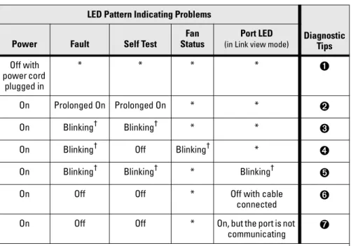
Diagnosing with the LEDs . . . 4-4
Proactive Networking . . . 4-8
Hardware Diagnostic Tests . . . 4-9 Testing the Switch by Resetting It . . . 4-9 Checking the Switch LEDs . . . 4-9 Checking Console Messages . . . 4-9 Testing Twisted-Pair Cabling . . . 4-10 Testing Switch-to-Device Network Communications . . . 4-10 Testing End-to-End Network Communications . . . 4-10
Restoring the Factory Default Configuration . . . 4-11
Downloading New Switch Software . . . 4-12
HP Customer Support Services . . . 4-12 Before Calling Support . . . 4-12
iii Electrical . . . A-1 Environmental . . . A-1 Acoustic . . . A-2 Connectors . . . A-2 Safety . . . A-2 Lasers . . . A-2
B Switch Ports and Network Cables
Switch Ports . . . B-1 Twisted-Pair Cables . . . B-1
Mode Conditioning Patch Cord for Gigabit-LX . . . B-3 Installing the Patch Cord . . . B-4 Recommended Patch Cords . . . B-4
Twisted-Pair Cable/Connector Pin-Outs . . . B-5 Straight-Through Twisted-Pair Cable for
10 Mbps or 100 Mbps Network Connections . . . B-7 Cable Diagram . . . B-7 Pin Assignments . . . B-7 Crossover Twisted-Pair Cable for
10 Mbps or 100 Mbps Network Connection . . . B-8 Cable Diagram . . . B-8 Pin Assignments . . . B-8 Straight-Through Twisted-Pair Cable for
1000 Mbps Network Connections . . . B-9 Cable Diagram . . . B-9 Pin Assignments . . . B-9
C Safety and EMC Regulatory Statements
Safety Information . . . C-1
EMC Regulatory Statements . . . C-8
1-1 In tr od uci n g th e HP P roc urve S w itc h 2650
Introducing the HP Procurve Switch 2650
The HP Procurve Switch 2650 is a multiport switch that can be used to build high-performance switched workgroup networks. This switch is a store-and-forward device that offers low latency for high-speed networking.
Throughout this manual, this switch will be abbreviated as the Switch 2650. The Switch 2650 has 48 auto-sensing 10/100Base-TX RJ-45 ports and two dual-personality ports—either auto-sensing 10/100/1000Base-T RJ-45 or mini-GBIC.
This switch is designed to be used primarily as a high-density wiring closet or desktop switch. With this switch you can directly connect computers, printers, and servers to provide dedicated bandwidth to those devices, and you can build a switched network infrastructure by connecting the switch to hubs, other switches, or routers. In addition, the Switch 2650 offers full network management capabilities.
This chapter describes your HP Switch 2650 including:
■ Front and back of the switch
■ Switch features Port LED View Self Test Clear Reset Fan Status 4 5 6 7 8 9 10 1112 1314 1516 1718 1920 2122 2324 2526 2728 2930 3132 3334 35363738 3940 4142 4344 4546 4748
Spd mode: off = 10 Mbps, flash = 100 Mbps, on = 1000 Mbps 10/100Base-TX Ports (1 - 48)
Gig-T Ports Mini-GBIC Ports 1 1517 1618 31 32 33 34 47 48 50 49 T M T M Power Fault hpprocurve switch 2650 J4899A
Use only one (T or M) for each Gigabit port
! 1 2 3 Spd Lnk Act FDx
In tr od uci ng th e HP P roc urve Switch 2650
Front of the Switch
Network Ports
■ 48 auto-sensing 10/100Base-TX ports.
All these ports have the “HP Auto MDIX” feature, which means that you can use either straight-through or crossover twisted-pair cables to connect any network devices to the switch.
■ Two dual-personality ports. You can use either the 10/100/1000Base-T
RJ-45 connector, or install a supported HP Procurve mini-GBIC for fiber-optic connections.
The RJ-45 connectors support the IEEE Auto MDI/MDI-X feature, which operates the same as the “HP Auto-MDIX” feature.
Dual-Personality Port Operation. By default, the RJ-45 connnectors are enabled. If a mini-GBIC is installed in a slot, it is enabled and the associated RJ-45 connector is disabled and cannot be used. If the mini-GBIC is removed, the associated RJ-45 port is automatically re-enabled.
Port LED View Self Test Clear Reset Fan Status 4 5 6 7 8 9 10 1112 1314 1516 1718 1920 2122 2324 2526 2728 2930 3132 3334 35363738 3940 4142 4344 45464748
Spd mode: off = 10 Mbps, flash = 100 Mbps, on = 1000 Mbps 10/100Base-TX Ports (1 - 48)
Gig-T Ports Mini-GBIC Ports 1 1517 1618 31 32 33 34 47 48 50 49 T M T M Power Fault hpprocurve switch 2650 J4899A
Use only one (T or M) for each Gigabit port
! 1 2 3 Spd Lnk Act FDx
Reset and Clear buttons
Port LED View select button and indicator LEDs
Switch port LEDs Self Test and Fan
Status LEDs Power and Fault LEDs HP Procurve Switch 2650 10/100Base-TX RJ-45 ports*
* All 10/100Base-TX RJ-45 ports have the HP Auto MDIX feature. 10/100/1000Base-T ports have the IEEE Auto MDI/MDI-X feature.
Dual-personality ports (1000Base-T* or mini-GBIC)
1-3 In tr od uci n g th e HP P roc urve S w itc h 2650
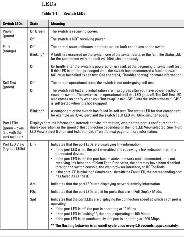
LEDs
Table 1-1. Switch LEDs
Switch LEDs State Meaning Power
(green)
On Green The switch is receiving power. Off The switch is NOT receiving power. Fault
(orange)
Off The normal state; indicates that there are no fault conditions on the switch.
Blinking* A fault has occurred on the switch, one of the switch ports, or the fan. The Status LED for the component with the fault will blink simultaneously.
On On briefly after the switch is powered on or reset, at the beginning of switch self test. If this LED is on for a prolonged time, the switch has encountered a fatal hardware failure, or has failed its self test. See chapter 4, “Troubleshooting” for more information. Self Test
(green)
Off The normal operational state; the switch is not undergoing self test.
On The switch self test and initialization are in progress after you have power cycled or reset the switch. The switch is not operational until this LED goes off. The Self Test LED also comes on briefly when you “hot swap” a mini-GBIC into the switch; the mini-GBIC is self tested when it is hot swapped.
Blinking* A component of the switch has failed its self test. The status LED for that component, for example an RJ-45 port, and the switch Fault LED will blink simultaneously. Port LEDs
(green – over-laid with the port number)
Displays port link information, network activity information, whether the port is configured for full-duplex operation, or the speed of the connection depending on the Port LED View selected. See “Port LED View Select Button and Indicator LEDs” on the next page for more information.
Port LED View (4 green LEDs)
Link Indicates that the port LEDs are displaying link information:
• if the port LED is on, the port is enabled and receiving a link indication from the connected device.
• if the port LED is off, the port has no active network cable connected, or is not receiving link beat or sufficient light. Otherwise, the port may have been disabled through the switch console, the web browser interface, or HP TopTools.
• if the port LED is blinking* simultaneously with the Fault LED, the corresponding port has failed its self test.
Act Indicates that the port LEDs are displaying network activity information. FDx Indicates that the port LEDs are lit for ports that are in Full Duplex Mode.
Spd Indicates that the port LEDs are displaying the connection speed at which each port is operating:
• if the port LED is off, the port is operating at 10 Mbps. • if the port LED is flashing**, the port is operating at 100 Mbps. • if the port LED is on continuously, the port is operating at 1000 Mbps.
In tr od uci ng th e HP P roc urve Switch 2650
Port LED View Select Button and Indicator LEDs
To optimize the amount of information that can be displayed for each of the switch ports without overwhelming you with LEDs, the Switch 2650 uses a single LED for each port. The operation of this LED is controlled by the Port LED View select button, and the current setting is indicated by the Port LED View indicator LEDs near the button. Press the button to step from one view mode to the next.
■ If the Link (Lnk) indicator LED is lit, each port LED displays link
infor-mation for the associated port.
If the port LED is in Link mode and it is blinking, the port has failed its self test. The Fault and Self Test LEDs will be blinking simultaneously.
■ If the Activity (Act) indicator LED is lit, each port LED displays activity
information for the associated port—it flickers as network traffic is received and transmitted through the port.
■ If the Full Duplex (FDx) indicator LED is lit, the port LEDs light for those
ports that are operating in full duplex. T/M
(green – ports 49 and 50 only)
On For the dual-personality ports, indicates the enabled port: • if the “T” is on, the 10/100/1000Base-T RJ-45 port is enabled. • if the “M” is on, the mini-GBIC port is enabled.
Fan Status (green)
On The cooling fan is operating normally.
Blinking* The cooling fan has failed. The switch Fault LED will be blinking simultaneously. * The blinking behavior is an on/off cycle once every 1.6 seconds, approximately.
Switch LEDs State Meaning
Port LED View Self Test Clear Reset Fan Status 4 5 6 7 8 9 10
Spd mode: off = 10 Mbps, flash = 100 Mbps, on = 1000 Mbps
1 Power Fault hpprocurve switch2650 J4899A 1 2 3 Spd Lnk Act FDx Port LED (one for each port)
Port LED View select button and indicator LEDs
1-5 In tr od uci n g th e HP P roc urve S w itc h 2650
■ If the Speed (Spd) indicator LED is lit, the port LEDs behave as follows
to indicate the connection speed for the port:
• Off = 10 Mbps
• Flashing = 100 Mbps (the flashing behavior is a repeated on/off cycle
once every 0.5 sec.)
• On = 1000 Mbps
Reset Button
This button is used to reset the switch while it is powered on. This action clears any temporary error conditions that may have occurred and executes the switch self test.
Clear Button
This button is used for these purposes:
■ Deleting Passwords - When pressed by itself for at least one second, the button deletes any switch console access passwords that you may have configured. Use this feature if you have misplaced the password and need console access.
This button is provided for your convenience, but its presence means that if you are concerned with the security of the switch configuration and operation, you should make sure the switch is installed in a secure location, such as a locked wiring closet.
■ Restoring Factory Default Configuration - When pressed with the Reset button in a specific pattern, any configuration changes you may have made through the switch console, the web browser interface, and SNMP management are removed, and the factory default configuration is restored to the switch. For the specific method to restore the factory default configuration, see “Restoring the Factory Default Configuration” in chapter 4, “Troubleshooting” of this manual.
In tr od uci ng th e HP P roc urve Switch 2650
Back of the Switch
Console Port
This port is used to connect a console to the Switch 2650 by using the serial cable supplied with the switch. This connection is described under “Connect a Console to the Switch” in chapter 2, “Installing the Switch”. The console can be a PC or workstation running a VT-100 terminal emulator, or a VT-100 terminal.
Power Connector
The Switch 2650 does not have a power switch; it is powered on when connected to an active AC power source. The switch automatically adjusts to any voltage between 100--240 volts and either 50 or 60 Hz. There are no voltage range settings required.
Console
AC power connector Cooling vent - make sure this is not
obstructed for proper switch operation
1-7 In tr od uci n g th e HP P roc urve S w itc h 2650
Switch Features
The features of the Switch 2650 include:
■ 48 auto-sensing 10/100Base-TX RJ-45 ports with HP Auto-MDIX.
■ two dual-personality ports—either the auto sensing 10/100/1000Base-T
RJ-45 or the mini-GBIC can be used for each port.
■ plug-and-play networking—all ports are enabled—just connect the
network cables to active network devices and your switched network is operational.
■ HP Auto-MDIX on all 10/100 twisted-pair ports, and IEEE 802.3ab Auto
MDI /MDI-X on all 10/100/1000 twisted-pair ports, meaning that all
connections can be made using straight-through twisted-pair cables. Cross-over cables are not required, although they will also work. The pin operation of each port is automatically adjusted for the attached device: if the switch detects that another switch or hub is connected to the port, it configures the port as MDI; if the switch detects that an end-node device is connected to the port, it configures the port as MDI-X.
■ automatic learning of the network addresses in each switch’s
8000-address forwarding table, (with configurable 8000-address aging value).
■ automatically negotiated full-duplex operation for the 10/100 and
10/100/1000 RJ-45 ports when connected to other auto-negotiating devices—the mini-GBIC ports always operate at full duplex.
■ easy management of the switch through several available interfaces:
• console interface—a full featured, easy to use, VT-100 terminal interface that is especially good for out-of-band switch management or for Telnet access to the switch.
• web browser interface—an easy to use built-in graphical interface that can be accessed from common web browsers.
• HP TopTools for Hubs & Switches—an SNMP-based, graphical network management tool that you can use to manage your entire network. This product is included with your new switch.
■ support for the Spanning Tree Protocol to eliminate network loops
■ support for up to 30 IEEE 802.1Q-compliant VLANs so you can divide the
attached end nodes into logical groupings that fit your business needs.
■ support for many advanced features to enhance network performance—
for a description, see the Management and Configuration Guide, which
is on the Documentation CD-ROM that is included with your switch.
2-1 In sta llin g th e Switc h 2650
Installing the Switch 2650
The HP Switch 2650 is easy to install. It comes with an accessory kit that includes the brackets for mounting the switch in a standard 19-inch telco rack, in an equipment cabinet, or on a wall, and with rubber feet that can be attached so the switch can be securely located on a horizontal surface. The brackets are designed to allow mounting the switch in a variety of locations and orientations.
This chapter shows you how to install your Switch 2650.
Included Parts
The Switch 2650 has the following components shipped with it:
■ HP Procurve Switch 2650 Installation and Getting Started Guide
(J4899-90001), this manual
■ HP Procurve Product Documentation CD ROM
(contains PDF file copies of the documentation for the Switch 2650,
including the Management and Configuration Guide, and for most other
HP Procurve switches)
■ HP TopTools for Hubs & Switches - CD ROM and booklet
■ Console cable
■ Customer Support/Warranty booklet
■ Accessory kit (5064-2085)
• two mounting brackets
• four 8-mm M4 screws to attach the mounting brackets to the switch
• four 5/8-inch number 12-24 screws to attach the switch to a rack
• four rubber feet
■ Power cord, one of the following:
Australia/New Zealand China Continental Europe Denmark Japan Switzerland
United Kingdom/Hong Kong/Singapore United States/Canada/Mexico 8120-6803 8120-8377 8120-6802 8120-6806 8120-6804 8120-6807 8120-8709 8120-6805
In sta llin g th e Switc h 2650
Installation Procedures
Summary
Follow these easy steps to install your switch. The rest of this chapter provides details on these steps.
1. Prepare the installation site (page 2-4). Make sure that the physical environment into which you will be installing the switch is properly prepared, including having the correct network cabling ready to connect
to the switch and having an appropriate location for the switch. Please see
page 2-3 for some installation precautions.
2. Install mini-GBICs (optional—page 2-6). The switch has two slots for installing mini-GBICs. Depending on where you will install the switch, it may be easier to install the mini-GBICs first. Note that the mini-GBICs can be hot swapped—they can be installed or removed while the switch is powered on.
3. Verify that the switch passes self test (page 2-8). This is a simple process of plugging the switch into a power source and observing that the LEDs on the switch’s front panel indicate correct switch operation. 4. Mount the switch (page 2-10). The Switch 2650 can be mounted in a
19-inch telco rack, in an equipment cabinet, on a wall, or on a horizontal surface.
5. Connect power to the switch (page 2-15). Once the switch is mounted, plug it into the nearby main power source.
6. Connect the network devices (page 2-16). Using the appropriate network cables, connect the network devices to the switch ports. 7. Connect a console to the switch (optional—page 2-17). You may
wish to modify the switch’s configuration, for example, to configure an IP address so it can be managed using a web browser, from an SNMP network management station, or through a Telnet session. Configuration changes can be made easily by using the included console cable to connect a PC to the switch’s console port.
At this point, your switch is fully installed. See the rest of this chapter if you need more detailed information on any of these installation steps.
2-3 In sta llin g th e Switc h 2650
Installation Precautions:
Follow these precautions when installing your HP Switch 2650.
W a r n i n g
■ The rack or cabinet should be adequately secured to prevent it frombecoming unstable and/or falling over.
Devices installed in a rack or cabinet should be mounted as low as possible, with the heaviest devices at the bottom and progressively lighter devices installed above.
■ For safe operation, do not install the switch with the back face of the
switch (with the fan vents) facing either downward or upward.
C a u t i o n s
■ Make sure that the power source circuits are properly grounded, then usethe power cord supplied with the switch to connect it to the power source.
■ If your installation requires a different power cord than the one supplied
with the switch, be sure to use a power cord displaying the mark of the safety agency that defines the regulations for power cords in your country. The mark is your assurance that the power cord can be used safely with the switch.
■ When installing the switch, note that the AC outlet should be near the
switch and should be easily accessible in case the switch must be powered off.
■ Ensure that the switch does not overload the power circuits, wiring, and
over-current protection. To determine the possibility of overloading the supply circuits, add together the ampere ratings of all devices installed on the same circuit as the switch and compare the total with the rating limit for the circuit. The maximum ampere ratings are usually printed on the devices near the AC power connectors.
■ Do not install the switch in an environment where the operating ambient
temperature might exceed 55°C (131°F).
■ Make sure the air flow around the sides and back of the switch is not
In sta llin g th e Switc h 2650
1. Prepare the Installation Site
■ Cabling Infrastructure - Ensure that the cabling infrastructure meets the necessary network specifications. See the following table for cable types and lengths, and see appendix B, “Cables and Connectors” for more information:
Table 2-1. Summary of Cable Types to Use With the Switch
Port Type Cable Type Length Limits Twisted-Pair Cables
10/100Base-TX • 10 Mbps operation:
Category 3, 4, or 5, 100-ohm unshielded twisted-pair (UTP)
• 100 Mbps operation:
Category 5, 100-ohm UTP or shielded twisted-pair (STP) cable.
100 meters
Note: Since the 10Base-T operation is through 10/100Base-TX ports, if you ever want to upgrade the ports to 100Base-TX, it would be best to cable the ports initially with category 5 cable.
The 10/100-Base-TX ports on the Switch 2650 include the “HP Auto-MDIX” feature, which allows you to use either straight-through or crossover twisted-pair cables for connecting to any network devices including end nodes, such as computers, or to other switches, hubs, and routers.
10/100/1000Base-T For either 10, 100 Mbps, or 1000 Mbps operation:
Category 5 or better, 100-ohm UTP or shielded twisted-pair (STP) balanced cable. For 1000 Mbps (gigabit) operation, Category 5E cabling or better is recommended.
Note: For 1000 Mbps operation, all four wire pairs are used for data transmission.
100 meters
Note: The Switch 2650 is compatible with the IEEE 802.3ab standard including the “Auto MDI/MDI-X” feature, which allows you to use either straight-through or crossover twisted-pair cables for connecting to any network devices including end nodes, such as computers, or to other switches, hubs, and routers.
2-5 In sta llin g th e Switc h 2650
■ Installation Location - Before installing the switch, plan its location and orientation relative to other devices and equipment:
• In the front of the switch, leave at least 7.6 cm (3 inches) of space for
the twisted-pair and fiber-optic cabling.
• In the back of the switch, leave at least 3.8 cm (1 1/2 inches) of space
for the power cord.
• On the sides of the switch, leave at least 7.6 cm (3 inches) for cooling,
except if the switch is installed in an open EIA/TIA rack.
Fiber Optic Cables Gigabit-SX
(on Gigabit-SX-LC mini-GBIC)
62.5/125 µm or 50/125 µm core/cladding diameter, graded-index, multimode fiber-optic cables that are fitted with LC connectors
• 62.5 µm cable: – 160 MHz*km = 220 meters – 200 MHz*km = 275 meters • 50 µm cable: – 400 MHz*km = 500 meters – 500 MHz*km = 550 meters Gigabit-LX (on Gigabit-LX-LC mini-GBIC)
Single-mode cables fitted with LC connectors. 62.5/125 µm or 50/125 µm core/cladding diameter, graded-index, multimode fiber-optic cables may also be used, but a mode conditioning patch cord may be needed — see “Mode Conditioning Patch Cord for Gigabit-LX” on page B-3 for more information.
• single-mode cable = 5 kilometers • multimode cable = 550 meters
Gigabit-LH (on Gigabit-LH-LC mini-GBIC)
Single-mode cables fitted with LC connectors. • single-mode cable = 70 kilometers Port Type Cable Type Length Limits
In sta llin g th e Switc h 2650
2. Installing or Removing mini-GBICs
You can install or remove a mini-GBIC from a mini-GBIC slot without having to power off the switch. Use only HP Procurve mini-GBICs.
N o t e s
■ The mini-GBIC slots are shared with the two 10/100/1000Base-T RJ-45ports. If a mini-GBIC is installed in a slot, the associated RJ-45 port is disabled and cannot be used.
■ The mini-GBIC ports operate only at full duplex. Half duplex operation is
not supported.
■ Make sure that the network cable is NOT connected when you install or
remove a mini-GBIC.
When this manual was printed, the supported mini-GBICs include the following:
■ HP Procurve Gigabit-SX-LC mini-GBIC (J4858A)
■ HP Procurve Gigabit-LX-LC mini-GBIC (J4859A)
■ HP Procurve Gigabit-LH-LC mini-GBIC (J4860A)
C a u t i o n
The HP Procurve mini-GBICs are Class 1 laser devices. Avoid direct eyeexposure to the beam coming from the transmit port.
Installing the mini-GBICs:
Hold the mini-GBIC by its sides and gently insert it into either of the slots on the switch until the mini-GBIC clicks into place.
48 47 46 45 43 44 42 41 40 39 38 37 Gig-T Ports Mi ni-GBIC Ports 47 48 50 49 T M T M Useonl y one(T or M)for each G igabit port !
2-7 In sta llin g th e Switc h 2650
Removing the mini-GBICs:
N o t e
You should disconnect the network cable from the mini-GBIC before removingit from the switch.
Depending on when you purchased your HP Procurve mini-GBIC, it may have either of three different release mechanisms: a plastic tab on the bottom of the mini-GBIC, a plastic collar around the mini-GBIC, or a wire bail.
To remove the mini-GBICs that have the plastic or plastic collar, push the tab or collar toward the switch until you see the mini-GBIC release from the switch (you can see it move outward slightly), and then pull it from the slot.
To remove the mini-GBICs that have the wire bail, lower the bail until it is approximately horizontal, and then using the bail, pull the mini-GBIC from the slot.
In sta llin g th e Switc h 2650
3. Verify the Switch Passes Self Test
Before mounting the switch in its network location, you should first verify that it is working properly by plugging it into a power source and verifying that it passes its self test.
1. Connect the power cord supplied with the switch to the power connector
on the back of the switch, and then into a properly grounded electrical outlet.
N o t e
The Switch 2650 does not have a power switch. It is powered on when thepower cord is connected to the switch and to a power source. For safety, the power outlet should be located near the switch installation.
The switch automatically adjusts to any voltage between 100-240 volts and either 50 or 60 Hz. There are no voltage range settings required.
If your installation requires a different power cord than the one supplied with the switch, be sure to use a power cord displaying the mark of the safety agency that defines the regulations for power cords in your country. The mark is your assurance that the power cord can be used safely with the switch.
Console
Connect power cord to the power connector
2-9 In sta llin g th e Switc h 2650
2. Check the LEDs on the switch as described below.
When the switch is powered on, it performs its diagnostic self test. Self test takes approximately 50 seconds to complete.
LED Behavior:
During the self test:
• Initially, all the switch and port LEDs are on and stay on for most of
the duration of the self test.
• Most of the LEDs go off and then may come on again during phases
of the self test. For the duration of the self test, the Self Test LED stays on.
When the self test completes successfully:
• The Power and Fan Status LEDs remain on.
• The Fault and Self Test LEDs go off.
• The port LEDs on the front of the switch go into their normal
opera-tional mode:
– If the ports are connected to active network devices, the LEDs
behave according to the Port LED View selected. In the default view mode (Link), the LEDs should be on.
– If the ports are not connected to active network devices, the LEDs
will stay off.
If the LED display is different than what is described above, especially if the Fault and Self Test LEDs stay on for more than 60 seconds or they start blinking, the self test has not completed correctly. Refer to chapter 4, “Troubleshooting” for diagnostic help.
Port LED View Self Test Clear Reset Fan Status 4 5 6 7 8 9 10 11 12 13 14 15 16 17 18 19 20 21 22 23 24
Spd mode: off = 10 Mbps, flash = 100 Mbps, on = 1000 Mbps 10/100Base-TX P
1 1517 16 18 Power Fault hpprocurve switch 2650 J4899A 1 2 3 Spd Lnk Act FDx
Self Test LED Switch port LEDs
Power and Fault LEDs
In sta llin g th e Switc h 2650
4. Mount the Switch
After you have verified that the switch passes self test, you are ready to mount the switch in a stable location. The Switch 2650 can be mounted in these ways:
■ in a rack or cabinet
■ on a horizontal surface
■ on a wall
Rack or Cabinet Mounting
The Switch 2650 is designed to be mounted in any EIA-standard 19-inch telco rack or communication equipment cabinet. Note that the mounting brackets have multiple mounting holes and can be rotated allowing for a wide variety of mounting options.
W a r n i n g
For safe operation, please read the mounting precautions onpage 2-3, before mounting a switch.
E q u i p m e n t
C a b i n e t
N o t e
The 12-24 screws supplied with the switch are the correct threading for standard EIA/TIA open 19-inch racks. If you are installing the switch in an equipment cabinet such as a server cabinet, use the clips and screws that came with the cabinet in place of the 12-24 screws that are supplied with the switch. Complete step 1, on the next page. Then, plan which four holes you will be using in the cabinet and install all four clips and partially install the two bottom screws, as described in step 2 on the following page. Then proceed to step 3.
2-11 In sta llin g th e Switc h 2650
1. Use a #1 Phillips (cross-head) screwdriver and attach the mounting
brackets to the switch with the included 8-mm M4 screws.
N o t e
Note that the mounting brackets have multiple mounting holes and can berotated allowing for a wide variety of mounting options. These include mounting the switch so that its front face is flush with the face of the rack, or mounting it in a more balanced position as shown in the illustration.
N o t e
Steps 2, 3, and 4 on the next page describe a convenient method of mountingthe switch in a rack by placing it on two screws that you first install in the rack. You may, instead, just hold the switch with attached brackets up to the rack and move it vertically until rack holes line up with the bracket holes and notches, then insert and tighten the four screws holding the brackets to the rack.
8 mm M4 screws
In sta llin g th e Switc h 2650
2. Partially install a screw (5/8-inch number 12-24) into the top hole of a pair
of holes that are 0.5 inches apart in each rack/cabinet upright as shown in the illustration below. Ensure that the screws are at the same level in each upright.
3. Place the switch in the rack and lower it so the notches in the bottom of
the bracket slide onto the screws, then tighten these screws. Partially install a screw
into the top hole of a close (0.5-inch) pair on
both sides of the rack
Lower switch with mounting brackets onto the partially
2-13 In sta llin g th e Switc h 2650
4. Install the other number 12-24 screw into the upper hole in each bracket.
Tighten these screws.
Wall Mounting
You can mount the switch on a wall as shown in the illustrations on the next page.
W a r n i n g
For safe operation, do not install the switch with the back face of theswitch (with the fan vents) facing either downward or upward.
C a u t i o n
The switch should be mounted only to a wall or wood surface that is at least1/2-inch plywood or its equivalent.
1. Use a #1 Phillips (cross-head) screwdriver and attach the mounting
brackets to the switch with the included 8-mm M4 screws.
2. Attach the switch to the wall or wood surface with two 5/8-inch number
12 wood screws (not included). Install additional
In sta llin g th e Switc h 2650
For “Bookshelf” Wall Mounting For “Flat” Wall Mounting
5/8-inch wood screw
Second 5/8-inch wood screw (hidden)
M4 screws
5/8-inch wood screws
M4 screws
Note that the brackets are attached on opposite corners. This improves the stability of the switch on the wall.
2-15 In sta llin g th e Switc h 2650
Horizontal Surface Mounting
Place the switch on a table or other horizontal surface. The switch comes with rubber feet in the accessory kit that can be used to help keep the switch from sliding on the surface.
Attach the rubber feet to the four corners on the bottom of the switch within the embossed angled lines. Use a sturdy surface in an uncluttered area. You may want to secure the networking cables and switch power cord to the table leg or other part of the surface structure to help prevent tripping over the cords.
C a u t i o n
Make sure the air flow is not restricted around the sides and back of the switch.5. Connect the Switch to a Power Source
1. Plug the included power cord into the switch’s power connector and into
a nearby AC power source.
In sta llin g th e Switc h 2650
6. Connect the Network Cables
Connect the network cables, described under “Cabling Infrastructure” (page 2-4), from the network devices or your patch panels to the fixed RJ-45 ports on the switch or to any mini-GBICs you have installed in the switch.
Using the RJ-45 Connectors
To connect:
Push the RJ-45 plug into the RJ-45 jack until the tab on the plug clicks into place. When power is on for the switch and for the connected device, the Link LED for the port should light to confirm a powered-on device (for example, an end node) is at the other end of the cable.
If the Link LED does not go on when
the network cable is connected to the port, see “Diagnosing With the LEDs” in chapter 4, “Troubleshooting”.
To disconnect:
Press the small tab on the plug and
pull the plug out of the jack.
Connecting Cables to mini-GBICs
N o t e
The mini-GBIC slots are shared with the two 10/100/1000Base-T RJ-45 ports.If a mini-GBIC is installed in a slot, the associated RJ-45 port is disabled. If you have any mini-GBICs installed in the switch, the type of network connections you will need to use depends on the type of mini-GBICs you have installed. See the table on page 2-5, and appendix B, “Switch Ports and Network Cables”, for the mini-GBIC cabling information.
For mini-GBICs ports, and in general for all the switch ports, when a network cable from an active network device is connected to the port, the port LED
for that port should go on. If the port LED does not go on when the network
cable is connected to the port, see “Diagnosing With the LEDs” in chapter 4, Port LED View Self Test Clear eset Fan Status 4 5 6
Spd mode: off = 10 Mbps, flash = 1 hpprocurve switch2650 J4899A 1 2 3 Spd Lnk Act FDx RJ-45 connector
Unshielded twisted-pair cable: • Category 3, 4, or 5 for 10 Mbps ports • Category 5 or better for 100 Mbps ports • Category 5E or better for 1000 Mbps ports Maximum distance: 100 meters
2-17 In sta llin g th e Switc h 2650
7. (Optional) Connect a Console to the Switch 2650
The Switch 2650 has a full-featured, easy to use console interface for performing switch management tasks including the following:
■ Monitor switch and port status and observe network activity statistics
■ Modify the switch’s configuration to optimize switch performance,
enhance network traffic control, and improve network security
■ Read the event log and access diagnostic tools to help in troubleshooting
■ Download new software to the switch
■ Add passwords to control access to the switch from the console, web
browser interface, and network management stations The console can be accessed through these methods:
■ Out-of-band: The Switch 2650 comes with a serial cable for connecting a PC or VT-100 terminal, to be used as a console, directly to the switch.
■ In-Band: Access the console using Telnet from a PC or UNIX station on the network, and a VT-100 terminal emulator. This method requires that you first configure the switch with an IP address and subnet mask by using either out-of-band console access or through DHCP/Bootp. For more information on IP addressing and on starting a Telnet session, see
chapter 3, “Getting Started With Switch Configuration”, and the
Manage-ment and Configuration Guide, which is on the Documentation CD-ROM
that came with your switch.
The Switch 2650 can simultaneously support one out-of-band console session through the Console Port and one in-band Telnet console session.
Terminal Configuration
To connect a console to the switch, configure the PC terminal emulator as a DEC VT-100 (ANSI) terminal or use a VT-100 terminal, and configure either one to operate with these settings:
• any baud rate from 1200 to 115200 (the switch senses the speed)
• 8 data bits, 1 stop bit, no parity, and flow control set to Xon/Xoff
• For the Windows Terminal program, also disable (uncheck) the “Use
Function, Arrow, and Ctrl Keys for Windows” option
• For the Hilgraeve HyperTerminal program, select the “Terminal keys”
option for the “Function, arrow, and ctrl keys act as” parameter. If you want to operate the console using a different configuration, make sure you change the settings on both the terminal and on the switch so they are compatible. Change the switch settings first, then change the terminal settings, then reboot the switch and reestablish the console session.
In sta llin g th e Switc h 2650
Direct Console Access
To connect a console to the switch, follow these steps:1. Connect the PC or
terminal to the switch’s Console Port using the console cable included with the Switch 2650. (If your PC or terminal has a 25-pin serial connector, first attach a 9-pin to 25-pin straight-through adapter at one end of the console cable.)
2. Turn on the terminal or
PC’s power and, if using a PC, start the PC terminal program.
3. Press[Enter] two or three times and you will see the copyright page and the
message “Press any key to continue”. Press a key, and you will then see the switch console command (CLI) prompt, for example:
HP Procurve Switch 2650#
If you want to continue with console management of the switch at this time, see chapter 3, “Getting Started With Switch Configuration” for some basic
configuration steps. For more detailed information, refer to the Management
and Configuration Guide, which is on the Documentation CD-ROM that came
with your switch.
Console
Console port
Console cable supplied with the switch
PC running a terminal emulator program, or a VT-100 terminal
2-19 In sta llin g th e Switc h 2650
Sample Network Topologies
This section shows you a few sample network topologies in which the Switch 2650 is implemented. For more topology information, see the HP
network products World Wide Web site, http://www.hp.com/go/hpprocurve.
As a Desktop Switch
The Switch 2650 is designed to be used primarily as a desktop switch to which end nodes, printers and other peripherals, and servers are directly connected, as shown in the above illustration. Notice that the end node devices are connected to the switch by “straight-through” or “crossover” twisted-pair cables. Either cable type can be used because of the “HP Auto-MDIX” and “IEEE Auto MDI/MDI-X” features on the Switch 2650.
PortLEDView SelfTest Clear Reset FanStatus 45 48 47 46 45 4344 42 41 40 39 38 37 36 35 34 33 32 31 30 29 28 27 26 25 24 23 22 21 20 19 18 17 16 15 14 13 12 11 10 9 87 6 Spd mode:off =10 Mbps, flash= 100Mbps,on =1000Mbps 10/100Base-TXPorts(1 - 48) Gig-TPorts Mini-GBICPorts 1 1517 1618 31 32 33 34 47 48 50 49 TMTM Power Fault hpprocurve switch 2650 J4899A
Use only one (Tor M) foreachGigabitport
! 123 Spd LnkActFDx Twisted-pair “straight-through” or “crossover” cables Switch 2650 PCs and peripherals Server
In sta llin g th e Switc h 2650
As a Segment Switch
The Switch 2650 also works well as a segment switch. That is, with its high performance, it can be used for interconnecting network segments—simply connect the network hubs that form those segments to the switch, or you can also connect other switches.
In the illustration above, two “Fast” Ethernet hubs with PCs, printers, and local servers attached, are both connected to a Switch 2650. The devices attached to the two hubs can now communicate with each other through the switch. They can also all communicate with the server that is connected to a 1000Base-T port on the switch.
Because the Switch 2650 has the “HP Auto-MDIX” and “IEEE Auto MDI/ MDI-X” features, the connections between the switch and the hubs, and between the switch and end nodes or servers can be through category 5 “straight-through” or “crossover” twisted-pair cable. Category 3 or 4 cable can also be used if the connection is 10 Mbps only. In all cases, the device ports must be configured to auto negotiate the link characteristics for this feature to work.
The switch, in turn, can be connected to a network backbone through fiber-optic cabling connected to a Gigabit-SX, -LX, or -LH mini-GBIC installed in the switch. Now, all the devices on these network segments can access other network resources that are connected elsewhere on the network backbone.
PortLEDView SelfTest Clear Reset FanStatus 45 48 47 46 45 4344 42 41 40 39 38 37 36 35 34 33 32 31 30 29 28 27 26 25 24 23 22 21 20 19 18 17 16 15 14 13 12 11 10 9 87 6
Spd mode:off =10 Mbps,flash= 100Mbps,on =1000Mbps 10/100Base-TXPorts(1 - 48) Gig-TPorts Mini-GBICPorts 1 1517 1618 31 32 33 34 47 48 50 49 TMTM Power Fault hpprocurve switch 2650 J4899A
Use only one (T or M)for each Gigabitport
! 123 Spd LnkActFDx Printers Printers “Fast” Ethernet Hubs PCs, printers, and local servers Switch 2650 Server with “Gigabit” Ethernet NIC Twisted-pair “straight-through” cables to end nodes Twisted-pair “straight-through” or “crossover” cables to hubs Category 5E twisted-pair “straight-through” or “crossover” cable for 1000 Mbps connection to server
Gigabit fiber-optic cable
2-21 In sta llin g th e Switc h 2650
Connecting to a Backbone Switch
The simpler desktop and segment networks shown in the previous two examples can easily be combined and expanded. For example, you could use an HP Procurve Switch 8000M to interconnect each of your smaller switched workgroups to form a larger switched network. All the devices in this network can communicate with each other. With a Gigabit-SX Module, for example, in the Switch 8000M, the entire switched topology could be connected to a campus backbone, as shown in the illustration above.
N o t e
In the illustration above, the 1000 Mbps fiber-optic connection between theSwitch 2650 and the Switch 8000M is by way of a Gigabit-SX mini-GBIC installed in the Switch 2650 connected to a Gigabit-SX Module in the Switch 8000M. PortLEDView SelfTest Clear Reset FanStatus 45 48 47 46 45 4344 42 41 40 39 38 37 36 35 34 33 32 31 30 29 28 27 26 25 24 23 22 21 20 19 18 17 16 15 14 13 12 11 10 98 7 6
Spd mode:off =10 Mbps,flash= 100Mbps,on =1000Mbps 10/100Base-TXPorts(1 - 48) Gig-TPorts Mini-GBICPorts 1 1517 1618 31 32 33 34 47 48 50 49 T MTM Power Fault hpprocurve switch 2650 J4899A
Use only one (Tor M)for each Gigabitport
! 123 Spd LnkActFDx PortLEDView SelfTest Clear Reset FanStatus 45 48 47 46 45 4344 42 41 40 39 38 37 36 35 34 33 32 31 30 29 28 27 26 25 24 23 22 21 20 19 18 17 16 15 14 13 12 11 10 9 87 6
Spd mode:off =10 Mbps,flash= 100Mbps,on =1000Mbps 10/100Base-TXPorts(1 - 48) Gig-TPorts Mini-GBICPorts 1 1517 1618 31 32 33 34 47 48 50 49 TMTM Power Fault hpprocurve switch 2650 J4899A
Use only one (T or M)for each Gigabit port
! 123 Spd LnkActFDx Printers Printers Console Fault Power HP J4110A ProCurve Switch 8000M Reset Clear
Switch Engine Module Mode Select
ActFdx 100
Switch Engine FailSelf Test
A HP Switch Gigabit-SX Module Tx LinkMode Rx A HP Switch 10Base-FL Module Tx Tx LinkMode Tx Tx Rx Rx Rx Rx 2 1 3 4 A 1X Link HP Switch 10/100Base-T Module Mode 2X 3X 4X 5X 7X 6X 8X A 1X Link HP Switch 10/100Base-T Module Mode 2X 3X 4X 5X 7X 6X 8X A 1X Link HP Switch 10/100Base-T Module Mode 2X 3X 4X 5X 7X 6X 8X A 1X Link HP Switch 10/100Base-T Module Mode 2X 3X 4X 5X 7X 6X 8X A A B D E F G H I J StatusA I E C 1 G B J F D 2 H Modules Power Fan C A HP Switch Gigabit-SX Module Tx Link Mode Rx A HP Switch Gigabit-SX Module Tx LinkMode Rx Switch 2650 Switch 2650 Switch 8000M To Gigabit-Ethernet backbone Gigabit fiber-optic cable
In sta llin g th e Switc h 2650
Stacking the Switch
Switch 2650 units can be connected together, through standard network connections, and managed through a single IP address. Up to 16 switches can be connected together in such a “virtual stack”.
You identify the switch as the “Commander” and give that switch an IP address. Up to 15 other switches in the network can then easily be configured as Members of the stack and managed through the Commander’s IP address. The management includes Telnet access and web browser interface access to the Commander and to each Member switch through the Commander.
For more information on stacking your Switch 2650, please see the
Manage-ment and Configuration Guide, which is on the Documentation CD-ROM that
3-1 Ge tti n g S ta rte d With Sw itc h Co n fig u ra tio n
Getting Started With Switch Configuration
This chapter is a guide for using the console Switch Setup screen to quickly assign an IP (Internet Protocol) address and subnet mask to the switch, set a Manager password, and, optionally, configure other basic features.
For more information on using the switch console and the other switch management interfaces: the web browser interface and the SNMP
manage-ment tool, HP TopTools for Hubs & Switches, please see the Management and
Configuration Guide, which is on the Documentation CD-ROM that came
with your switch.
Recommended Minimal Configuration
In the factory default configuration, the switch has no IP (Internet Protocol) address and subnet mask, and no passwords. In this state, it can be managed only through a direct console connection. To manage the switch through in-band (networked) access, you should configure the switch with an IP address and subnet mask compatible with your network. Also, you should configure a Manager password to control access privileges from the console and web browser interface. Other parameters in the Switch Setup screen can be left at their default settings or you can configure them with values you enter. Many other features can be configured through the switch’s console interface, to optimize the switch’s performance, to enhance your control of the network traffic, and to improve network security. Once an IP address has been config-ured on the switch, these features can be accessed more conveniently through a remote Telnet session, through the switch’s web browser interface, and from an SNMP network management station running a network management program, such as HP TopTools for Hubs & Switches. For a listing of switch features available with and without an IP address, refer to “How IP Addressing
Affects Switch Operation” in the Management and Configuration Guide,
which is on the Documentation CD-ROM that came with your switch. For more information on IP addressing, refer to “IP Configuration” in the
G e tti n g St a rte d With Sw itc h Co nf ig u rat io n
N o t e
By default, the switch is configured to acquire an IP address configurationfrom a DHCP or Bootp server. To use DHCP/Bootp instead of the manual method described in this chapter, see “DHCP/Bootp Operation” in the
Management and Configuration Guide, which is on the Documentation
CD-ROM that came with your switch.
Using the Console Setup Screen
The quickest and easiest way to minimally configure the switch for manage-ment and password protection in your network is to use a direct console connection to the switch, start a console session, and access the Switch Setup screen.
1. Using the method described in the preceding section, connect a terminal
device to the switch and display the switch console command (CLI) prompt (the default display).
The CLI prompt appears displaying the switch model number: HP Procurve Switch 2650#
2. At the prompt, enter the setup command to display the Switch Setup
screen. The following illustration shows the Setup screen with the default settings.
3. Use the [Tab] key to select the Manager Password field and enter a manager
3-3 Ge tti n g S ta rte d With Sw itc h Co n fig u ra tio n
4. [Tab] to the IP Config (DHCP/Bootp) field and use the Space bar to select the Manual option.
5. [Tab] to the IP Address field and enter the IP address that is compatible with your network.
6. [Tab] to the Subnet Mask field and enter the subnet mask used for your network.
7. Press [Enter], then [S] (for Save).
Here is some information on the fields in the Setup screen. For more
informa-tion on these fields, see the Management and Configuration Guide, which is
on the Documentation CD-ROM that came with your switch:
Parameter Default
System Name blank Optional; up to 25 characters, including spaces System Contact blank Optional; up to 48 characters, including spaces Manager Password blank Recommended; up to 16 characters (no blank spaces)
Logon Default CLI The default setting selects the command line interface for console access. The alternative is the menu interface.
Time Zone 0 (none) Optional; 1440 to -1440. The number of minutes your location is to the West (-) or East (+) of GMT.
Community Name public Default setting recommended.
Spanning Tree Enabled No Default setting recommended unless STP is already running on your network or the switch will be used in complex network topologies.
Default Gateway blank Optional; Enter the IP address of the next-hop gateway node if network traffic needs to be able to reach off-subnet destinations.
Time Sync Method None Optional; The protocol the switch uses to acquire a time signal. The options are SNTP and TimeP.
TimeP Mode Disabled Optional; The method the switch uses to acquire the TimeP server address. IP Config (DHCP/Bootp) DHCP/Bootp Set to Manual unless a DHCP/Bootp server is used on your network to
configure IP addressing.
IP Address xxx.xxx.xxx.xxx Recommended; If you set IP Config to Manual, then enter an IP address compatible with your network.
Note: The IP address and subnet mask assigned for the switch must be compatible with the IP addressing used in your network. For more information on IP addressing, see the Management and Configuration Guide, which is on the Documentation CD-ROMthat came with your switch.
Subnet Mask xxx.xxx.xxx.xxx Recommended; If you entered an IP address, then enter a subnet mask compatible with your network.
G e tti n g St a rte d With Sw itc h Co nf ig u rat io n
Where to Go From Here
The above procedure configures your switch with a Manager password, IP address, and subnet mask. As a result, with the proper network connections, you can now manage the switch from a PC equipped with Telnet, a web browser interface, or from an SNMP-based network management station using a tool such as HP TopTools for Hubs & Switches.
Some basic information on managing your switch is included in the next section. For more information on the console, web browser, and SNMP management interfaces and all the features that can be configured on the
Switch 2650, please see the Management and Configuration Guide, which is
on the Documentation CD-ROM that came with your switch.
To Recover from a Lost Manager Password: If you cannot start a con-sole session at the manager level because of a lost Manager password, you can clear all passwords and user names by getting physical access to the switch and pressing and holding the Clear button for a full second.
3-5 Ge tti n g S ta rte d With Sw itc h Co n fig u ra tio n
Using the IP Address for Remote Switch
Management
With your Switch 2650, you can use the switch’s IP address to manage the switch from any PC that is on the same subnet as the switch. You can use either a Telnet session or a standard web browser to manage the switch.
Starting a Telnet Session
To access the switch through a Telnet session, follow these steps:
1. Make sure the switch is configured with an IP address and that the switch
is reachable from the PC that is running the Telnet session (for example, by using a Ping command to the switch’s IP address).
2. Start the Telnet program on a PC that is on the same subnet as the switch
and connect to the switch’s IP address.
3. You will see the copyright page and the message “Press any key to
continue”. Press a key, and you will then see the switch console command (CLI) prompt, for example:
HP Procurve Switch 2650#
Enter help or ? to see a list of commands that can be executed at the prompt. Entering any command followed by help provides more detailed context help information about the command. Entering any command followed by ? displays a list of options that are available at that point in the command entry.
Starting a Web Browser Session
Your Switch 2650 can be managed through a graphical interface that you can access from any PC or workstation on the network by running your web browser and typing in the switch’s IP address as the URL. No additional software installation is required to make this interface available; it is included in the switch’s onboard software.
G e tti n g St a rte d With Sw itc h Co nf ig u rat io n
For more information on using the web browser interface, please see the
Management and Configuration Guide, which is on the Documentation
CD-ROM that came with your switch.
An extensive help system is also available for the web browser interface. To access the help system though, the subnet on which the switch is installed must have access to the internet, or HP TopTools for Hubs & Switches needs to be installed on a network management station that is on the subnet.
4-1 T rou bl esh oot in g
Troubleshooting
This chapter describes how to troubleshoot your HP Procurve Switch 2650. Note that this document describes troubleshooting mostly from a hardware perspective. You can perform more in-depth troubleshooting on the
Switch 2650 using the software tools available with the switch, including the full-featured console interface, the built-in web browser interface, and HP TopTools for Hubs & Switches, the SNMP-based network management tool.
For more information, see the chapter “Troubleshooting” in the Management
and Configuration Guide, which is on the Documentation CD-ROM that came
with your switch.
This chapter describes the following:
■ basic troubleshooting tips (page 4-1)
■ diagnosing with the LEDs (page 4-4)
■ Proactive Networking tools (page 4-8)
■ hardware diagnostic tests (page 4-9)
■ restoring the factory default configuration (page 4-11)
■ downloading new software to the Switch 2650 (page 4-12)
■ HP Customer Support Services (page 4-12)
Basic Troubleshooting Tips
Most problems are caused by the following situations. Check for these items first when starting your troubleshooting:
■ Connecting to devices that have a fixed full-duplex configuration.
The RJ-45 ports are configured as “Auto”. That is, when connecting to attached devices, the switch will operate in one of two ways to determine the link speed and the communication mode (half duplex or full duplex):
• If the connected device is also configured to Auto, the switch will
T rou bl esh oot in g
• If the connected device has a fixed configuration, for example
100 Mbps, at half or full duplex, the switch will automatically sense
the link speed, but will default to a communication mode of half
duplex.
Because the Switch 2650 behaves in this way (in compliance with the
IEEE 802.3 standard), if a device connected to the switch has a fixed
configuration at full duplex, the device will not connect correctly to the
switch. The result will be high error rates and very inefficient communi-cations between the switch and the device.
Make sure that all devices connected to the Switch 2650 are configured to auto negotiate, or are configured to connect at half duplex (all hubs are configured this way, for example).
■ Faulty or loose cables. Look for loose or obviously faulty connections. If they appear to be OK, make sure the connections are snug. If that does not correct the problem, try a different cable.
■ Non-standard cables. Non-standard and miswired cables may cause network collisions and other network problems, and can seriously impair network performance. Use a new correctly-wired cable or compare your cable to the cable in appendix B, “Cables and Connectors” for pinouts and correct cable wiring. A category 5 cable tester is a recommended tool for every 100Base-TX and 1000Base-T network installation.
■ Improper Network Topologies. It is important to make sure you have a valid network topology. Common topology faults include excessive cable length and excessive repeater delays between end nodes. If you have network problems after recent changes to the network, change back to the previous topology. If you no longer experience the problems, the new topology is probably at fault. Sample topologies are shown at the end of chapter 2 in this book, and some topology configuration guidelines can
be found online at the HP Procurve web site, http://www.hp.com/go/
hpprocurve.
In addition, you should make sure that your network topology contains no data path loops. Between any two end nodes, there should be only one active cabling path at any time. Data path loops will cause broadcast storms that will severely impact your network performance.
For your Switch 2650, if you wish to build redundant paths between important nodes in your network to provide some fault tolerance, you
should enable Spanning Tree Protocol support on the switch. This
ensures that only one of the redundant paths is active at any time, thus avoiding data path loops. Spanning Tree can be enabled through the switch console, the web browser interface, or HP TopTools for Hubs & Switches.