UNIVERSITY OF ZAGREB
FACULTY OF ELECTRICAL ENGINEERING AND COMPUTING
THESIS no. 1677
COMPONENT BEHAVIOR MODELING
Ivan Ferdelja
Table of contents:
1. Introduction ... 3
2. Overview of CBSE... 4
2.1. Components... 4
2.2. Component models and frameworks... 6
2.3. Component composition and the CBSE process... 6
3. ProCom – Progress Component Model... 8
3.1. Introduction ... 8
3.2. Overview of ProSys ... 9
3.3. Overview of ProSave ... 10
3.3.1. Structure of ProSave components ... 11
3.3.2. Behavior of ProSave components ... 12
4. CCL – Construction and composition language ... 14
4.1. PECT perspective ... 14
4.2. Construction framework... 17
4.3. Reasoning frameworks ... 21
4.4. Component certification ... 22
4.5. Pin component technology ... 24
4.6. PACC Starter Kit... 25
4.7. CCL – Construction and composition language ... 25
4.7.1. Structural elements of specifications... 26
4.7.2. Behavioral elements of specifications... 31
4.8. CCL specification transformation ... 35
4.9. Certified model checking ... 36
4.10. Certified source code generation... 37
4.11. Certified binary generation... 38
4.12. CCL status and its future ... 39
5. Applying CCL to ProCom... 40
5.1. PACC and ProCom general comparison ... 40
5.2. Application strategies ... 41
5.2.1. ProCom PECT development ... 41
5.2.2. Adaptation of CCL to ProCom... 44
6. xUML – Executable UML ... 50
6.1. Overview of UML and MDA... 50
6.2. Overview of xUML - executable UML... 52
6.3. Transforming xUML – model compilers ... 55
6.4. Overview of system development in xUML ... 56
7. Applying xUML to ProCom ... 61
7.1. General applicability of xUML in ProCom behavior modeling ... 61
7.2. Application of Object Action Language in ProCom behavior modeling... 62
8. Language summary ... 65
8.1. EP ... 65
8.2. ASL ... 65
8.3. JUMBALA ... 66
8.4. Scrall... 66
8.5. TASM - Timed Abstract State Machine specification language... 66
9. Conclusion... 67
1. Introduction
Requirements on software systems in all domains, from the smallest embedded systems, desktop and business software to large scale industrial systems are increasing constantly. Software development is thus faced with responding to huge challenges. Systems are expected to be more reliable, less resource hungry and brought to market as soon as possible. An approach to software system development based on the reusability principle and has an increasing popularity is component-based development (CBD), where systems are built by composing independent, tested and trusted software components. Component-based software engineering (CBSE) is a structured and a systematic approach to CBD whose purpose is to provide processes and technologies for successful mainstream application of CBD, which is expected in the future.
Considering that the component is the fundamental building block of software systems in CBD, it is important to investigate methods for implementing its functionality, i.e. the services it provides. Services provided by components are mostly algorithmic, i.e. they realize specific calculations on relatively simple sets of input data. Thus implementation is given as source code in a fast programming language, such as C. However, when implementing the functionality in a concrete programming language, the implementations correctness becomes harder to verify, and can mostly be achieved through testing. Component also becomes dependent on a specific programming language.
An approach that offers some solutions to these and other problems is behavior modeling. Modeling has today become a mainstream engineering technique, especially with the emergence of the Unified Modeling Language (UML). Although many arguments exist pro and contrary of the modeling approach, it is nevertheless reasonable to investigate possibilities of applying existing methods for modeling the behavior of software components. The situation in the field of behavior modeling languages is far from ideal. There is no clear definition of what a behavior modeling language is, nor do there seem to be any systematic attempts to generally structure the field of such languages.
The purpose of this thesis is to attempt to analyze and summarize behavior modeling languages and in particular two languages that have shown most promising, Executable UML (xUML) and Construction and composition language (CCL). Considering the situation in the field of such languages, a short summary of several discovered languages is given, but the majority of attention was given to xUML and CCL since CCL has proven to be successful in its domain and xUML represents an important family of modeling languages based on the ubiquitous UML. The secondary task was to provide a model for applying such behavior modeling languages for modeling the behavior of the ProCom component model, which has been developed as part of the PROGRESS project and aims at enabling component-based development of resource limited and control intensive embedded systems.
An overview of the CBSE concepts and the development process is given in chapter 2. Chapter 3 gives an overview of the ProCom model. CCL is analyzed in detail in chapter 4 and strategies for its application to ProCom are given in chapter 5. Development processes using xUML are covered in chapter 6 and the application of xUML to ProCom is the subject of chapter 7. Chapter 8 contains a short language summary of a few other discovered modeling languages. Conclusion in chapter 9 gives a final closure to the thesis.
2. Overview of CBSE
Software development today is experiencing a massive expansion into virtually all areas of human life, from industrial and business to home applications. Practically any new feature that a technical product will offer is mostly based on its software. Therefore requirements on software systems and thus on the development process have become very high. Requirements are high both from the viewpoint of shortening the development time, minimizing the cost of development, etc. Specialized systems also have special requirements, for example software for embedded systems has special requirements on minimizing the required resources etc. Thus the production of software is more complex then ever before and software is becoming more ubiquitous. Software industries ability to build larger and more complex systems has improved considerably. Important public infrastructure relies on complex computer system. An incredible amount of different technologies exist for building software systems. However, when observing fundamental software development processes not much has changed. Waterfall model is still the dominant approach for development of systems, testing is still the dominant validation approach, etc. [14]
Therefore considerable problems still exist, which cause the majority of projects to fail to meet their deadline, budget and quality requirements.
One possible solution for problems of software development today is the reuse principle. Reusability is not a new idea but in spite of that it has not become the main development method. Component based development (CBD) is a developing new approach that is based on the idea of reusability. In CBD system are built from components already developed and prepared for integration. CBD therefore offers many advantages such as: effective management of complexity, reduced time to market, increased productivity, improved quality and a wider range of reusability. [1]
Component based software engineering (CBSE) is a structured and systematic approach aimed at providing processes and technologies for CBD. CBSE is based on the concept of a component. It also introduces other fundamental concepts such as: interface, framework, and model. These concepts will be put into perspective in the following sections. [1]
2.1.
Components
A component is a reusable unit of deployment and composition [1]. Components are the fundamental building block of component based systems and must therefore be completely understood. However no consensus still exists about what a component really is, thus there are many different definitions. From a practical perspective component comprises many important parts that need to be considered and specified. Also the environment whose part the component will be must also be understood and specified.
Fundamental component characteristics can be summarized as: [14]
• Independent – it must be possible to compose and deploy a component without explicitly requiring any other components
• Composable – all components interactions must occur through the components public interface and the component must provide information about it self
• Deployable – a component must be able to operate as a standalone entity on a component platform supporting the component model
• Documented – component must contain both its syntactical and semantical specification required for its possible usage
Viewed externally, component is defined through its interface that becomes the access point to the component considering that the component is a black-box, i.e. components internal implementation is not accessible from the outside. Practically, the black-box principle cannot always be achieved. Separation of the components implementation from its external access point is similar to the concept of encapsulation in object oriented development and it serves a similar purpose, i.e. the implementation can be changed without affecting the users of a component. Also it is possible to extend the interface without changing the implementation. From a functional point of view, a component offers some services to its environment, i.e. to its users. Thus the components interface must specify the service that the component provides. Specification of a service that a component provides must be given on both the syntactical and the semantical level. Service syntax specifies such things as the formal components interface, methods for access and their signatures etc. Thus the syntactical segment of the interface describes what the component does. Service semantics specify how the component works, under what conditions does it perform the declared functionality, what guarantees does it give about its performance etc. Interfaces defined in standard component technologies today can express functional properties. Most description techniques for interfaces such as interface definition language (IDL) only cover the signature part. Such techniques are not sufficiently good for expressing extra functional properties of components, such as: accuracy, availability, latency, security.
There are generally two kinds of interfaces. Components can export and import interfaces to and from environments that may include other components. An exported interface describes the services provided by a component to the environment, whereas an imported interface specifies the services required by a component from the environment. [1] Various graphical notations are used but the fundamental principles of exported and imported interfaces are the same. component provided interface required interface
2.2.
Component models and frameworks
Component model is a standard that comprises information about the structure of components interface and ways to implement, document and deploy component that conform to that model. Thus component models are used by software developers that wish to use a certain component model and must ensure interoperability with other models possibly used. Component models are implemented in frameworks, i.e. component platforms. The key contribution of frameworks is that they force components to perform their tasks via mechanisms controlled by the framework, thus enforcing the observance of architectural principles defined in component models.
A framework can be seen as a circuit board in which empty positions are waiting for the insertion of components. The framework (the circuit board) is instantiated by filling in the empty slots. Requirements are specified to indicate to what the components must conform to be able to function as intended in the circuit. The internal details of the specification (the implementation) are still concealed within the component and should remain so. [1] Component frameworks are thus filled with components and instantiated in this way. Examples of ubiquitous component models are Microsoft .NET, JavaBeans, OMG Corba, etc.
Component model
Interfaces Usage information Deployment and use
-Interface definition -Composition -Customisation -Meta-data access -Naming convention -Packaging -Documentation -Evolution support
Figure 2.2 Elements of a component model
A component model implementation typically provides two kinds of services [14]:
• Platform services, which are the fundamental services that enable communication of components with each other. For example: addressing, interface definition, exception management, component communication, etc.
• Horizontal services, which are application independent services which may be reused by many components and systems and thus reduce the development costs and potential incompatibilities. For example: concurrency, security, transaction management, persistence, resource management etc.
2.3.
Component composition and the CBSE process
One of the reasons why CBD has not become a major approach in software development is that a fundamental reuse principle hasn’t been satisfied which says that the component based development must be an integral part of the entire development process. Thus it is not
adapted to the details of the CBSE process. Some parts of the process, like gathering user requirements remain the same, however there are certain fundamental differences.
Requirements should initially not be highly specific because very specific requirements significantly reduce the number of potential component models that can be used for development. Therefore, requirements should initially be kept flexible and adaptable to the situation with the available component models. Still, a complete set of requirements is required so that as much reuse possibilities can be identified.
Unlike traditional development, CBSE process contains a component search phase after which the component that best fit the given requirements are selected and adapted. The need for adapting the selected components to the specific details of the project is highly probable. Development in a CBSE process is then essentially a composition process where the selected and adapted component are composed together and integrated with the infrastructure, i.e. the platform for deployment. Glue code will most likely have to be developed to enable the composition of possibly incompatible components. [14]
Component search Component validation Component selection
Figure 2.3 Component related elements of the development process
Finally, selected and adapted components are composed into the final system. Assemblies of components are thus formed and deployed on the platform. Ways in which components are assembled and integrated with the platform are defined by the component model. There are various types of composition, such as sequential composition where components are executed in a sequence, hierarchical composition where a component uses services of another component, and additive composition when multiple components form a new component (assembly). Different kinds of problems can occur during component integration, such as: parameter incompatibility, operation incompatibility and operation incompleteness.
3. ProCom – Progress Component Model
3.1.
Introduction
As mentioned earlier, goal of this thesis is to analyze various behavior modeling languages and to investigate ways to apply these languages to the ProCom component model. This chapter analyses the component model itself and outlines the elements of the model important for achieving the overall thesis goal.
The ProCom component model is part of the larger project being run at Progress, a national Swedish research centre. Primary interest to Progress is the application of component-based software engineering to the automotive and vehicular domain. The basic idea is that building embedded system from reusable software components results in increased cost-efficiency, increases scalability in handling complexity and integration, as well as a higher quality insurance. The expected outcome of the project is to provide a complete set of theories, engineering methods and tools that can be used for the development of embedded systems. All this is intended to be utilized for the purposes of achieving the main goal, which is predictable embedded-software development from reusable software components. Other two important goals are interfacing the developed software with the underlying platform, and too apply real-time techniques at all stages of component-based design.
It is worth mentioning that Progress initially declares a general perspective towards the development of embedded vehicular systems, but acknowledges that the component-based approach seems most feasible. Therefore Progress takes a component-based approach to the development of embedded systems for the vehicular domain.
Considering the importance of quality attributes such as security, safety, predictability and resource-efficiency, Progress claims that using a design-time component model is the most promising solution. Design-time component models are composed at design time and the analysis of components and assemblies is also done at design time. This is considerably different from component models such as Microsoft .NET or CORBA. Design-time analysis is essential for achieving predictable behavior and any other kind of early predictions about the system and its properties. In addition to that, the analysis stage is expected to provide all kinds of algorithms and methods for predicting system properties.
In order to achieve predictability, a strong emphasis is put on analysis to provide estimations and guarantees for different system properties. Analysis is present throughout the whole development process and gives results depending on the completeness and accuracy of the models and descriptions. Early, inexact analysis may be performed during design to guide design decisions and provide early estimates. Once the development is completed, analysis may be used to validate that the created components and their composition meet the original requirements. The different analyses planned for Progress include reliability predictions, analysis of functional compliance (e.g. ensuring compatibility of interconnected interfaces), timing analysis (analysis of high-level timing as well as low-level worst-case execution time analysis) and resource usage analysis (e.g. memory, communication bandwidth). [10]
The ProCom component model consists of two layers: the upper layer ProSys and the lower layer ProSave. At the ProSys level, systems are modeled as concurrent subsystems that communicate by passing messages. The lower layer, ProSave, is responsible for the internals of a subsystem which are ultimately defined by the primitive components implemented in code. Unlike ProSys subsystems, ProSave components are passive and their communication is based on a pipes-and-filters paradigm. At both layers, a concept is adopted of a component as a collection of all the information needed to work with that component in a different time during the development process (requirements, documentation, source code, models etc.). Considering that the goal of this thesis is to analyze the methods for modeling the behavior of a single component, less attention will be given to ProSys, and more to ProSave.
3.2.
Overview of ProSys
At the ProSys level, main design element is a subsystem. The entire system is modeled as a set of subsystems that communicate together. It’s important to note that a subsystem can be further divided into other subsystems, which means that ProCom is a hierarchical component model.
From a CBD point of view, subsystems can also be conceptually viewed as components. Differences of course exist between components and subsystems in design, implementation and deployment. Different subsystems, i.e. components at the system level, can be deployed to different physical nodes and this is also possible even for elements of a single subsystem.
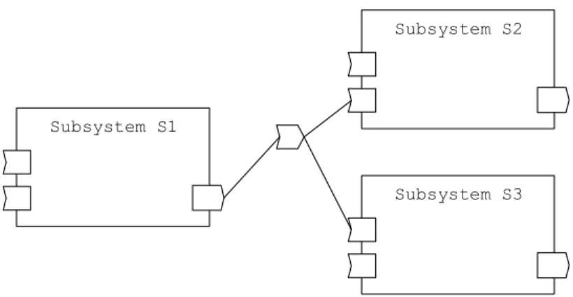
Subsystem S1
Figure 3.1 ProSys subsystem external view
A ProSys subsystem is specified by typed input and output message ports, as shown in the figure above. The ports describe what kinds of messages the subsystem receives and sends. Subsystems are active, which means that they can perform activities periodically on their own and not just as a reaction to external stimulus. They can contain reactive parts as well.
Communication between subsystems is modeled with message channels. Channels are used to connect output to input message ports. Message channels thus provide some additional functionality other then being a primitive message carrier, such as the possibility to associate information about the kinds of information being carried, and also to define some data initially required by the system to be available on the channel. Channels support n-to-n communication, i.e. more than one output and input ports may be connected to the channel. Message passing is asynchronous, i.e. sending a message is a non blocking action. The way in which incoming messages are handled is defined by the receiving subsystem.
Subsystem S1
Subsystem S2
Subsystem S3
Figure 3.2 ProSys subsystems communicating through a message channel
From the point of view of implementation, there are primitive and composite subsystems. Primitive subsystems are realized internally through ProSave components, by code conforming to the Progress subsystems runtime interface or by wrapping legacy code to make it compatible with the runtime interface.
Composite subsystems internally consist of subsystems and message channels. There are also connections that associate the message channels with message ports of the composite subsystem or the subsystems inside. This allows an input port, acting as a message consumer outside the component, to act as a message producer internally. Oppositely, an output port consumes messages on the inside and acts as a message producer from the outside.
Subsystem S1 Subsystem S2
Figure 3.3 ProCom composite subsystem
3.3.
Overview of ProSave
ProSave is a design language primarily intended for developing primitive ProSys subsystem with complex control functionally. Naturally, it is component based and a component is the fundamental building block in ProSave. A ProSave subsystem is thus constructed from interconnected components. Component can also be hierarchically structured.
ProSave components are completely passive, which means that they never initiate any activities on their own. Components don't have their own execution threads. They must therefore be activated by some external entity through some stimulus. After they have been activated (stimulated), they perform their functionality and return to the passive state.
It is important to note that ProSave components are design-time entities that do not exist as individual units in the final system that is being executed on some physical machine. During the deployment process, they are transformed into operating system tasks, which greatly improves efficiency of the final system, and this is of great importance in the target domain of ProCom.
ProSave architectural style is based on data/control flow that explicitly separates the flow of data from the flow of control.
In the following two sections, structure and the behavior of ProSave components are analyzed. The structure of a component is only its externally visible interface, whereas the internal structure is actually the components behavior.
3.3.1.
Structure of ProSave components
A ProSave component is the fundamental building block when constructing subsystem at the ProSave level. It is intended to contain small and non-distributed functionality. Component external structure consists of two major elements: ports and attributes. Component ports provide the way to access components functionality, and component attributes provide the way to access information about the component.
A ProSave component is a black-box from the outside, i.e. its internal implementation is not visible or directly accessible. This black-box view is considered reasonable, however some more complex analysis procedures may require a white-box view of a component, i.e. access to its internals. For example synthesis will definitely require a white-box view of a component considering that components are ultimately indistinguishable in the final system.
The separation of the data flow from the control flow is done by having two separate types of ports: data ports and trigger ports. The data flow is carried through the data ports and the control flow is carried through the trigger ports. From the direction point of view, both trigger and data ports can be of input and output type. Trigger ports are depicted as triangles and data ports as squares.
Component C1
Figure 3.4 ProSave component with two input ports (left) and three output ports (right)
Component behavior is modeled through the concept of services. When multiple services are provided by a single component, it is necessary to enable separate external access to them, and it is done by forming group of ports.
Service S1
Service S2
Figure 3.5 Port groups on a ProCom component with multiple services
3.3.2.
Behavior of ProSave components
Internally, the functionality of a component can be implemented in code (primitive component), or by interconnected subcomponents (composite component), but the distinction is not visible from the outside. Only primitive components are considered here, since composite components are ultimately also built from primitive components.
As described earlier, a ProSave component is passive, i.e. it never initiates any activities on its own and it does not have its own execution thread. Component can only react to some external stimulus, after which it will perform its functionality and produce some response on its output ports. Taking into consideration the data/trigger paradigm in ProSave, when the input trigger port is activated, it reads the current value at the input data port and starts processing this value according to the implemented functionality. When the calculation has finished, the result is produced at the output data ports on the components right side, and control is forwarded/returned via the output trigger port.
The concept of service was introduced in the previous section. Component will always provide at least one service, however it can provide more than one. This means that different services within a single component can produce parts of the result at different points in time. Each service therefore corresponds to some particular functionality that a component provides. Services are triggered independently and may run concurrently. Following elements constitute a single component service:
• input port group, that contains a single trigger port for service activation and a set of data ports for providing required data to the service
• set of output port groups, that contains a single trigger port for forwarding the control and a set of data ports for providing the result of services functionality.
The port to port-group relation and the port-group to service relation are clear from the figure above.
During its lifetime, a service state is changed from active to inactive and vice versa. Initially, all services of a component are in an inactive state. In this state it is possible for them to receive data and trigger signals on the input ports, but no computation is performed internally. When an input trigger port is activated, i.e. when a control signal comes to the component, all the data ports in the group are read in one atomic operation. When the data has been gathered the service switches into the active state and it performs its computation and produces output at the output group. The data and triggering of an output group are always produced in a single atomic step. When in the active state, a service can not be triggered again, i.e. attempts of reactivation on the trigger ports are ignored. This must be enforced by a design-time checker, and not at runtime to ensure high efficiency.
The functionality of each service is implemented by a non suspending C function. The component also has an init function which is called at system startup to initialize the internal state. A primitive component specifies a header C file and a source C file, where the init function and the service entry functions are declared and defined. The header file also declares the structs used for input and output to the services. By default, the naming of entry functions and argument structs is based on the names of services and ports, but explicit name mappings can also be supplied. [10]
During synthesis, the design-time components are transformed into runtime entities, such as operating system tasks. It is the responsibility of synthesis to ensure that the behavior of the runtime system is consistent with what is specified by the execution semantics and the ProSave design. For example, although the semantics view data transfer on different levels of nesting as separate activities, the final system may realize communication between two primitive components on different levels by a single write to a shared variable, ignoring the intermediate steps of activating input and output port groups, as long as the overall behavior is consistent with the execution semantics. [10]
Restrictions on data/control delivery are not complex. One rule is that trigger signals should not arrive to trigger ports before all data has arrived at data ports. Furthermore, when data reaches a port, it immediately overwrites the current value of that port. Also as mentioned earlier, triggering of a service in a active state is ignored. If the service is in the inactive state, then the values of the data ports of the triggered port group are atomically read, the state changes to active and the component performs its functionality.
4. CCL – Construction and composition language
4.1.
PECT perspective
CCL is part of the PACC (Predictable Assembly from Certifiable Components) initiative from the Software Engineering Institute at Carnegie-Mellon University. The PACC initiative has taken the prediction approach to CBD. It is the PACC position that predicting the behavior of components and assemblies is the only feasible future for CBD. It is therefore in the PACC objective to investigate and develop supporting technologies for making such predictions in a systematic and standardized way.
Considering that predictability is a fundamental issue in PACC it is necessary to define what a predictable assembly really is. Assembly of components is defined to be predictable if its run-time behavior can be exactly determined from the properties of its components and their interaction mechanisms. This is a simplified definition of predictability and it is discussed in more detail later.
Another fundamental issue in PACC is the certifiability of components. A component is said to be certifiable if its properties can be measured or verified by third-parties.
It is important to note that PECT is one possible approach to PACC. The fundamental assumptions of PACC are always the same: achieving assembly predictability from certifiable components. PECT offers one solution to this problem through the use of reasoning frameworks. PECT is, in short, a platform for predicting assembly behavior. It is therefore required from the PECT to support (1) the analysis of component and assembly properties and (2) the prediction of component and assembly properties. A PECT is generally made up of two parts: an analysis technology and a component technology.
It's important to emphasize that PECT is only a concept (a blueprint) that must be applied to some concrete component technology (component model). In order to „transform“ a existing component technology into a PECT, the constructive segment must be adapted, and an analytical segment must be defined and added. Through this process, a new component technology is created (PECT).
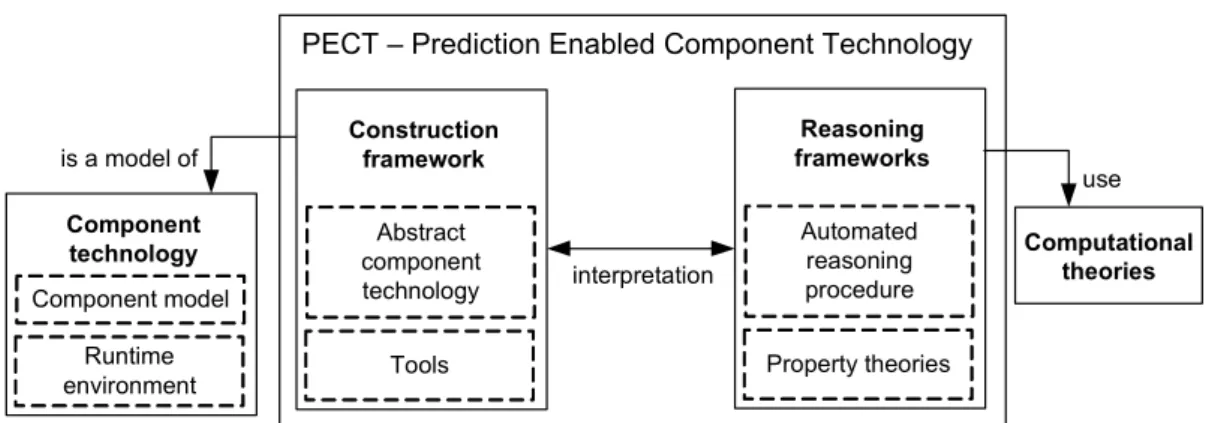
As mentioned already, a PECT has two main parts: a construction framework and one or more reasoning frameworks. Reasoning frameworks are connected to the construction framework via interpretations.
PECT – Prediction Enabled Component Technology Construction framework Abstract component technology Tools Component technology Component model Runtime environment is a model of Reasoning frameworks Automated reasoning procedure Property theories Computational theories use interpretation
Figure 4.1 Logical structure of Prediction-Enabled Component Technology
Each concrete component technology is „transformed“ into a PECT through the concept of the construction framework. The construction framework essentially consists of two elements: abstract component technology (ACT) and a construction language. It is the purpose of the construction language to describe a concrete component technology into a ACT. Therefore the ACT is a description of a particular component technology written in the construction language. PECT Construction Framework Reasoning Framework Construction
Language Component Abstract Technology Component technology Runtime environment Component model 1 1..* 1 1 1 1 1..* 1..* 1..* 1 specifies models
Figure 4.2 UML diagram of PECT concepts
In this case the construction language is the Construction and Composition Language (CCL). The purpose of using a single language is to enable the use of existing PECT tools with any component technology that has been transformed into a PECT.
A second purpose of the language is to enable the description of assemblies in the given ACT. Therefore the construction language (CCL) enables, among other things, the description of: (1) Assembly structure (component composition, etc.)
(2) Component behavior, interaction mechanisms (from the model), services (from the runtime)
(3) Properties required by different reasoning frameworks (these properties can be attached to different elements in the specification)
The majority approach to predicting the behavior of software systems today is software testing. Testing must be done very rigorously and the test results are of value only for the system being tested. Therefore the fundamental assumption is that by watching and analyzing the past, we can predict the future.
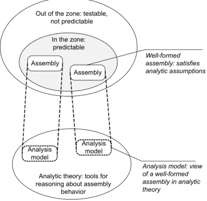
The PACC project takes a radically different approach and aims to enable prediction by creating analytical theories for entire classes of systems. As soon as a system satisfies the assumptions of a particular theory, it is predictable within that theory. The result of this is a specific view of the „world of all assemblies“ where we only recognize assemblies that are well-formed with respect to a analytical theory and thus that are predictable. All other assemblies are not predictable. The main goal then is to only build assemblies whose behavior can be predicted and we don't (and can't) predict the behavior of arbitrary non-valid assemblies. Therefore analytical theories impose certain design constraints.
The focus in the PACC project is on developing analytical theories for system properties of significant business value such as: reliability, safety, security etc.
In the zone: predictable Out of the zone: testable,
not predictable Assembly Assembly Well-formed assembly: satisfies analytic assumptions Analysis model Analysis model
Analytic theory: tools for reasoning about assembly
behavior
Analysis model: view of a well-formed assembly in analytic theory
Figure 4.3 Relation of the predictability zone and the analytic theory
The bases of an analytical theory are the assumptions that the theory makes and these assumptions influence the required knowledge about the component and confidence in it. For example a safety theory might require that a component specification contains a state machine
components cannot be idealistic black boxes because the theories require insight into component implementation and internal behavior.
This information required by the theories is acquired from the component through a analytic interface. These interfaces provide analysis-specific views of a component. A confidence in these interfaces is also essential in achieving overall prediction confidence. Therefore the PACC project has established such a foundation for building trusted and certified components.
It can be said that two fundamental premises for achieving predictable assemblies are achieving predictability by construction (building assemblies whose behavior can be predicted) and trusting the predictions with enough confidence. Confidence is achieved through rigorous empirical and formal validation because it is important to establish quantifiable trust.
4.2.
Construction framework
The construction framework is one of the two essential elements of a PECT. The other essential element are the reasoning frameworks which are connected to the construction framework via interpretations. Purpose of the construction framework is to support all of the usual construction activities done in component-based development.
Key feature of the construction framework is that it supports CBD construction activities in a technology-independent way. This is the purpose of ACT (Abstract Component Technology) which is an important part of the construction framework. The ACT is fundamentally a proxy for concrete component technologies. The ACT provides the language and notations for specifying component, assemblies, runtime environments etc. but in a technology-independent way. Along with the ACT, the construction framework comprises tools that provide support for construction activities.
Following is a description of essential CBD concepts and the way they are utilized in an ACT. As in CBD in general, a component is the fundamental building block of assembly. In contrast of typical CBD component definition as a black-box during usage, in the PECT view it is clear that much of components inner structure must remain exposed for the purpose of prediction and certification. In the context of a PECT, a component is considered an implementation that provides interfaces for third-party deployment through binding labels (pins) and can be independently deployed. In PECT, components final form is an executable binary, and not source code. A PECT component can be considered a unit of independent deployment if it has all of its dependencies on external resources specified and if it can be substituted by, or substitute of, another component. [3]
Components interfaces are realized through incoming sink pins, and outgoing source pins. Sink pins are responsible for incoming events to a component, whereas source pins are responsible for events outgoing from a component. The sink/source pin paradigm is equivalent to the provided/required interface paradigm present in other literature.
Component C1
Figure 4.4 Simple CCL component
Component behavior is specified in the form of reactions. Reactions essentially describe the connection between components sink pink and its source pins. This means that reactions define ways in which the component will react to external stimulus on its input pins. The fundamental reaction that a component can perform is to emit a event as a response to a incoming stimulus.
The minimal description of a reaction contains only information about sink and source pins involved in the reaction, however a more complex mechanism for specifying reactions is required. PECTs have primarily used CSP process algebra for describing reactions. The main drawback with CSP is its complexity. Recently, CSP has been replaced with a action language based on UML state charts. The state chart version is described in the CCL section.
It is important to note that reactions can be described through formal implementations in languages such as Java, or they can be described in an abstract way with languages such as CSP. Only requirement is that the reactions specification is parsable.
S0 S1 S2 R0 R1 RS0=S0 R0 R1 RS0 RS1=S1 R0 RS1 RS2=S1 R1 RS2 RC=RS0 RS1 RS2 S0 R0 R1 C C´ RC´ S0 R0 R1
Figure 4.5 Reaction specification in CSP (left) and an equivalent transition system (right)
Except for internal behavior of components, there is also external behavior among components, i.e. their interactions inside an assembly. Interactions describe composite behavior of multiple components, or more precisely, of multiple reactions. It is naturally required that components are interconnected before they can interact with each other. Components are therefore considered connected/composed if their pins are connected together. The existence of this connection between pins means it is possible for a interaction to occur but it is not obligatory. The behavior of a composition of components can be deduced from the behavior of its constituting reactions.
The PECT expects that the utilized concrete component technology has some form of a runtime environment. The term runtime environment is in other literature also known as: framework, container, platform etc. No matter what the name is, common and fundamental functionality is important. The environment [3]:
(1) provides services to components and assemblies (transaction, security, etc.). (2) manages resources (thread pools, database connections)
(3) manages component life cycles.
The environment can therefore be considered as a special kind of component with which other component/assemblies/environments may interact. It must also provide a concrete implementation of the interaction mechanisms (communication protocols) for the components to use. The environment must also provide support to assumptions required by reasoning frameworks. In this respect, the environment can be considered a component-aware virtual machine [3]. Structurally, the difference between components and assemblies/environments is that components cannot have internal structure whereas assemblies and environments can and must.
Environment E1
Clock Log
Figure 4.6 Simple CCL environment with two services
Generally there are synchronous and asynchronous modes of communication, and pins can further specialize this modes. Synchronous communication mode can be specialized by pins denoted in the construction framework language as sink mutex which enforce mutual exclusion on reaction within a component or by pins denoted as sink reenter which permit concurrent behavior of reactions. Asynchronous communication mode can be specialized by pins denoted as unicast or multicast which is self-explanatory. Synchronous pins can be visually distinguished from asynchronous pins because they have single-lined pin heads, whereas asynchronous pins have double-lined pin heads.
In principle, asynchronous communication is based on exchanging messages between parties communicating together. Synchronous communication, on the other hand, involves some kind of a procedure call, i.e. it requires some kind of a established communication channel between the communicating parties.
Summary of interactions provided by an environment:
• Asynchronous (event-based) interaction through an unbounded priority queue. Priorities are taken from the priorities of reactions that emit them.
source
sink Pri.
queue
• Asynchronous (event-based) interaction through an bounded FIFO queue of length n. source
sink [n]
Figure 4.8 Bounded asynchronous interaction in CCL
• Synchronous (call-return) interaction through a semaphore acquired by the calling reaction, i.e. the reaction is in a protected critical section.
source sink
Figure 4.9 Synchronous interaction in CCL
Components by themselves of course have no purpose and they must be composed into assemblies. Assembly is therefore a set of components that can interact. Assemblies themselves have no behavior of their own, i.e. their behavior is indirectly the behavior of their components. Assemblies can be contained by other assemblies, thus forming a structural hierarchy. An assembly provides constructive closure to a component which means that all components interactions are confined only to its immediate assembly. Since interactions among components are provided by the environment, each assembly is associated with exactly one environment.
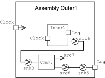
Assemblies are subject to the same type/instance paradigm as well as components and environments. For the purpose of achieving assembly hierarchy, i.e. having assemblies inside assemblies, an assembly can expose a particular pin that belongs to one of its contained components. Assembly Inner1 Comp 1 Comp 2 Clock src1 Log snk1 src2 listen src3 snk2 src4 src5
Assembly Outer1 Clock Log Inner1 Clock Log Comp3 src6 src7 src8 snk3 snk5
Figure 4.11 Assembly hierarchy through exposed pins
4.3.
Reasoning frameworks
The purpose of the reasoning framework is to analyze and predict the behavior of assemblies based on the description of properties of components and assemblies. Reasoning frameworks contain concepts and theories required to analyze and predict assembly qualities. Naturally, different reasoning frameworks are required to predict different runtime qualities. They use different component properties as inputs and give different requirements on what is and what is not an analyzable design.
The reasoning framework is essentially a way PECT packages the complexities of model checking technologies combined with component technologies. This allows the developer to predict the behavior of component-based systems without having expertise in analysis technology.
The interpretation is the link between the ACT (only 1 in a PECT) and each reasoning framework (at least one in a PECT). The purpose of the interpretation is to relate concepts from both frameworks. More formally, the interpretation is used during the translation of the construction language assembly specification into a reasoning framework understandable language. Therefore, reasoning frameworks are applied to assembly specifications by means of formal interpretations that generate analysis models from CCL specifications. Most interpretations use general CCL information, but specific analysis information is provided through CCL annotations.
The reasoning framework used in PACC is Comfort. Comfort is a model checking reasoning framework that provides a way to incorporate model checking techniques into a PECT. Fundamentally, formal verification implies having a mathematical model of a system and describing system properties in a formal language. If the system behaves according to its specifications, then it is said that the model satisfies the specification.
What model checking brings is automation, thus model checking is a completely automated form of formal verification that checks if a system satisfies a constraint by exhaustively searching through all possible states of the system. This exhaustive searching eliminates classical testing coverage problems. Model checking verifies finite-state concurrent systems.
This limitation allows complete automation. Also, model checking will always terminate with a yes or no answer, i.e. the model satisfies or does not satisfy the constraints.
It is important to note that the restriction to finite-state systems is not a disadvantage because it is still applicable to a lot of important classes of systems, such as hardware controllers, communication protocols, etc. Non-finite software may be verified if variable values are assumed over finite domains. This is also not a restriction because many important classes of systems, such as message queues can be restricted from infinite to finite queue lengths.
4.4.
Component certification
Achieving assembly predictability is a fundamental issue in PACC. A crucial condition for this is trusting the components that make up the assembly. PACC acknowledges that components are possibly subjects to third-party composition, which is reason enough to have a sound mechanism for providing trust in components. Since components are now days mostly shipped as binary code ready for execution it is important to create certified binaries, i.e. binaries that are trustworthy. But for a consumer to believe that a component is trustworthy, he must be able to verify this in a formal way.
A core idea used in PACC is proof-carrying-code (PCC) concept. Considering that a consumer will always request that a component satisfies a certain policy, the idea of PCC is to create a proof that the component satisfies this policy, embed the proof into the component binary and then ship it as a single unit. A consumer can then verify the validity of the proof on his own.
Policies most used today are safety policies, while proofs require considerable resources because of their size. PCC expands the policy set to include both safety and liveness policies. A linear temporal logic called SE-LTL is used to specify these policies. SE-LTL was also developed as a part of the PACC project. PCC uses automated model checking techniques for generating invariants and ranking functions required for proof construction. PCC also uses state-of-the-art SAT (Boolean satisfiability) technology to reduce the size of proofs to minimum.
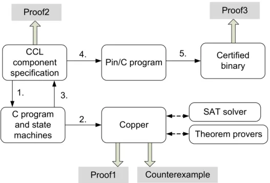
CCL component specification Proof1 C program and state machines Copper SAT solver Theorem provers Pin/C program Certified binary
1. 2. Counterexample Proof2 3. 4. 5. Proof3
Figure 4.12 PECT certification procedure
Figure above describes the certification procedure. Certification procedure begins with a CCL specification of a component assembly. The specification will contain a structural and behavioral description of the assembly as well as the safety and liveness policies that need to be certified. Required policies are specified in SE-LTL temporal logic.
The specification is then transformed (step 1.) into a form understandable by a model checker. This form is made up of C code and finite state machine specifications.
The model is transferred (step 2.) to the software model checker Copper. During its work Copper uses functionality of external SAT solvers and theorem provers to produce results. One possible outcome from Copper is a proof (Proof1) that the given model in fact satisfies given policies. The other possible outcome is a counterexample demonstrating why the model doesn’t satisfy the policies. What Proof1 really means is that the (C+FSM) model of the given CCL specification satisfies the given policies.
This must also be proven for the CCL specification itself which will establish the correctness of the interpretation from the specification to the model. Therefore Proof2 is generated which proves (step 3.) that the CCL specification was correctly reverse-interpreted from the model. The CCL specification is transformed into a Pin/C program runnable in a Pin runtime environment. This transformation works on the CCL specification, but also on the proof (Proof3) that the specification is correct, thus generating proof that the Pin/C program is also correct and satisfies given policies.
4.5.
Pin component technology
The Pin component technology is the only concrete technology that has so far been utilized for purposes of a PECT. As every component technology, Pin is comprised of a component model and a runtime environment. The component model defines the logical level of component and application structure as well as general interaction rules. The runtime environment, on the other hand, implements these rules and provides basic services, such as resource management, communication etc.
Pin has been completely developed at the SEI institute as a separate component technology, but has been developed for use in a PECT.
The target class of systems are embedded, safety-critical and time-critical systems. This means these systems are very small in implementation. It also means the implementation is very transparent because a lot of hiding would be too costly, unnecessary and thus counterproductive for this class of systems. Pin has been successfully implemented and used in real applications.
It is important to note that generally PECT is not formally restricted to the usage of Pin. Since PECT is a concept, i.e. a blueprint, it can be applied to any concrete component technology. However up to date, only Pin has been successfully used for a PECT implementation.
While designing Pin, some overall design objectives were kept in mind. (1) A simple programming model was required, as well as a very simple execution model that supported the UML state chart semantics. This requirement is important from both the usability and automation viewpoint, since a simple model simplifies the translation of code. Also changes to the Pin implementation are less likely to reflect on code generators. Also UML, as a widely spread language, enables the specification of component behavior as well as a basis for formal development, in a standard language. (2) A mechanism was needed to enable enforcement of external design and implementation constraints. (3) Only most basic features required for a PECT were introduced.
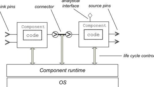
Component runtime OS
code code
connector
sink pins source pins
life cycle control
Component Component
analytical interface
4.6.
PACC Starter Kit
The PACC starter kit is a complete software solution with all the technologies developed in the PACC project combined together to provide a usable tool. The starter kit is based on Eclipse.
Main functionality provided by the starter kit:
• specification of components and assemblies of components in CCL.
• prediction of component and assembly behavior through behavior analysis
• generating binary code that implements the specifications
For the purpose of component and assembly specification, the Kit provides a CCL parser and the CCL compiler to generate implementations of the specifications in the target Pin component technology. The Kit thus contains the Pin component technology, i.e. the component model API and the runtime environment.
From the analysis and prediction perspective, the Kit contains a performance analysis reasoning framework that can be used to analyze worst and average performance of component and assemblies specified in CCL. A generalized rate monotonic scheduling theory is used as a supporting analytical theory. The Kit also contains a behavior analysis reasoning framework for behavior verification with model checking as the supporting analysis technology. A security analysis reasoning framework is also included for finding buffer overflows in C programs also with model checking as the supporting analytical technology. Finally, a memory analysis reasoning framework is included for predicting minimum page file sizes used by assemblies.
4.7.
CCL – Construction and composition language
PACC initiative is based on using PECT's (Prediction Enabled Component Technologies) which include a component technology and one or more reasoning frameworks. The purpose of PECT is to enable the prediction of component and assembly behavior with respect to those frameworks. The prediction process is based on certifiable properties of components and their specifications. The language used for writing such specs is CCL. So CCL specifications represent everything a reasoning framework needs to know in order to predict component and assembly behavior. There are also a number of automated tasks in the entire prediction process that can be automated with the help of CCL.
Information that CCL specifications provide can be divided into three general groups:
• structural information
• behavioral information
• analysis specific information.
Only structural and behavioral specifications will be further analyzed as they are most significant in defining a component.
• component annotations – used for supplying additional information to the Pin code generator (optional)
• variable declarations – standard programming language variables (optional)
• structural specification – description of components externals (pins)
• behavioral specification – description of components internal behavior (reactions)
• verbatim code – CCL mechanism that enables the use of arbitrary C code as part of components behavior
CCL is formally defined through a language grammar. The starter kit provides an environment that supports the creation, validation and further usage of a CCL specification. The grammar is textual therefore CCL specifications are created and used only in pure textual form. Graphical notation may be used informally when specifying component structure and behavior but it is currently not supported by the development environment.
Structural features of CCL are later introduced in graphical notation, and then in the formal text notation as they are defined in the grammar. The graphical notation used corresponds to the way components and assemblies are represented in the Pin component technology. Usage of informal Pin notation makes sense since Pin concepts are mirrored in the language. It is also important to mention that CCL is therefore an IDL to the Pin component technology. Behavioral specifications of components may be informally given in standard UML state-chart notation given that the action language is based on the state-state-chart language. However a CCL specific syntax is used for the textual representation of UML state-charts. CCL is therefore also a surface syntax for UML state-charts.
Part of the language responsible for specifying component behavior is called the action language. The CCL action language is C-like in syntax but is much more restrictive than C. An example of a restriction is the absence of pointers in the language. CCL follows the general C syntax for variable declaration: the type name and variable name are followed by an optional initializing expression. The initializing assignment occurs exactly once, when the component is instantiated. CCL supports the string, boolean, enum and several int and float types. Multi-dimensional array types can also be defined using C typedef syntax. Arrays in CCL are much more restrictive than C arrays, for example, the bounds of all array dimensions must be statically defined.
4.7.1.
Structural elements of specifications
Primary focus here is on the specification of a single component. In CCL, as well as CBD in general, a component is the fundamental structural element of an assembly. The PACC project recognizes the concept of a component in the context of component types and component instances. In CCL the concept is formalized through the component keyword used in formal specifications of a CCL component type.
The structural part of the component specification specifies how the component interacts with its environment. In CCL the only way a component interacts with its environment is through its pins. There are no other ways of communication with the component. The structural specification defines for example the type of communication with the environment, type of data exchanged with the environment etc.
There are two types of pins: sink pins and source pins. The component receives stimulus for communication only through its sink pins and it initiates communication with the environment only through its source pins. Pins are formalized in CCL through the use of sink and source keywords.
Figure below shows the graphical syntax used in CCL for describing the components structural information. Component C1 snk1 snk2 src1 src2 pin name
sink pins source pins
pin head
component component name
Figure 4.14 CCL component structural information
By convention, sink pins are placed on the left side of the component, and the source pins are placed on the right side of the component, which according to the CCL specification, „allows, at the cost of some cultural bias, to read the component from left to right“.
Generally there are synchronous and asynchronous modes of communication, and pins further specialize these modes. Type of communication supported on a pin is defined in the component specification using the synch and asynch keywords.
Synchronous communication mode can be specialized by pins denoted as sink mutex which enforce mutual exclusion on reaction within a component or by sink reenter which permit concurrent behavior of reactions. Asynchronous communication mode can be specialized by pins denoted as unicast or multicast which is self-explanatory. Synchronous pins can be visually distinguished from asynchronous pins because they have single-lined pin heads, whereas asynchronous pins have double-lined pin heads.
In principle, asynchronous communication in CCL is based on exchanging messages between parties communicating together. Synchronous communication, on the other hand, involves some kind of a procedure call, i.e. it requires some kind of an established communication channel between the communicating parties. However, CCLs specification notes that it is not always implemented in this way.
Type of data that can be transferred through component pins is defined by the pin data interface. The data interface of a single pin is a set of simple data types that can be transferred through the pin. CCL supports transfer of very common data types such as: int, short, byte, bool, float, double, string, void or custom types.
In the figure below is an example of a simple component and its basic CCL structural specification. Component has a single sink pin snk1, and source pins src1 and src2. All pins
are intended to be used for asynchronous communication. None of the pins have declared arguments which mean this component will not exchange any data with the environment.
Component C1 component C1(){ sink asynch snk1(); source unicast src1(); source unicast src2(); //implementation } snk1 src1 src2
Figure 4.15 CCL component structural specification
The component runtime environment is also modeled in CCL and it also conforms to the type/instance paradigm. The keyword environment is used for defining a environment type specification. Environments generally have two important roles which are implemented in CCL, they provide services and interaction mechanisms. Detailed CCL specifications of environments are expected to be delivered by PECT developers, since environments are expected to be reused for multiple systems.
Services are defined in the environment through the keyword service. They are basically simple components maintained and provided by the environment to its containing assemblies and indirectly components. The reason why the keyword component was not used for the specification of services is that differences in well-formedness rules may exist between environment components and application components. A very specific difference between services and components is that components are purely reactive, i.e. they cannot begin activity on their own, whereas services can, in fact it is expected of them. Another fundamental difference is that services represent environment supplied code that can communicate with the world outside of the assembly (such as device drivers), while all component communication is explicitly represented with its pins. This is why service instances are shown on the border of the assembly instance, as will be seen later.
Environment E1
Clock Log
Figure 4.16 CCL services in an environment
Assemblies are essentially groupings of components that work together to provide some functionality, i.e. functionality of the assembly. In CCL assemblies also follow the type/instance paradigm like component, environments and services. Assemblies are defined using the keyword assembly which introduces a new assembly type. In spite of that, the difference between assembly type and assembly instance is not always as clear as the one
Assemblies can exist only inside a environment which provides the services and interaction mechanisms they require. Interaction mechanisms between components inside an assembly rely on the mechanisms provided by the environment.
Definition of an assembly in CCL must therefore be explicitly related to a specific environment. This is done through parameterization as shown in figure 1.13. When an assembly is defined in an environment with existing services, the quantity of service instances is unknown in advance. Therefore the assembly specification can make an assumption about this using the keyword assume.
assembly Inner()(E){ assume{ E:Clock clock(); E:Log log(); } //implementation } Assembly Inner clock log
Figure 4.17 CCL assembly specification
Components are added to the assembly by instantiation. In order to enable component interaction they must be connected. In CCL components are connected using the ~> operator. It connects the left operand (source pin) to the right operand (sink pin). The language specification defines several rules that connections must conform to, for example: source and sink pins must have compatible interaction types (unicast source is not compatible with mutex sink but is compatible with asynch sink), each consume data parameter must correspond to a produce parameter and their types must also be compatible,
assembly Inner1 comp1 comp2 clock log snk1 snk2 src1 src2 src3 src4 assembly Inner()(E){ assume{ E:Clock clock(); E:Log log(); } Comp comp1(),comp2();//instances ... }
Figure 4.18 CCL component instantiation within an assembly
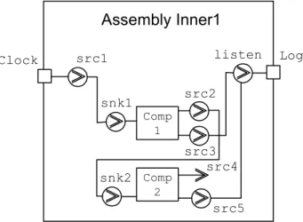
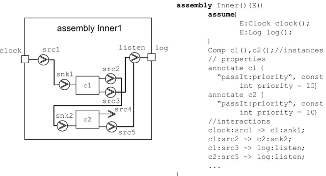
As mentioned earlier, CCL specifications also contain analysis specific information. This information concerns limitations imposed by the reasoning framework. A reasoning framework may specify well-formedness rules which might have to be imposed through additional properties in the CCL specification. CCL uses the annotation mechanism for this purpose. Example of such specific properties, for example thread priority specification is shown in figure 1.15.
assembly Inner1 c1 c2 clock src1 log snk1 src2 listen src3 snk2 src4 src5 assembly Inner()(E){ assume{ E:Clock clock(); E:Log log(); } Comp c1(),c2();//instances // properties annotate c1 { “passIt:priority“, const int priority = 15} annotate c2 { “passIt:priority“, const int priority = 10} //interactions clock:src1 ~> c1:snk1; c1:src2 ~> c2:snk2; c1:src3 ~> log:listen; c2:src5 ~> log:listen; ... }
Figure 4.19 Example of providing analysis specific information through CCL
Considering that assemblies by them selves have no structure except from their components, and thus have no interface on their own, it follows that there must be a way to connect assemblies together. Connecting them together actually means connecting their inner components together. Since their components are not directly visible or accessible from the outside, CCL provides a mechanism for exposing certain component pins from inside the assembly. Other assemblies with their exposed pins can then connect to this assembly through its exposed pins. Not surprisingly, CCL uses the keyword expose to specify this concept.
assembly Inner clock log ext1 assembly Inner()(E){ assume{ E:Clock clock(); E:Log log(); } Comp c1(),c2();//instances //interactions clock:src1 ~> c1:snk1; c1:src2 ~> c2:snk2; c1:src3 ~> log:listen; c2:src5 ~> log:listen; expose {c2:sr4 as ext1} }
Figure 4.20 Example of exposing assembly pins with CCL
Final important structural concept that needs to be covered is the assembly aggregation, i.e. assemblies within assemblies. This is done in a way very similar to components and is shown in figure 4.21.