Working towards
a cleaner future
Paramount two
Wall hung condensing boiler
30 – 115kW
120
-393 632
.4 04.08 F
h
Table of contents
1. Regarding this Manual. . . .4
1.1 Content of this manual . . . .4
1.2 Used symbols . . . .4
1.3 For whom is this manual intended? . . . .4
2. Safety. . . .5
2.1 General safety precautions . . . .5
2.2 Use . . . .5
2.3 Installations/Instructions . . . .6
2.4 Regulations and standards . . . .6
2.5 C.E. Approvals . . . .7
2.6 Conformity declaration . . . .8
3. Technical Data. . . .9
3.1 Dimensions and connections PARAMOUNT two 30/40 . . .9
3.2 Dimensions and connections PARAMOUNT two 60-115 . . 11
3.3 Technical Data PARAMOUNT two . . . 13
3.4 Wiring diagram . . . 14
3.5 Sensor value tables. . . 15
4. Before installation . . . .16
4.1 Combustion air supply. . . 16
4.2 Corrosion protection. . . 17
4.3 System water quality . . . 17
4.4 Use of additives (e.g. hardness stabilsisers, frost protective agents, sealing agents) . . . 17
4.5 Notes for installation location . . . 18
4.6 Clearances . . . 18
4.7 Application example . . . 19
5. Installation . . . .21
5.1 Connecting to the heating system . . . 21
5.2 Condensate. . . 21
5.3 Filling the heating system . . . 21
5.4 Flue connection . . . 21
5.5 Flue system. . . 22
5.6 Flue terminal positioning. . . 23
5.7 Gas connection . . . 24
5.8 CO2 -Content. . . 25
5.9 Changing over from LPG to natural gas and vice versa. . 25
5.10 Gas valve . . . 26
5.11 Guide Values for Injector Pressure . . . 28
120
-393 632
.4 04.08 F
h
6.2 Temperatures for heating and DHW . . . 30
6.3 Individual time program . . . 30
6.4 Programming of necessary parameters . . . 31
6.5 Emergency operation (Manual operation) . . . 31
6.6 Instruction for the customer. . . 31
7. Operation . . . 32
7.1 Operation elements . . . 32 7.2 Displays . . . 33 7.3 Operation . . . 338. Programming . . . 36
8.1 Programming procedure . . . 36 8.2 Modification of parameters . . . 37 8.3 Setting table . . . 388.4 Explanations for setting table . . . 46
9. General . . . 61
9.1 Room unit RGT . . . 6110.Servicing . . . 62
10.1 Maintenance work . . . 62 10.2 Replace air-vent . . . 62 10.3 Condensate siphon . . . 6210.4 Removing gas burner. . . 63
10.5 Protection against electrical shock . . . 66
10.6 Boiler view PARAMOUNT two . . . 67
10.7 Dismantling the heat exchanger . . . 70
10.8 Check electrodes . . . 70
10.9 Control and regulating centre LMU . . . 71
10.10Fault switch-off . . . 71
10.11Fault code table . . . 73
10.12Operation phases of control and regulation centre LMU (Press information button) . . . 74
Regarding this Manual
120
-393 632
.4 04.08 F
h
1.
Regarding this Manual
Read this instruction booklet thoroughly before operating the boi-ler!
1.1
Content of this manual
This manual contains the instructions for the installation of the PA-RAMOUNT two for standard applications with 1 heating circuit and/ or 1 DHW circuit (WWF tank sensor required for DHW).
Further applications can be made available (for multiple boilers and multiple zones) by installing extension modules (clip-ins). Keep all documents at the installation location of the boiler!
1.2
Used symbols
1.3
For whom is this manual intended?
This installation manual is intended for the heating specialist. Danger! Danger exists for body and life in case it is not observed.
Danger of electric shock! In case it is not observed, danger from electricity exists for body and life!
Attention! If warning is not observed, danger exists for environ-ment and the device.
Note/tip: Here, you can find background information and useful tips.
120
-393 632
.4 04.08 F
h
2.
Safety
Danger! Absolutely observe the following safety instructions! Otherwise, you may endanger yourself and others.
2.1
General safety precautions
Installation of System:
Important: The boiler must be commissioned following completion of installation. Operation of an un-commissioned appliance may cause injury to personnel and damage to the boiler unit which would invalidate the warranty.
Commissioning must only be carried out by personnel approved and competent to do so. This facility is available from Potterton Com-mercial Service Office.
Important: the boiler unit is supplied in accordance with Potterton Commercial quality assurance plan registered to meet the require-ments of BSN ISO 9002. A condition of the supply of the appliance for compliance with this is the return of the appliance commissio-ning report.
Electrical Installation:
The electrical installation work must be carried out by a qualified electrician.
Gas Installation:
Boiler installation as well as commissioning, servicing and mainte-nance must be carried out by an approved gas installer. For use with natural gas (G20) nominal supply pressure 20 mbar (LPG opti-on available).
2.2
Use
The POTTERTON PARAMOUNT two wall hung condensing boiler is available in six sizes with outputs from 30 kW to 115 kW.
They are CE marked for use on Natural Gas (LPG) on open vented systems (min 1 bar) and are suitable for use on sealed systems with a maximum operating pressure of 3 bar (30/40 kW), 4 bar (60 - 115 kW). Refer to relevant British Standards and Codes of Practice for installation of condensing boilers on sealed system. The heat exchanger consists of aluminium - silicon alloy, which allows very compact and lightweight boiler construction. The fully premix bur-ner works in a modulating range of between 25 % and 100 %. There-fore the boiler can adapt to the particular heat requirements of the circuit. The gas/air ratio control ensures uniform CO2emissions
and low NOx. This is obtained by comparing the target boiler
tem-perature and actual boiler temtem-perature. If there is a difference between these two values then the internal microprocessor calcu-lates a new fan speed. The change in fan speed in turn changes the combustion chamber static air pressure which is monitored by the gas/air ratio control and the gas rate is adjusted thus maintaining the correct gas to air ratio in the boiler. This ensures that a uniform
Safety
120
-393 632
.4 04.08 F
h
gas/air ratio is maintained over the total range of the boiler
mo-dulation, and that constant CO2values are achieved.
For optimum utilisation condensing boilers should be operated at a low return temperature. However the PARAMOUNT two will also work at designed temperatures of 70/50°C. In the condensing mode as the return temperature is below the dew point (dew point is 53°C at 8.5 % CO2).
They fulfil EN 483 and EN 677, Type C. Installation types B23, B33, C13x, C33x, C43x, C63x. Emission value group G 61.
Category II2H3P.
2.3
Installations/Instructions
Before starting work a risk assessment should be carried out in the boiler house and its access to ensure a safe installation and wor-king environment. Any person installing or worwor-king on the boiler must be qualified and attention is drawn to the mandatory require-ments of C.O.R.G.I. registration for all gas installers.
Manual Handling: Any person or persons moving or lifting the boiler or any part there of should be trained in manual handling techni-ques and if necessary use suitable lifting equipment to reduce the risk of injury to themselves or other people.
2.4
Regulations and standards
The installation should comply with relevant British Standard Spe-cifications, Codes of Practice and current Building Regulations, to-gether with any special regional requirements of the Local Authorities, Gas undertaking and Insurance I.E.E. Regulations for the Electrical Equipment of Buildings. The installation of the boiler must be in accordance with the relevant requirements of:
Health and Safety at Work act 1974 Building Regulations 2006
Electricity at Work Regulation 1989
Management of H&S at Work Regulations 1998 Manual Handling Regulations 1992
Model Water By-Laws 1986
BS 7671: 1992 - Requirements for Electrical Installations, IEE Wi-ring Regulations Sixteenth Edition.
BS 5440: 2000: Part 1 - Specifications for Installation of Flues BS 5440: 2000: Part 2 - Specifications for Installation of Ventilation for Gas Appliances.
BS 6644: 2005 - Installations of Gas Fired Hot Water Boilers for in-puts between 60 kW and 2 MW.
BS 7074: 1989: Part 2 - application Selection and Installation of Ex-pansion Vessels and Ancillary Equipment for Sealed Water Systems. BS 6880: 1988 - codes of Practice for Low temperature Hot Water Systems.
EN 677: 1997 - Gas Fired Central Hating Boilers for Condensing Boi-lers with a nominal heat input not exceeding 70 kW.
CP 342:2 - Centralised Hot Water Supply Gas Safety (Installation and Use) Regulations 1998
120
-393 632
.4 04.08 F
h
IM/II - Flues for commercial and Industrial Gas Fired Boilers and Air Heaters.
IGE/UP/1 - Soundness Testing and Purging Procedure for Non Do-mestic Installations.
IGE/UP/2 - Gas Installation Pipe work, Boosters and Compressors for Industrial Commercial Premises.
Manufacturer's notes must not be taken in any way as over-riding statutory obligations.
2.5
C.E. Approvals
The CE approval symbol means that the boilerfulfils the basic re-quirements of the Gas Equipment Directive 90/396/EEC, the Low Voltage Directive 73/23/EEC as well as Directive 89/336/EEC (Electromagnetic Compatibility EMC) of the Council for Unification of Legal Regulations of the members Countries. The boiler fulfils the basic requirements of the Boiler Efficiency Directive 92/43/ EEC for condensing boilers.
Safety
120 -393 632 .4 04.08 F h2.6
Conformity declaration
Paramount two 30 - 115120
-393 632
.4 04.08 F
h
3.
Technical Data
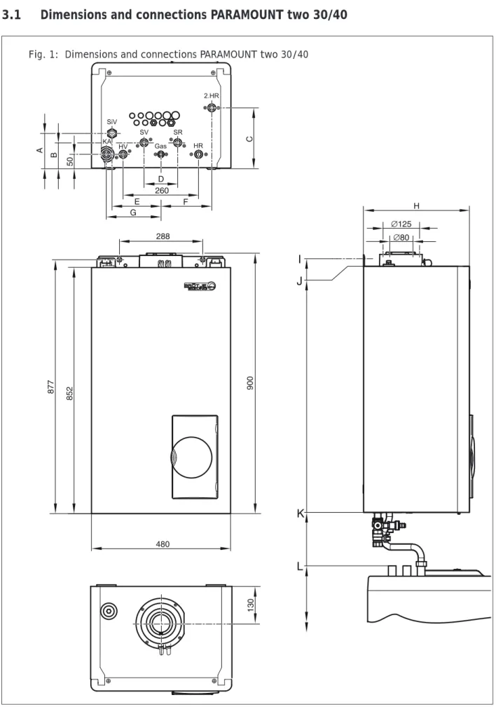
3.1
Dimensions and connections PARAMOUNT two 30/40
Technical Data
120
-393 632
.4 04.08 F
h
Table 1: Dimensions and connections PARAMOUNT two 30/40
Model 30 / 40
HV – Heating flow G 1“
HR – Heating return G 1“
Gas – Gas connection G 3/4“
SiV – Safety valve G 3/4“
KA – Condensate water connection Ø 25 mm
Dimension A [mm] 116
Dimension E [mm] 177
Dimension F [mm] 185
Dimension G [mm] 192
120
-393 632
.4 04.08 F
h
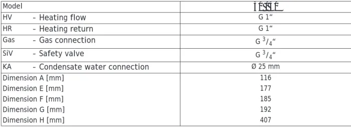
3.2
Dimensions and connections PARAMOUNT two 60-115
Fig. 2: Dimensions and connections PARAMOUNT two 60-115
160 110 aGR030B B C 851 883 975
Technical Data
120
-393 632
.4 04.08 F
h
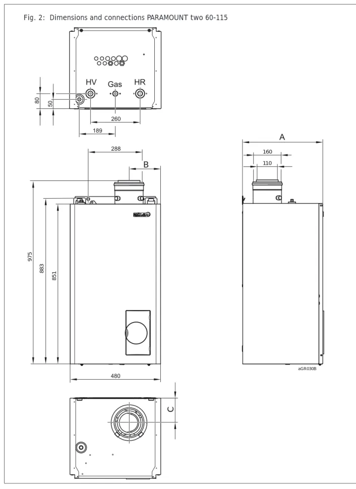
Table 2: Dimensions and connections PARAMOUNT two 60-115
Model Paramount 60 D Paramount 80 D Paramount 90 C Paramount 110 C HV – Heating flow G 1 1/2“ HR – Heating return G 1 1/2“
Gas – Gas connection G 1“
SiV – Safety valve G 3/4“
KA – Condensated water
connection Ø 25 mm
Dimension A [mm] 446,5 541,5 585
Dimension B [mm] 167,5 163
120
-393 632
.4 04.08 F
h
3.3
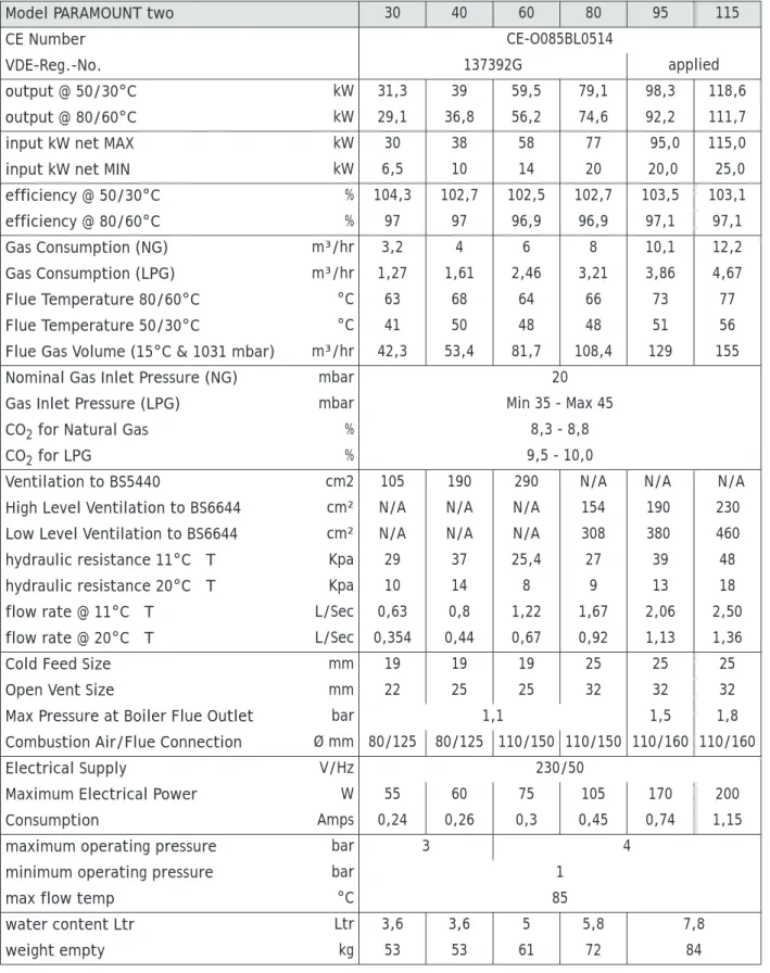
Technical Data PARAMOUNT two
Table 3: Technical data PARAMOUNT two
Model PARAMOUNT two 30 40 60 80 95 115
CE Number CE-O085BL0514
VDE-Reg.-No. 137392G applied
output @ 50/30°C kW 31,3 39 59,5 79,1 98,3 118,6
output @ 80/60°C kW 29,1 36,8 56,2 74,6 92,2 111,7
input kW net MAX kW 30 38 58 77 95,0 115,0
input kW net MIN kW 6,5 10 14 20 20,0 25,0
efficiency @ 50/30°C % 104,3 102,7 102,5 102,7 103,5 103,1 efficiency @ 80/60°C % 97 97 96,9 96,9 97,1 97,1 Gas Consumption (NG) m³/hr 3,2 4 6 8 10,1 12,2 Gas Consumption (LPG) m³/hr 1,27 1,61 2,46 3,21 3,86 4,67 Flue Temperature 80/60°C °C 63 68 64 66 73 77 Flue Temperature 50/30°C °C 41 50 48 48 51 56
Flue Gas Volume (15°C & 1031 mbar) m³/hr 42,3 53,4 81,7 108,4 129 155
Nominal Gas Inlet Pressure (NG) mbar 20
Gas Inlet Pressure (LPG) mbar Min 35 - Max 45
CO2 for Natural Gas % 8,3 - 8,8
CO2 for LPG % 9,5 - 10,0
Ventilation to BS5440 cm2 105 190 290 N/A N/A N/A
High Level Ventilation to BS6644 cm² N/A N/A N/A 154 190 230
Low Level Ventilation to BS6644 cm² N/A N/A N/A 308 380 460
hydraulic resistance 11°C ΔT Kpa 29 37 25,4 27 39 48
hydraulic resistance 20°C ΔT Kpa 10 14 8 9 13 18
flow rate @ 11°C ΔT L/Sec 0,63 0,8 1,22 1,67 2,06 2,50
flow rate @ 20°C ΔT L/Sec 0,354 0,44 0,67 0,92 1,13 1,36
Cold Feed Size mm 19 19 19 25 25 25
Open Vent Size mm 22 25 25 32 32 32
Max Pressure at Boiler Flue Outlet bar 1,1 1,5 1,8
Combustion Air/Flue Connection Ø mm 80/125 80/125 110/150 110/150 110/160 110/160
Electrical Supply V/Hz 230/50
Maximum Electrical Power W 55 60 75 105 170 200
Consumption Amps 0,24 0,26 0,3 0,45 0,74 1,15
maximum operating pressure bar 3 4
minimum operating pressure bar 1
max flow temp °C 85
water content Ltr Ltr 3,6 3,6 5 5,8 7,8
Technical Data
120 -393 632 .4 04.08 F h3.4
Wiring diagram
120
-393 632
.4 04.08 F
h
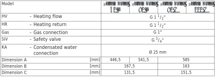
3.5
Sensor value tables
Table 4: Resistance values for outside temperature sensor ATF
Temperature [°C] Resistance [
Ω
] -20 8194 -15 6256 -10 4825 -5 3758 0 2954 5 2342 10 1872 15 1508 20 1224 25 1000 30 823Table 5: Resistance values for flow sensor, DHW sensor, return sensor, sensor B4 Temperature [°C] Resistance [
Ω
] 0 32555 5 25339 10 19873 15 15699 20 12488 25 10000 30 8059 35 6535 40 5330 45 4372 50 3605 55 2989 60 2490 65 2084 70 1753 75 1481 80 1256 85 1070 90 915 95 786 100 677Before installation
120-393 632
.4 04.08 F
h
4.
Before installation
4.1
Combustion air supply
Concentric Flue Applications
The air supplied for the boiler space ventilation shall be such that the maximum temperatures shall not exceed 25°C at floor level or 100 mm above, 32°C at mid level (1.5 m above floor level) and 40°C at ceiling level or 100 mm below ceiling level.
Refer to BS5440 2000 for boiler installations up 70 kW net and BS6644 2005 for boilers above 70 kW net for further details. The following tables give the total free area of the vents required for single boiler installations in room sealed and open flue applica-tions.
Clean combustion air!
The PARAMOUNT two must only be installed in rooms with clean combustion air. Under no circumstances must e.g. pollen or the li-kes enter through the intake openings into the inside of the PARA-MOUNT two.
Table 6: Conventional flue Applications
Model PARAMOUNT two 30 40 60 80 95 115
Vent Position cm² Low Level LevelHigh LevelLow LevelHigh LevelLow LevelHigh LevelLow LevelHigh LevelLow LevelHigh LevelLow LevelHigh In a room direct to
outside cm² Single105 - Single190 - Single290 - 308 154 380 190 460 230
In a compartment
direct to outside cm² 252 126 380 190 580 290 770 385 950 475 1150 575
In a compartment
via a room cm² 504 252 760 380 1160 580 - - -
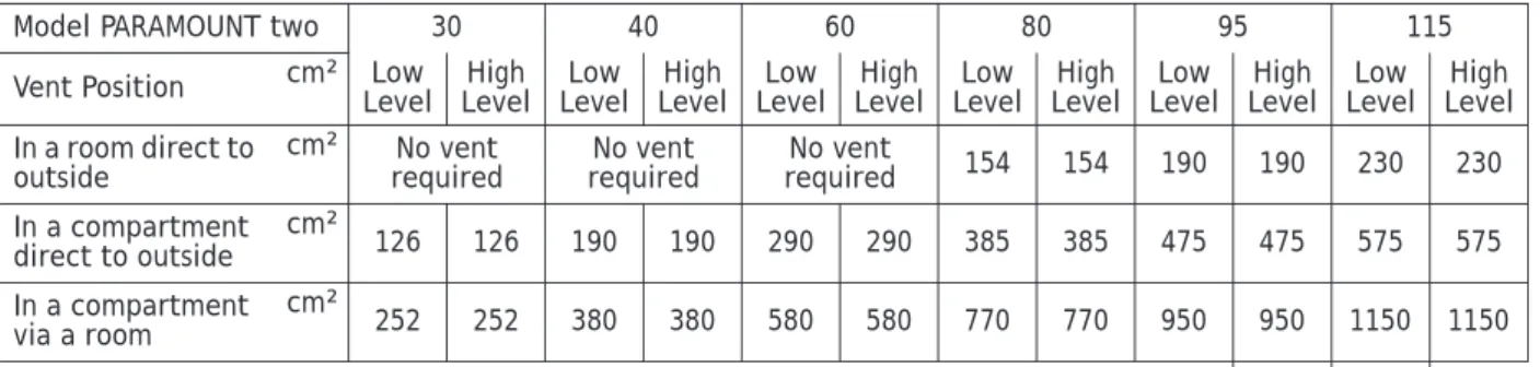
-Table 7: Ventilation for use with room sealed applications
Model PARAMOUNT two 30 40 60 80 95 115
Vent Position cm² Low Level LevelHigh LevelLow LevelHigh LevelLow LevelHigh LevelLow LevelHigh LevelLow LevelHigh LevelLow LevelHigh In a room direct to
outside cm² requiredNo vent requiredNo vent requiredNo vent 154 154 190 190 230 230
In a compartment
direct to outside cm² 126 126 190 190 290 290 385 385 475 475 575 575
In a compartment
via a room cm² 252 252 380 380 580 580 770 770 950 950 1150 1150
Table 8: Mechanical Ventilation with conventional flue
Mechanical Inlet m³/s Mechanical Extract m³/l
PARAMOUNT two 30 0.03 0.02 PARAMOUNT two 40 0.04 0.03 PARAMOUNT two 60 0.06 0.04 PARAMOUNT two 80 0.06 0.04 PARAMOUNT two 95 0.07 0.04 PARAMOUNT two 115 0.08 0.05
120-393 632
.4 04.08 F
h
4.2
Corrosion protection
The combustion air must be free from corrosive elements - espe-cially fluorine and chlorine containing vapours which are found, for example, in solvents and cleaning agents, propellant gases etc. When connecting boilers to under-floor heating systems, employ-ing plastic pipe work which is not impervious to oxygen, heat ex-changers must be used for separation purposes.
4.3
System water quality
To ensure the boiler heat exchanger remains in good condition it is essential to condition and monitor the system water to the follo-wing criteria:
– Water hardness: if the system fill water has a hardness in excess of 259 mg/l (17,5°Clark) the water should be softened prior to filling the system to ensure that excessive scaling does not oc-cur within the heat exchanger.
– Water acidity: the system fill water should have pH value bet-ween 7 - 8.3 to ensure corrosion of the heat exchanger does not occur.
– Copper ions: the copper content of the system water should be less than 0.05 mg/l. If large quantities of copper are present red and black copper oxide Cu2O and CuO and grey/green copper
carbonate, CuCo2 will be produced. Copper will corrode any
iron and aluminium within the system. A special water treat-ment company should be consulted if in doubt.
4.4
Use of additives (e.g. hardness stabilsisers, frost protective agents, sealing agents)
If, in a special case, a need exists to use additives in a mixture (e.g. hardness stabilser, frost protecion agent, sealing agent,etc.) it has to be observed that the agents are compatible with each other and the pH-value is not altered. Preferably, agents from the same manufacturer should be used.The instructions of the additive manufacturer have to be observed. Released additives
Currently, the following agents have been approved by POTTERTON Commercial:
– “Full heating protection“ from Fernox – “Sentinel 100“ from GE Betz
As a single frost protection agent, also Tyfocor® L may be used. If not approved agents are used, the guarantee becomes void! When softener facilities are used, water softening to a hardness of minimum 6 to 8 °dH is recommended.
The pH-value must not exceed the permissable value of 8.3. Maintenance instructions
The water hardness of the heating water has to be checked within the scope of the recommended maintenance of the boiler (every two years) and, possibly, the respective amount of additive has to be added.
Before installation
120-393 632
.4 04.08 F
h
4.5
Notes for installation location
Attention! When first installing the PARAMOUNT two for heating operation or in connection with a DHW storage, the following has to be observed:
In order to prevent damage to the boiler due to water quality, par-ticularly due to leakages in the tank, suitable precautionary measures should be taken regarding installation.
Installation room
• The installation room must be dry, the room temperature must be between 0 and 40°C.
The installation location has to be selected, especially, with re-spect to ducting of the flue. When installing the boiler, the speci-fied clearances have to be maintained.
Sufficient space should exist in the front to carry out inspection and maintenance work.
4.6
Clearances
When installing the PARAMOUNT two , the following clearances must be considered:
FRONT - access for maintenance SIDES - minimum 20 mm
120-393 632
.4 04.08 F
h
4.7
Application example
Application example: A pumped heat
circ
uit with room control and DHW
circuit
Before installation
120-393 632
.4 04.08 F
h
120
-393 632
.4 04.08 F
h
5.
Installation
5.1
Connecting to the heating system
Connect heating circuit with flat seal screw connections to boiler flow and return connections.
In the case of old systems, the whole heating system should be tho-rougly flushed before installation.
Attention! It must not be possible to shut-off the connecting pipe between the boiler and the safety valve.The installation of pumps and valves or pipe restrictions is not allowed.The blowpipe of the safety valve must be installed in such a way that no pressure incre-ase is possible, when the valve operates. It must not be taken to the outside; the outlet must be free and observable.
5.2
Condensate
Direct introduction of the condensed water into the domestic was-te wawas-ter syswas-tem is only allowed, if the sywas-tem is made from corro-sion-resistant materials (e.g. PP-pipe, stoneware, or similar). The condensate must run freely into a tundish. A syphon trap must be installed between tundish and waste water system. The con-densate hose of the PARAMOUNT two must be passed through the opening in the bottom. If no draining possibility exists underneath the condensate outlet, the use of a neutralising and lifing facility is recommended.
Attention! Fill the condensate drain with water before operating. For this, fill 0.25 l of water into the exhaust gas flue pipe before assembly of the flue system.
5.3
Filling the heating system
• Fill the heating plant via the return of the PARAMOUNT two. • Check tightness (max.water test pressure 34 bar).
5.4
Flue connection
For the operation of PARAMOUNT two, the flue must be designed for flue temperatures below 120°C (flue type B). Potterton Com-mercial offer a comprehensive optional flue components approved for the boiler (see fig. 3).
Installation
120
-393 632
.4 04.08 F
h
The enclosed assembly instruction for the flue system has to be ob-served.
5.5
Flue system
Additional Bends
Reduction of total length of flue pipe by: – per 87°elbow = 1.00 m
Fig. 3: Flue options
Model
PARA-MOUNT two 30/40 60 80 95 115
Flue Type
Flue Size Flue Max
Length* Max. No of Bends (90°) Flue Size Flue Max
Length* Max. No of Bends (90°) Flue Size Flue Max
Length* Max. No of Bends (90°) Flue Size Flue Max
Length* Max. No of Bends (90°) Flue Size Flue Max
Length* Max. No of Bends (90°) C13 (Balanced Flue) 80/125 10(5) 2 110/150 5(5) 2 110/150 5(5) 2 110/160 5/5 2 110/160 5/5 2 C33(1) (Concen-tric Vertical) 80/125 13 0 110/180 22 0 110/180 13 0 110/180 10/3 0 110/180 10/3 0 110/ 160² 20 0 120/180² 20 0 120/180² C33(2) (Concen-tric Vertical) 80/125 15(3) 2 110/180 24(3) 2 110/180 15(3( 2 110/180 18/3 2 110/180 20/3 2 C33(3) (Concen-tric Vertical) 80/125 7(3) 2 110/180 13(2) 2 110/180 9(3) 2 110/180 110/180 B23 (Conventio-nal Flue) 2) 80 20(3) 3 110 25(3) 3 110 16(3) 3 110 20/3 2 110 20/3 2
* This is the maximum flue length, the allowable horizontal run within total flue length is shown in brackets. For lengths longer than specified in the table please contact the Technical Department for suitability.
Note: Flue sizes shown for the Concentric Vertical Flue are adapted sizes for flues supplied by POTTERTON Commercial. For flues
supplied by other manufactors, please refer to technical data for standard spigot sizes.
2) not supplied by POTTERTON
C13 the maximum flue length shown may give an output reduction of 5 % with the maximum flue shown.
Note: BS 5440 states a suitable guard should be provided whenever the appliance terminal is fitted less than 2 m above ground,
120 -393 632 .4 04.08 F h – per 45° elbow = 0.50 m – per 30° elbow = 0.35 m – per 15° elbow = 0.20 m Existing Chimneys
If a chimney, which was previously used for oil or solid fuel fur-naces, is used for installing a concentric flue gas pipe, it is neces-sary for the chimney to be thoroughly cleaned.
Installation
The flue gas pipe must be installed with a slope from the PARA-MOUNT two so that condensate from the flue gas pipe can drain into the central condensate sump in the PARAMOUNT two. The minimum slope is as follows:
– Horizontal flue pipe: min 3° Height above Roof
Refer to relevant British Standards and Code of Practice.
5.6
Flue terminal positioning
Minimum clearances for concentric room sealed flue terminals (for conventional flue systems please refer to the relevant BS). The ter-minal shall be positioned so it will not cause a hazard to health of persons who may be nearby or a nuisance to other person beyond the cartilage (fig. 4).
Fig. 4:
Location PARAMOUNT two 30/40/60 PARAMOUNT two 80/95/115
A Below an opening 300 600
B Above an opening 300 600
C Horizontally to an opening 300 600
Installation
120 -393 632 .4 04.08 F h5.7
Gas connection
The connection of the gas must only be carried out by an approved gas installation specialist. The setting data of the manufacturer on the device and additional requirements have to be checked with the local supply conditions for the gas installation and setting. Residues in pipes and pipe joints should be removed.
Check tightness
The entire gas inlet pipe, particularly the joints must be checked for leakages before commissioning.
The gas burner valve on the gas burner must only be pressure- tes-ted at maximum 150 mbar.
De-air gas pipe
The gas pipe has to be de-aired before commissioning. Factory settings
The PARAMOUNT two has been set at nominal heat load by the ma-nufacturer.
The gas type can be seen on the glued on additional plate on the boiler. The data, set by the manufacturer, has to be checked with the local supply conditions before instalation of the PARAMOUNT two. The gas pressure controller of the gas valve has been sealed. Supply Pressure
The supply pressure must lie between the following values: For natural gas: 17 mbar - 25 mbar
For LPG: nominal 37 mbar
The connecting pressure is measured as pressure in the gas flow at the measuring nozzle of the gas valve (fig. 5 and fig. 6).
E Below eaves 200 500
F Below Balcony or car port roof 200 500
G From a vertical drain pipe or soil pipe 150 150
H From an internal or an external comer or to a boundary alongside the terminal 300 600
I Above ground, roof or balcony level 300(1) 600 (1) (2)
J From a surface or a boundary facing the terminal 600 1000
K From a terminal facing a terminal 1200 2000
L From an opening in the car port into the building 1200 2000
M Vertically from an terminal on the same wall (3) 1500 1500
N Horizontally from a terminal on the same wall (3) 300 600
P From a structure on the roof 600 1000
Q Above the highest point of intersection with the roof, with a pitch less than 45° 600 1000 Q Above the highest point of intersection with the roof, with a pitch less than 45° 1000 1000
All measurements are in mm.
1. For terminals below 2 meters from ground level a suitable guard must be fitted.
2. The height to the centre line of the flue terminal shall not be less than 2 meters from occupied external areas.
3. Groups of appliances of 150 kW total heat input need to comply with the clean air Act with respect to discharge at high level.
120
-393 632
.4 04.08 F
h
Attention! The boiler must not be operated at connecting pressu-res outside the given areas!
The gas supplier has to be informed.
5.8
CO
2-Content
The CO2-content in the flue must be checked during commissio-ning and during regular maintenance of the boiler, as well as, after reconstruction work on the boiler or on the flue system.
CO2-content during operation see section 3.2 „Technical Data PARAMOUNT two” on page 13.
Too high CO2 -values can lead to unhygienic combustion (high
CO-values) and damage to the burner.
Too low CO2 -values can lead to ignition problems.
The CO2 -value has to be set by modifying the gas pressure at the
gas valve.
5.9
Changing over from LPG to natural gas and vice versa
The gas type of the boiler must only be modified by an approved gas installer.
• De-energise gas boiler. • Close gas shut-off facility.
• Replace injector. Use enclosed new seals!
The CO2-content has to be set by setting the injector pressure at
the gas valve (section 5.11 „Guide Values for Injector Pressu-re”).
The CO2-content at full load, as well as, low load must be between the values according to section 3.2 „Technical Data PARAMOUNT two” (page 13).
Installation
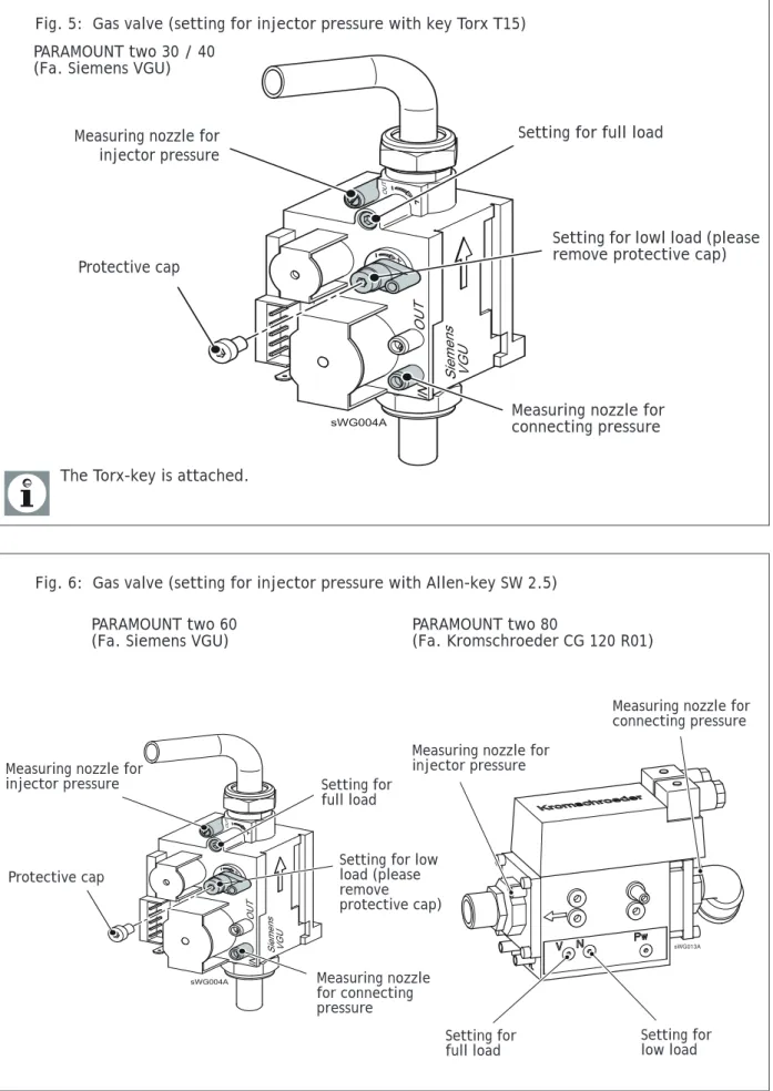
120 -393 632 .4 04.08 F h5.10 Gas valve
Fig. 5: Gas valve (setting for injector pressure with key Torx T15)
Measuring nozzle for connecting pressure
Setting for full load
Setting for lowl load (please remove protective cap) Measuring nozzle for
injector pressure
Protective cap
The Torx-key is attached. PARAMOUNT two 30 / 40 (Fa. Siemens VGU)
Fig. 6: Gas valve (setting for injector pressure with Allen-key SW 2.5)
Setting for
full load Setting for low load
Measuring nozzle for injector pressure
Measuring nozzle for connecting pressure
PARAMOUNT two 60
(Fa. Siemens VGU) PARAMOUNT two 80 (Fa. Kromschroeder CG 120 R01)
Measuring nozzle for connecting pressure
Setting for full load
Setting for low load (please remove protective cap) Measuring nozzle for
injector pressure
120
-393 632
.4 04.08 F
h
Adjusting and Checking the CO2 values
Operate the PARAMOUNT two in the controller stop mode to adjust and
check the CO2 value.
Controller Stop Mode (manual adjustment of burner load) • Press operation mode button Heating Operation for
approxima-tely 3 seconds, until the message Regulator Stop Function ON is displayed.
• Wait, until the display has reached the basic display again. Press information button. The message Regulator Stop, set
No-minal Value appears in the display. The actual modulation
de-gree will be displayed on the display.
• Press OK-button. The nominal value can now be changed and must, afterwards, to be acknowledged with the OK-button. In this way, the displayed nominal value is taken over by the con-trol.
The regulator stop function is stopped by pressing the operating
mode button Heating Operation for approximately 3 seconds,
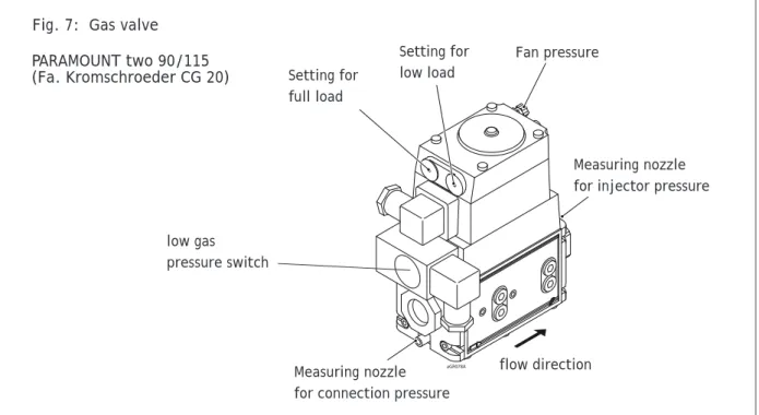
rea-ching the maximum boiler temperature or a time limit. Fig. 7: Gas valve
Measuring nozzle for connection pressure Setting for
full load
Setting for low load
Measuring nozzle for injector pressure Fan pressure flow direction low gas pressure switch PARAMOUNT two 90/115 (Fa. Kromschroeder CG 20)
Installation
120
-393 632
.4 04.08 F
h
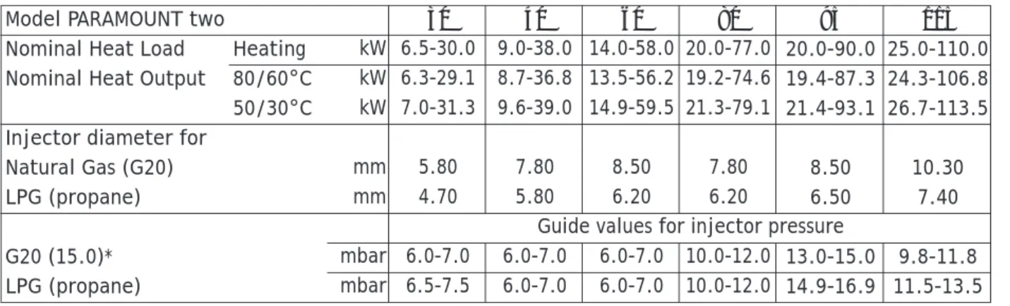
5.11 Guide Values for Injector Pressure
Guide values for gas flow, injector presure and CO2-content The listed values in tab. 9 are to be used as guide values.
5.12 Electrical connection (general)
Danger of electric shock! All electrical work in connection with the installation must only be carried out by a trained electrician! Supply power 1/N/PE
AC230V + 10% - 15%, 50 Hz max. 140 W, fuse: 6A Observe the IEE and local regulations.
The electrical connection should be made so that the polarity can-not be mixed up and is connected correctly.
Electrical Supply
A 230 V 50 Hz AC single phase electrical supply is required. The in-coming mains supply should be terminated via a double pole fused isolator to the boiler, see wiring diagram for wiring details. A fused supply is required. The boiler has a 6.3A internal fuse.
Cable Lengths
Cables for sensors of bus cables do not carry mains voltage, but low voltage. They should not be put parallel to mains wires (this may lead to disturbances) otherwise screen cable should be used. Maximum lengths of wires for all sensors:
– Copper wires up to 20 m 0.6 mm²
– Copper wires up to 80 m 1 mm²
– Copper wires up to 120 m 1.5 mm²
Strain reliefs
All electrical cables must be fed through the holes in the boiler bottom with the enclosed cable feed-throughs and fixed. Further-more, the cables have to be fixed in the strain reliefs in the control panel and connected according to the wiring diagram (fig. 8). Table 9: Guide Values for injector pressure (full
load)
Model PARAMOUNT two 30 40 60 80 95 115
Nominal Heat Load Heating kW 6.5-30.0 9.0-38.0 14.0-58.0 20.0-77.0 20.0-90.0 25.0-110.0 Nominal Heat Output 80/60°C kW 6.3-29.1 8.7-36.8 13.5-56.2 19.2-74.6 19.4-87.3 24.3-106.8 50/30°C kW 7.0-31.3 9.6-39.0 14.9-59.5 21.3-79.1 21.4-93.1 26.7-113.5 Injector diameter for
Natural Gas (G20) mm 5.80 7.80 8.50 7.80 8.50 10.30
LPG (propane) mm 4.70 5.80 6.20 6.20 6.50 7.40
Guide values for injector pressure
G20 (15.0)* mbar 6.0-7.0 6.0-7.0 6.0-7.0 10.0-12.0 13.0-15.0 9.8-11.8
LPG (propane) mbar 6.5-7.5 6.0-7.0 6.0-7.0 10.0-12.0 14.9-16.9 11.5-13.5
* Values in parenthesis = Wobbe Index WoN in kWh/m3 **At pressure at end of boiler 0 mbar, 1013 hPa, 15 °C,
120
-393 632
.4 04.08 F
h
International protection IPx4D
The screwed cable connections have to be tightened in order to meet international protection IPx4D and the specified air-tight sealing of the air chamber, so that the seal rings seal the cables.
Circulating pumps
The permissible current load per pump is IN max = 1A.
Fuses
Fuses in the Control Unit: - F1 - T 6,3 H 250 ; mains
Connecting sensors/ components
Danger of electric shock! Observe wiring diagram!
Assemble and connect accessories according to enclosed instruc-tions. Check earthing.
Outdoor temperature sensor (included with boilor)
The outside temperature sensor is enclosed in the enclosed pa-ckage. For connection see wiring diagram.
Replacing cables
All connecting cables, except for the mains connection cable, have to be replaced by POTTERON Commercial-special cables in case of replacement. When replacing the mains connection cable, only ca-bles of the types H05VV-F can be used, complying with BS 6500. Contact protection and international protection IPx4D
To ensure contact protection and international protection IPx4d, the covering parts to be screwed, have to be fastened again with the respective screws after opening the PARAMOUNT two.
Fig. 8: Strain relief
1. Insert cables and snap shut clips until they lock 2. Press down clip screws
3. Tighten clip screw with screw driver
4. Lever open the snap-mechanism with a screw driver to open the cable clips
Commissioning
120 -393 632 .4 04.08 F h6.
Commissioning
Danger! The commissioning must only be carried out by a heating specialist! The heating specialist checks tightness of the installati-on, correct function of all regulating, control and safety devices. See commissioning sheet at rear of manual!
6.1
Switching on
Danger of scalding! Hot water may exit from the blow pipe of the safety valve.
1. Switch on boiler isolator switch
2. Open gas shut-off valve
3. Open front panel cover and switch on operating switch on the front panel of the boiler
4. Select the operation mode automatic operation with the ope-ration mode button on the control unit
.
5. Set the required room temperature on the rotating knob of the control unit
6.2
Temperatures for heating and DHW
The information in the section programming for setting the tem-peratures for heating and DHW.
For DHW processing a setting onto 55°C is recommended.
You can adjust hours/minutes for DHW in time program 4. For re-asons of comfort, the time program for DHW should start one hour before time programe 1 and 2 start.
6.3
Individual time program
The boiler can be commissioned having its standard values. For adjusting parametres like individual time program, please con-sider the information given in the section Programming.
120
-393 632
.4 04.08 F
h
6.4
Programming of necessary parameters
Normally, the control parameters do not have to be modified (Ap-plication example). Only date/time and possibly the time program-mes have to be modified.
Setting of the parameters is described in the section programming.
6.5
Emergency operation (Manual operation)
Setting the emergency operation of the plant> • Press OK-button
• Select menu point maintenance/service • Set function manual operation (7140) to ""ON"
Heating circuit pumps have been switched on and mixer is set to manual opration
Using the operation mode "manual operation" you can choose a no-minal temperature value for it:
• Press button "info"
• Acknowledge selection with OK
• Adjust nominal value by using rotating knob • Acknowledge setting with OK.
See also section Explanations for setting table.
6.6
Instruction for the customer
Instruction
The customer should be instructed in the operation of the boiler and the function of the safety devices. The following should be pointed out:
– The air inlet must not be restricted;
– Flammable materials and liquids must not be stored in the vici-nity of the boiler
– The customer has to carry out the following control checks him-self>:
– Pressure check on the pressure gauge; – Check the discharge from the safety valve
– Only approved gas installers may carry out the inspection and maintenance.
Documents
– The documents, belonging to the boiler, have to be handed over with the instructions they have to be kept in the installation room of the boiler.
– Copy the commissioning sheet with confirmation and legally binding signature to the customer. All components have been in-stalled according to the instruction of the manufacturer. The whole plant complies with the relevant British Standards and current building regulations.
Operation
120-393 632 .4 04.08 F h7.
Operation
7.1
Operation elements
Fig. 9: Operating elements
Lock-out reset button Pressure gauge
Operating switch
Operating mode button heating operation Operation mode button DHW operation
Display OK-button (Acknowledgment) Information button Chimney-sweep ESC-button (Stop) Rotating knob Operating unit Boiler temperature
120-393 632
.4 04.08 F
h
7.2
Displays
Meaning of the displayed symbols
Heating at comfort nominal value Heating at reduced nominal value
Heating at frost protection nominal value Current process
Holiday function activated
Reference to heating circuit 1 or 2 Maintenance message
Fault message
INFO Information level activated
PROG Setting level activated
ECO Heating operation stopped (Automatic summer/winter
switch-over or automatic day heating limit activated)
7.3
Operation
Stop heating operation
Switching over between the operating modes for heating opration is carried out with the operating mode button heating operation. The selected setting is marked by a bar underneath the operating mode symbol.
Automatic operation – Heating operation according to time programme
– Nominal temperature values or according to time
pro-gramme
– Protection functions (plant frost protection, overheating pro-tection) activated
– Automatic summer/winter switch-over (automatic switching over between heating and summer operation from a certain outside temperature on)
– Automatic day heating limit (automatic switch from heating to summer operation, if outdoor temperature exceeds comfort no-minal value)
Fig. 10: Symbols in the display
sRE081A
Operation
120-393 632 .4 04.08 F h Continuous operation or– Heating operation without time programme – Protection functions activated
– Automatic summer/winter switch-over not activated in case of continuous operation with comfort nominal value
– Automatic day heating limit not activated in case of continuous operation with comfort nominal value
Protection operation – No heating operation
– Temperature after frost protection – Protection functions activated
– Automatic summer/winter switch-over activated – Automatic day heating limit activated
Stop DHW operation ➜ Switched on:
DHW is processed according to the selected switching program-me.
➜ Switched off:
DHW processing is deactivated. Setting nominal room value
➜ Comfort nominal value
The comfort nominal value is set directly with the rotating knob higher (+) or lower (-).
➜ Reduced nominal value
The reduced nominal value is set as follows: – Push acknowledgement button (OK) – Select heating circuit.
– Select parameter Reduced nominal value
– Set reduced nominal value with the rotating knob – Push acknowledgment button (OK) again.
Return to basic display from programming or information level by operating the operation mode button heating circuit.
Display information
Various temperatures and messages can be called up by pushing the information button<, among others:
• Room and outside temperature • Fault or service messages
When no faults occur and no service messages exist, this informa-tion is not displayed.
Fault message When the fault symbol appears in the display,a fault exists in the plant.
Further information about the fault can be called up by pressing the information button (see fault code table).
Servicing message When the servicing symbol appears in the display, a servicing message exists or the plant is in a special mode.
120-393 632
.4 04.08 F
h
By pressing the information button, further information can be called up (see servicing code table).
The maintenance message has not been activated by the setting in the factory.
Chimney-sweep function The chimney-sweep function is activated or deactivated by the chimney-sweep button . The activated special function is
dis-played by the symbol n the display.
Restore standard values
The standard values will be restored as described below: – Select level engineer and prog.-nr. 31
– Change to Yes and wait until value is switching back to No – Leave menu by pressing ESC
You can find more information for adjusting parameters in the sec-tion secsec-tion 8. „Programming”.
Programming
120 -393 632 .4 04.08 F h8.
Programming
The controller must be programmed after installation.
8.1
Programming procedure
The selection of the setting levels and menu points for end users and heating specialists is carried out by means of the following di-agram:
Fig. 11: Selection of setting levels and menu points
Setting levels: Enduser (E) Commissioning (I)
incl. enduser (E)
Engineer (F)
incl. enduser (E) and commissioning (F)
OEM
includes all other setting levels and is protected by a password.
Basic display
Press for approximately 3 s, until the display End User appears.
Menu points:
Time and date Operator section
Time prog heating circuit 1 Time prog heating circuit 2 Time program 3/HCP Time program 4/DHW Holidays heating circuit 1 Holidays heating circuit 2 Heating circuit 1 Heating circuit 2 Domestic hot water Boiler
Solar
Buffer storage tank DHW storage tank Direct DHW charging Configuration LPB Fault Maintenance/Service State
Diagnostics heat generation Diagnostics consumers
Not all menu points are visible, depending on the selection of setting level and programming! Boiler temperature
Press
Information button
120
-393 632
.4 04.08 F
h
8.2
Modification of parameters
Settings, which are not directly modified via the front panel, have to be carried out in the setting level.
The basic programming processs is depicted in the following by the setting of time and date.
Basic display:
Press .
Select the menu point time and date with .
Acknowledge selection with .
Select the menu point hours/minutes with .
Acknowledge selection with .
Carry out hour setting (e.g. 15 hours) with .
Acknowledge setting with .
Carry out minute setting (e.g. 30 minutes) with .
Boiler temperature
Operating unit
Time and date
Time and date Hours/minutes
Time and date Hours/minutes
Time and date Hours/minutes
Programming
120
-393 632
.4 04.08 F
h
The previous menu point will be called up by pressing the ESC-but-ton without taking over previously modified values.
If no settings are carried out for approximately 8 minutes, the basic display is called up without taking over previously modified values.
8.3
Setting table
• Not all parameters displayed in the display are listed in the set-ting table.
• Depending on the plant configuration, not all parameters listed in the setting table are displayed in the display.
• In order to get to the setting levels: Enduser (E), Commissioning (I) and Engineer (F), press button OK.; After this, press for ap-proximately 3 s the Information button, select the required le-vel with the rotating knob and acknowledge with the OK button.
Acknowledge setting with .
Press heating circuit operation mode but-ton to return to the basic display.
Time and date Hours/minutes
Boiler temperature
Table 10: Setting the parameters
Function Prog.-No.
Set-ting level 1 Standard value Modi-fied value Time and date
Hours/minutes 1 E 00:00 (h:min) Day/month 2 E 01.01 (day. month) Year 3 E 2004 (year) Operating unit Language 20 E English Contrast of display 25 E 162 Operation lock OFF | ON 26 F Off Programming lock OFF | ON 27 F Off
120
-393 632
.4 04.08 F
h
Operator section save basic settings
No |Yes
This parameter is only visible in the room device!
30 F No
Operator section activate basic settings
No |Yes 31 F No
Use as
Room device 1 | Room device 2 | Operating device | Service device
This parameter is only visible in the room device!
40 I Room device 1
Attribution room device 1
Heating circuit 1 | Heating circuit 1and 2
This parameter is only visible in the room device, as the operating unit in the boiler is fixed programmed for the operating device!
42 I Heating circuit 1
Operation HK2
Together with HK1 | independent 44 I Together with HK1
Operation HKP
Together with HK1 | independent 46 I Together with HK1
Effect of presence button
None | Heating circuit 1 | Heating circuit 2 | together
This parameter is only visible in the room device!
48 I none
Readjustment room sensor
This parameter is only visible in the room device!
54 F 0.0°C
Time programme heating circuit 1
Pre-selection Mo-Su
Mo-Su | Mo-Fri | Sa-Su | Mo |Tue |Wed Thu | Fri | Sa | Su
500 E Mo - Su
1st phase ON 501 E 06:00 (h/min)
1st phase OFF 502 E 22:00 (h/min)
2nd phase ON 503 E --:-- (h/min)
2nd phase OFF 504 E --:-- (h/min)
3rd phase ON 505 E --:-- (h/min)
3rd phase OFF 506 E --:-- (h/min)
Standard values
No |Yes 516 E No
Time programme
heating circuit 2 Parameter only visible, if heating circuit 2 exists!
Pre-selection Mo-Su
Mo-Su | Mo-Fri | Sa-Su | Mo |Tue |Wed Thu | Fri | Sa | Su
520 E Mo - Su
1st phase ON 521 E 06:00 (h/min)
1st phase OFF 522 E 22:00 (h/min)
Function Prog.-No.
Set-ting level 1 Standard value Modi-fied value
Programming
120 -393 632 .4 04.08 F h 2nd phase ON 523 E --:-- (h/min)2nd phase OFF 524 E --:-- (h/min)
3rd phase ON 525 E --:-- (h/min)
3rd phase OFF 526 E --:-- (h/min)
Standard values
No |Yes 536 E No
Time programme 3 / HCP
Pre-selection Mo-Su
Mo-Su | Mo-Fri | Sa-Su | Mo |Tue |Wed Thu | Fri | Sa | Su
540 E Mo - Su
1st phase ON 541 E 06:00 (h/min)
1st phase OFF 542 E 22:00 (h/min)
2nd phase ON 543 E --:-- (h/min)
2nd phase OFF 544 E --:-- (h/min)
3rd phase ON 545 E --:-- (h/min)
3rd phase OFF 546 E --:-- (h/min)
Standard values
No |Yes 556 E No
Time programme 4 / DHW
Pre-selection Mo-Su
Mo-Su | Mo-Fri | Sa-Su | Mo |Tue |Wed Thu | Fri | Sa | Su
560 E Mo - Su
1st phase ON 561 E 05:00 (h/min)
1st phase OFF 562 E 22:00 (h/min)
2nd phase ON 563 E --:-- (h/min)
2nd phase OFF 564 E --:-- (h/min)
3rd phase ON 565 E --:-- (h/min)
3rd phase OFF 566 E --:-- (h/min)
Standard values
No |Yes 576 E No
Holidays heating circuit 1
Start 642 E --.-- (day. month)
Finish 643 E --.-- (day. month)
Operation level
Frost protection | Reduced 648 E Frost Protection
Holidays heating
circuit 2 Parameter only visible, if heating circuit 2 exists!
Start 652 E --.-- (day. month)
Finish 653 E --.-- (day. month)
Operation level
Frost protection | Reduced 658 E Reduced
Heating circuit 1
Comfort nominal value 710 E 20.0°C
Reduced nominal value 712 E 18.0°C
Function Prog.-No.
Set-ting level 1 Standard value Modi-fied value
120
-393 632
.4 04.08 F
h
Frost protection nominal value 714 E 10.0°C
Nominal line gradient 720 E 3.50
Summer/winter heating limit 730 E 20°C
Room influence 750 I - - - %
Boost heating 770 F - - -°C
Quick setback
Off | Down to reduced setpoint | Down to frost prot setpoint
780 F Down to reduced
setpoint Floor curing function
Off | Functional heating | Curing heating | Functio-nal/
curing heating | Manual
850 F Off
Floor curing setp manually 851 F 25°C
Speed step design point 884 I 3017 / 20 / 30 /
30
Pump-PWM Minimum 885 I 41 / 40 / 40 / 40
%
Normal outside temperature 886 I - 20 °C
Flow nominal value Normal outside temperature 887 I 75°C
dT Spreading Normal outside temperature 894 I 20.0°C
Heating circuit 2 Parameter only visible, if heating circuit 2 exists!
Comfort nominal value 1010 E 20.0°C
Reduced nominal value 1012 E 18.0°C
Frost protection nominal value 1014 E 10.0°C
Nominal line gradient 1020 E 1.50
Summer/winter heating limit 1030 E 20°C
Room influence 1050 I - - - %
Boost heating 1070 F - - -°C
Quick setback
Off | Down to reduced setpoint | Down to frost prot setpoint
1080 F Down to reduced
setpoint
Mixing valve boost 1130 F 6°C
Floor curing function
Off | Functional heating | Curing heating | Functio-nal/
curing heating | Manual
1150 F Off
Floor curing setp manually 1151 F 25°C
Domestic hot water
Nominal value 1610 E 55°C
Reduced nominal value 1612 F 40°C
Release
24h/day | Time programmes Heating circuits | Time programme 4/TWW
1620 I Time programme
4/TWW Legionella function
Off | Periodically | Fixed weekday 1640 F Fixed weekday
Function Prog.-No.
Set-ting level 1 Standard value Modi-fied value
Programming
120
-393 632
.4 04.08 F
h
Legionella funct periodically 1641 F 3
Legionella funct weekday
Monday | Tuesday | Wednesday | Thursday | Friday | Saturday | Sunday
1642 F Sunday
Legionella funct time 1644 F :
-Legionella funct setpoint 1645 F 65°C
Legionella funct duration 1646 F
-Circulating pump release
Time programme 3/HKP | Drinking water release | Time programme 4/TWW
1660 I Drinking water
release Circulation pump cycle operation
OFF | ON 1661 I ON
Boiler
Nominal value manual operation 2214 E 60°C
Drinking water
sto-rage Parameter according to hydraulic diagram!
Flow setpoint boost 5020 F 18°C
Configuration Hydraulic scheme 5701 I 2 Heating circuit 1 OFF | ON 5710 I ON Heating circuit 2 OFF | ON 5715 I ON
Zones with feed pump
No |Yes 5761 I No
HK1with feed pump
No |Yes No
HK2 with feed pump
No |Yes No
TWW with feed pump
No |Yes No
Relay output K2
Default | Message output | Alarm output | operation message | External transformer | Heating circuit pump HK2 | Circulation pump | Gate veil function | Pump hydraulic bypass | Feed pump Q8 | Basic func-tion K2 | TWW-charging | Threshold analoguous sig-nal RelCl | Exhaust gas flap | Collector pump | Fan switch-off | Pump Q1 | DHW mixing pump Q35
5920 I Fan switch-off
Feed pump
Relay output 1 RelCl
Default | Message output | Alarm output | Operation message | External transformer | Heating circuit pump HK2 | Circulation pump | Gate veil function | Pump hydraulic bypass | Feed pump Q8 | Basic func-tion K2 | TWW-charging | Threshold analoguous sig-nal RelCl | Exhaust gas flap | Collector pump | Fan switch-off | Pump Q1 | DHW mixing pump Q35
5922 I Default
Relay output 2 RelCl
Default | Message output | Alarm output | Operation message | External transformer | Heating circuit pump HK2 | Circulation pump | Gate veil function | Pump hydraulic bypass | Feed pump Q8 | Basic func-tion K2 | TWW-charging | Threshold analoguous sig-nal RelCl | Exhaust gas flap | Collector pump | Fan switch-off | Pump Q1 | DHW mixing pump Q35
5923 I Default
Function Prog.-No.
Set-ting level 1 Standard value Modi-fied value
120
-393 632
.4 04.08 F
h
Relay output 3 RelCl
Default | Message output | Alarm output | Omessage | External transformer | Heating circuit pump HK2 | Cir-culation pump | Gate veil function | Pump hydraulic bypass | Feed pump Q8 | Basic function K2 | TWW-charging | Threshold analoguous signal RelCl | Exhaust gas flap | Collector pump | Fan switch-off | Pump Q1 | DHW mixing pump Q35
5924 I Default
Relay output 1 SolCl
Default | Message output | Alarm output | Operation message | External transformer | Heating circuit pump HK2 | Circulation pump | Gate veil function | Pump hydraulic bypass | Feed pump Q8 | Basic func-tion K2 | TWW-charging | Threshold analoguous sig-nal RelCl | Exhaust gas flap | Collector pump | Fan switch-off | Pump Q1 | DHW mixing pump Q35
5926 I Default
Relay output 2 SolCl
Default | Message output | Alarm output | Operation message | External transformer | Heating circuit pump HK2 | Circulation pump | Gate veil function | Pump hydraulic bypass | Feed pump Q8 | Basic func-tion K2 | TWW-charging | Threshold analoguous sig-nal RelCl | Exhaust gas flap | Collector pump | Fan switch-off | Pump Q1 | DHW mixing pump Q35
5927 I Default
Relay output 3 SolCl
Default | Message output | Alarm output | Operation message | External transformer | Heating circuit pump HK2 | Circulation pump | Gate veil function | Pump hydraulic bypass | Feed pump Q8 | Basic func-tion K2 | TWW-charging | Threshold analoguous sig-nal RelCl | Exhaust gas flap | Collector pump | Fan switch-off | Pump Q1 | DHW mixing pump Q35
5928 I Default
Function input H1
No | Modem function | Modem function inversely | Gate veil function | Feed-back Exhaust gas flap| gene-rator lock | Generaror lock inverse
5950 I none Modem function BA-switch-over HK’s + TWW | BA-switch-over HK’s | BA-switch-over HK 1| BA-switch-over HK 2 5957 I BA-switch-over HK’s + TWW Configuration Room thermostat 1
None | Room thermostat | timer Room level | timer heating request | timer TWW level
5970 I Room thermostat
Configuration Room thermostat 2
None | Room thermostat | timer Room level | timer heating request | timer TWW level
5971 I none
Function input RelCl
No | Modem function | Modem function inverse | Gate veil function | Nominal value specification | Power specification | Sensor hydraulic bypass | Feed-back exhaust gas flap | generator lock | generator lock inverse | Generator lock sensor
5973 I none
Ext. Flow nominal value maximum 5975 I 100 °C
Ext. Power specification threshold 5976 I 5 %
Function input SolCl
No | collector sensors 5978 I none
Time constant building 6110 I 10 h
ConfigContr1.0 6240 F 0
ConfigContr1.1 F 0
ConfigContr1.4 F 1
Function Prog.-No.
Set-ting level 1 Standard value Modi-fied value
Programming
120 -393 632 .4 04.08 F h ConfigContr1.7 F 0 LPB Equipment address 6600 I 1 Fault SW Diagnosis code 6705 EFA phase disturbance position E
Maintenance / Service Message 7001 E 0 Acknowledgement message 7010 E 0 Manual control OFF | ON 7140 E Off State
Status heating circuit 1 8000 I
Status heating circuit 2 8001 I
Status DHW 8003 I
Status boiler 8005 I
Status solar 8007 I
Diagnosis genera-tor
Boiler temperature/Boiler nominal value 8310 I
Boiler return temperature 8314 I
Operation display FA 8328 I
Ionization current 8329 I
Operating hours burner 8336 I
Start counter burner 8337 I
Operating hours heating operation 8338 I
Operating hours TWW 8339 I
Operating hours zones 8340 I
Collector temperature 1 8510 I
Operating hours solar gains 8530 E
Diagnosis consumer
Outside temperature 8700 I
Outside temperature decreased 8703 I
Outside temperature mixed 8704 I
Room temperature 1 8740 I
Room nominal value 1 I
Flow temperature 1 8743 I
Flow nominal value 1 I
Room temperature 2 8770 I
Room nominal value 2 I
Flow temperature 2 8773 I
Function Prog.-No.
Set-ting level 1 Standard value Modi-fied value
120
-393 632
.4 04.08 F
h
Parameters with the program numbers 1-54 are individual parame-ters of the operating unit and the room device and may, therefore, be set differently on both devices. All parameters from program number 500 onwards are stored on the controller and, therefore, identical. The value modified last, is the valid value.
Flow nominal value 2 I
DHW temperature 1 8830 I
DHW nominal value I
DHW temperature 2 8832 I
DHW charging temp 8836 I
Buffer temp 1 8980 I
Information values The display of the information values depends on the operation status!
Fault message E
SW Diagnosis code E
Message E
State manual control E
Controller stop nominal value E
Screed nominal value actual E
Screed day actual E
Room temperature E
Room temperature minimum E
Room temperature maximum E
Boiler temperature E
Drinking water temperature 1 E
Collector temperature 1 E
Status boiler E
Status solar E
Status DHW E
Status heating circuit 1 E
Status heating circuit 2 E
Outside temperature E
Buffer temp 1 E
Room temperature 1 E
Room nominal value 1 E
Room temperature 2 E
Room nominal value 2 E
Operation display FA E
1. E = Enduser; I = Commisioning; F = Engineer
Function Prog.-No.
Set-ting level 1 Standard value Modi-fied value
Programming
120
-393 632
.4 04.08 F
h
8.4
Explanations for setting table
Time and date
Time and date (1 to 3) The control has a year clock with setting possibilities for time, day/month and year. Time and date muste be correctly set, so that the heating programs can operate to previously carried out pro-gramming.
Operating unit Language
(20)
The language of the menu guidance can be modified under pro-gramme number 20.
Operation lock (26)
If this function is activated the following operating elements are locked:
– Operating mode buttons for heating and DHW mode – Control knob (comfort-setpoint room temperature) – Presence button (only room device)
Programming lock (27)
If programming lock is activated, the parameters can be displayed, but not changed.
• Temporary unlocking:
Press the OK- and the ESC-button simultaneously for at least 3 sec. The lock will be re-activated after leaving the setting level. • Permanent unlocking:
At first temporary unlocking, then prog. no. 27 to "Off". Save basic settings
(30) The data of the control will be written into the room unit (only available for room unit).
Caution! The data of the room unit will be overwritten!
With this, the individual programming of the control in the room unit can be ensured.
Activate basic settings
(31) The data of the operating unit or room unit will be written into the control.
Caution! The data of the control will be overwritten! The factory settings are stored in the operating unit.
– Activation of the prog. no. 31 at the operating unit: The control will be reset to the factory settings.
– Activation of the prog. no. 31 at the room unit: The individual programming of the room unit will be written into the control. Used as
(40) Selection of the operating unit. Depending on the selected opera-ting unit, further settings are necessary, which are described under the following program numbers.
Assignment device 1 (42)
If the setting Room unit 1 (prog. no. 40) has been selected at the room unit, it must be set under program number 42, if the room unit will be attributed to heating circuit 1 or both heating circuits. Operation HC2/HCP
(44, 46)
When selecting Room unit 1 or Operator unit (prog. no. 40), it must be set under prog. no. 44 or 46, if the heating circuits HC2 and HCP have to be operated together with heating circuit 1 or in-dependent from heating circuit 1 by the operator unit.
Action occupancy button (48)
The effect of the presence button on the heating circuits has to be set under prog. no. 48.
120 -393 632 .4 04.08 F h Re-adjustment room sensor (54)
The temperature display of the value, transmitted by the room sensor, can be corrected under prog. no. 54.
Time programs Preselection
(500, 520, 540, 560) Before a time programme is set, the individual days (Mo, Tu, We, etc.) or day groups (Mo-Su, Mo-Fr, Sa-Su) have to be selected, at which the time programme has to be activated.
When the set time of a day group is changed, this will automatical-ly be taken over for all 3 on/off phases in this day group.
Heating phases
(501 to 506, 521 to 526, 541 to 546 and 561 to 566)
Up to three heating phases may be set per heating circuit, which will be activated on the days, set under the preselection (prog.-no. 500, 520, 540, 560). In the heating phases, it will be heated at the set comfort setpoint. Outside the heating phases, it will be he-ated at the reduced setpoint.
The time programs are only activated in the operation mode “Au-tomatic“.
Default values
(516, 536, 556, 576)
Setting of the default values given in the setting table Holiday programs
The heating circuits may be set to a selectable operation level with the holiday programme during a certain holiday period.
Start (642, 652)
Entering the holiday start End
(643, 653) Input of holiday end
Operation level
(648, 658) Selection of the operation level (reduced setpoint or frost protec-tion) for the holiday program
The holiday programmes are only activated in the operation mode “ Automatic “.
Heating circuits Comfort setpoint
(710, 1010)
Setting the comfort setpoint Reduced setpoint
(712, 1012) Setting the reduced setpoint to reduce the room temperature du-ring secondary usage times (e.g. at night or when absent). Frost protection setpoint
(714, 1014) Setting the frost setpoint, so that a too big decrease of the room temperature is prevented. Heating curve slope
(720, 1020) The flow temperature nominal value is formed with the help of the heating curve, which is used to control the flow temperature de-pending on the weather.
Programming
120
-393 632
.4 04.08 F
h
Determination of the heating curve slope
Enter lowest calculated outside temperature according to climate zone into the diagram (see fig. 12), e.g. vertical line at -10°C. En-ter maximum flow temperature of the heating circuit (e.g. hori-zontal line at 60°C).
The intersecting point gives the value for the heating curve slope.
Summer/winter heating limit
(730, 1030)
The heating will be switched over to summer or winter operation at the temperature set here, whereby the reduced outside tempe-rature becomes the reference tempetempe-rature (prog. no. 8703). - - - °C: deactive
Room influence (750, 1050)
In the case of room influence, the deviations from the room tem-perature setpoint is recorded by a room sensor and taken into ac-count for the temperature control.
A room sensor must be connected. The value for the room influ-ence mut be between 1% and 99%. Should there be radiator valves in the leading room (assembly location of the room sensor), these have to be fully opened.
Setting for weather compensation with room influence: 1% - 99% Setting for pure weather compensation: ---%
Setting for pure room compensation: 100% Boost heating
(770, 1070) In case of a change from reduced to comfort setpoint, heating is carried out by boost heating at an increased flow temperature un-til reaching the comfort setpoint, so that the room is heated up quickly.
Quick setback
(780, 1080) If this function is activated the heating pump will be switched off. When reaching the setpoint, the heating pump will be re-started and the temperature controlled to the reduced setpoint or the frost protection setpoint. The duration of the quick setback de-pends on the outside temperature, time constant building (prog. Fig. 12: Heating curve diagram.
4 3,5 3 2,75 2,5 2,25 2 1,75 1,5 1,25 1 0,75 0,5 0,25 20 10 0 -10 -20 -30 °C 30 40 50 60 70 30 80 90 100 °C Flo w tempera ture Outside temperature
![Table 5: Resistance values for flow sensor, DHW sensor, return sensor, sensor B4 Temperature [°C] Resistance [ Ω ] 0 32555 5 25339 10 19873 15 15699 20 12488 25 10000 30 8059 35 6535 40 5330 45 4372 50 3605 55 2989 60 2490 65 2084 70 1753 75 1481 80 1256](https://thumb-us.123doks.com/thumbv2/123dok_us/9702002.2459523/15.892.316.681.542.993/table-resistance-values-sensor-sensor-return-temperature-resistance.webp)