Chapter 6. Virtual and Rapid Prototyping
Design evaluation of virtual clay models using selective
laser sintering
Frank-L. Krause
Yasmina Bock and Stefan Dreher
Fraunhofer Institut fur Produktionsanlagen und Konstruktionstechnik Key words: Voxel-based modelling, selective laser sintering
Abstract: Subject of this research is the complete integration of the styling process into the computer-aided product development and thus to optimise the process chain design and to close media gaps. A new voxel-based 3D modeller is developed, the Virtual Clay Modelling System (VCM) (I), allowing the stylist to work with the virtual clay model in strong analogy to conventional clay modelling, supported by advanced VR-techniques. The VCM provides a STL- and CLI -interface, which serve as input for the selective laser sintering (SLS) process.
1 INTRODUCTION
To achieve an integration of the styling process Computer-Aided Industrial Design (CAlD) systems have to be developed which effectively support the designer and allow to replace conventional styling methods. The Virtual Clay Modelling System will speed up development times in industrial design and leads to a better exploitation of the creative potential of the stylist. The integration of rapid prototyping processes provides the possibility of a fast design evaluation. The selective laser sintering process is unique in its capability of builing complex geometry using a huge variety of materials. Today, the STL format is used widely as input format for rapid prototyping machines. But standard slicing algorithms are not able to meet all requirements. This problem can be eliminated by using a system for technological process planning. The output of this system is then used as an optimized build-profile for the machine.
2 VIRTUAL CLAY MODELLING
The creative and intuitive working style during the early phase of design is not sufficiently supported by existing CAlD systems. The essential reason for this is to be seen in the adaptation of the abstract geometrical free-form surface modelling processes of CAD systems to the design process in such way as not to allow for a sketch-like design activity. The suitability of processes for design is to be judged considering the requirements of greater flexibility, a greater degree of interactivity and the transparent realisation of modifications to the model based on modelling operations.
The implemented prototype of a Virtual Clay Modelling System allows the generation of design models in analogy to conventional clay modelling providing adequate support for the designer without restrictions on his expressive work.
2.1 Principle of Virtual Clay Modelling
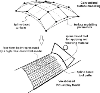
The Virtual Clay Modelling System is based on computer-internal tools which can be applied to the virtual clay. In analogy to conventional clay modelling the designer can generate
arbitrarily shaped models by simply adding or removing "material" (fig. 1). This Cut&Paste is done with the graphical representation of spline-based modelling tools the stylist directly manipulates using a mouse, space-mouse or tracking system and that take the forms of plane rakes, templates or true sweeps. Compared to conventional styling systems a new paradigm has been developed operating on a discrete model using mathematically exact represented modelling tools using rational B-splines and therefore without the required knowledge of spline-based surfaces. The change in the modelling paradigm results in the provision of complex shaped tools instead of elementary parameters for shape modification as in the spline modelling paradigm
Spline-based
surfaces
Free-form body represented by a high-resolution voxel-model Conventional surface modelling Surface modelling parameters. Spline-based tool for applying and
Spline-based tool paths Voxel·based
Virtual Clay Model
Figure 1. Principle of virtual clay modeling
Figure 2. Interactive tool editor
2.2 Design process
The realisation of the modelling operations is based on elementary Boolean operations 202
which are performed on the virtual clay model represented as a compressed voxel1 model with
a high degree of resolution. For model visualisation an extended Marching Cubes Algorithm (4) is applied that reproduces the exact positions of the polygons surrounding the volumetric mode1.3).
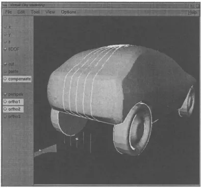
Figure 3. Highlight lines on an imported model
As in the real-world process, flexibly controllable linear light source provide the ability to perform a qualitative evaluation of the sketched form. To support the stylist while modelling, three methods for free-form surface evaluation have been implemented:
• Highlight-lines by Beier (5) • Reflection lines
• Iso-photes, indicating areas of the same light intensity
Discontinuities of the highlight or reflection lines indicate a discontinuity of the surfaces evaluated.
When modelling is finished, the voxel-based model is converted to a NURBS2 model
which enables the export to standard CAD/CAM systems. The conversion of the voxel model into a NURBS model is based on the facets generated by the Marching Cubes Algorithm.
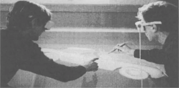
The interactive styling process is supported by a three-dimensional perception of the model, enabled by stereoscopic viewing in conjunction with so called shutter glasses. The use of a Responsive Workbench
™
beside the desktop VR solution allows highly intuitive and interactive design in a real world like surrounding. The stylist can interact with the virtual clay model, his view point of the model is tracked to provide the correct perspective.I voxel = volume element
2.3 Model evaluation using physical models
The volumetric modelling system provides a direct link to rapid prototyping processes and thus a possibility to generate and evaluate physical models at an early stage. The VCM system offers the possibility to generate Open Inventor files which is used for the graphical representation ofthe model. The triangulated representation can be directly converted to STL-format. Furthermore the VCM system offers direct slicing of the model referring to the voxel data structure.
Figure 4. VCM and Responsive Workbench™
3
BUILDING A PROCESS CHAIN INCLUDING
SELECTIVE LASER SINTERING
As this research aims at the complete integration of the styling process into a computer-aided process chain, an easy-to-use method had to be developed to generate physical models for design evaluation without an extra demand for knowledge about the rapid prototyping (RP) process. To enable communication between design and RP, the user interface of the VCM system enables the stylist to choose between several output formats.
4 SELECTIVE LASER SINTERING
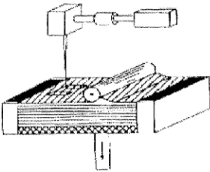
The RP method 'Selective Laser Sintering' is designed to build parts of high complexity, high grade of undercuts and thin walls. It works in principle with any kind of thermoplastic powder, which is melted by a laser beam, as shown in figure 5. For design evaluation, there is an assortment of several polyamide materials which differ in surface quality, hardness and expansion coefficient. Surfaces are grindable. For color impression, a lacquering has to be applied.
4.1 TECHNOLOGICAL PROCESS PLANNING
The programming of Rapid Prototyping devices is done at present by device dependent software using an STL interface. This conducts, due to insufficient description of requirements, to difficulties with data preparation and manufacturing of prototypes. Available systems offer an insufficient functionality for the adaptation of process parameters to prototype requirements. For this reason a configurable software component for process-oriented planning and NC-data generation has been developed. The use of the planning module reduces build time while prototype accuracy can be increased.
The planning module is applicable for various Rapid Prototyping techniques. The main techniques are Stereolithography and Selective Laser Sintering.
Existing functionality supports • workpiece positioning and grouping
• decomposition of a CAD model into critical workpiece ranges • shape-referred definition of technological parameters • generation of layermodels
• generation ofNC-scan pathes.
Figure 5. Function principle of SLS
Visualization emphasizes speed and surface finish over tolerances or part strength. The goal is to produce a model that can quickly be manufactured, reviewed and passed around to discuss potential changes. As a result, all process parameters with a substantial influence on surface quality and speed have to be optimized for model evaluation. To reach this goal, major parameters have to be isolated. One of these is the overall sum of cross sections, which is directly related to build time. Reducing the scanned surface leads to significant reduction of time and cost of the parts. Consequently, parts are hollowed out in case that functionality is not tested. First task of the planning system is determination of build orientation and grouping of work pieces in the workroom. As RP-devices build up the parts in a layerwise structure, the characteristics of builded parts show different surface roughness in x, y and z-direction. So the system analyses surface structures in order to achieve minimal stairstep errors.
In subsequent steps the user defines interactively device-specific parameters like laser power or pro- cess temperature. A process oriented database stores best parameter values as experience shows and gives recommendations. The user just accepts these values in case he is unsure about the correct inputs.
4.2 ADAPTIVE SLICING
Considering build time, an important variable is layer thickness. Imagine that double layer thickness leads to nearly half build time and you would have to pay 25 to 35 percent less for the prototype.
To reach this goal, the component subdivides the workpiece into height ranges with constant layer thickness under the aspect of precision demands, controlled by the user. When intricate geometry is detected, layer thickness will be adapted conside- ring requested surface roughness, as Figure 6 shows.
5 EXAMPLE
Figure 7 and Figure 8 show the verified way from a simple virtual clay model to the physical model generated by selective laser sintering.
Figure 6. Simplified example of segment based adaptive slicing
Figure 7. Voxel-based car model
6
SUMMARY
The Virtual Clay Modelling system is a highly interactive styling tool for conceptual styling with strong analogies to conventional methods of clay modelling providing a link to rapid prototyping processes due to the nature of the discrete voxel-based model. The given voxel representation and its triangle based visualisation is used for the generation of STL- and CLI-files which serve as input for the selective laser sintering process. The presented approach allows working on a unified database of discrete geometry for the phases of design,
process planning and process verification, avoiding tedious steps along the process chain which includes sculptured surface reconstruction.
Future developments of the virtual clay modelling system will concentrate on the development of deformable tools in order to achieve a large variety of surfaces to be modelled as well as the integration of a two-handed manipulation of the virtual clay model including a force feedback device.
Figure 8. Carbody generated by selective laser sintering.
REFERENCES
1 Liiddemann, 1., (1996), Virtuelle Tonmodellierung, Dissertation, Technical University Berlin 2 Krause, F.-L., Liiddemann, 1.., (1996), Virtual Clay Modelling, IFfP WG5.2 Workshop, Airlie, 19-23
May 1996
3 Tovey, M., (1994), Form Creation Techniques for Automotive CAD, Design Studies, 15(1), pp.
85-114
4 Lorensen, W., Cline, H., (1987), Marching cubes: a high resolution 3D surface construction algorithm, ACM Computer Graphics, 21(4), pp. 163-170
5 Beier, K.-P., Chen, Y, (1994), Highlight-line Algorithm for Realtime Surface-Quality Assessment,
Computer-Aided Design, 26(4), pp. 268-275
6 Krause, F.-L. ; Ciesla, M.; Klocke, F; Wirtz, H.; Ulbrich, A.: Improving Rapid Prototyping Processing Speeds by Adaptive Slicing. Dr. P. M. Dickens (Ed.), Proc. of the 6th European Conference on Rapid
Prototyping and Manufacturing, Nottingham, 1.-3. July 1997, S. 31-36
7 Krause, F.-L.; Ciesla, M.; Stiel, Ch; Ulbrich, A.: Enhanced Rapid Prototyping for Faster Product Development Processes. Annals of the CIRP Vol. 46/1/1997, Hallwag Ltd. , Bern, S. 93-963 Kruth, 1.P .. Material increase manufacturing by rapid prototyping techniques. Ann. CIRP, 1991, 40(2), 603-614.