THE EFFECTS OF PITCH AND FLUTING ON INSERTION
TORQUE AND PULLOUT STRENGTH OF
MINISCREW IMPLANTS
Christine L. Brinley, B.S., D.M.D.
An Abstract Presented to the Faculty of the Graduate School of Saint Louis University in Partial Fulfillment
of the Requirements for the Degree of Master of Science in Dentistry
ABSTRACT
Purpose: This study was designed to isolate two design characteristics of miniscrew implants (MSIs), pitch and fluting, and to determine their effects on primary
stability. Methods: Maximum placement torque and pullout strength of MSIs specifically fabricated for this
experiment were compared to a control MSI using synthetic and cadaver bone models. The first experimental condition compared MSIs with 0.75 mm and a 1.25 mm pitch to a control MSI with a 1.0 mm pitch. The second experimental condition compared MSIs with 3 longitudinal flutes to a control
without flutes. A total of 60 MSIs (15 of each design) were placed in the synthetic bone model; a split-mouth cadaver model was used to compare the three experimental designs (15 of each design) against the control MSIs (total of 45 MSIs). Maximum placement torque was measured as MSIs were inserted with intermittent rotation. To test pull-out strength, a vertical force was applied until failure. Results: The synthetic bone model showed that placement torque and pull-out strength were higher for the 0.75 pitch MSIs than the 1.0 mm and 1.25 mm pitch MSIs, but difference were significant (p<.05)only for pull-out strength. The cadaver model showed no significant differences in
2
placement torque or pullout strength associated with pitch. In both the synthetic and cadaver bone model, MSIs with flutes had significantly (p<.05) higher placement torque and pullout strength. Spearman correlations between
placement torque and pullout strength were statistically significant both in the synthetic (r=.502) and cadaver (r=.504) bone models. Conclusion: Pitch and flutes affect the primary stability of MSIs. Within limits, decreasing MSI pitch increases pullout strength and fluting increases both placement torque and pullout strength.
THE EFFECTS OF PITCH AND FLUTING ON INSERTION
TORQUE AND PULLOUT STRENGTH OF
MINISCREW IMPLANTS
Christine L. Brinley, B.S., D.M.D.
A Thesis Presented to the Faculty of the Graduate School of Saint Louis University in Partial Fulfillment
of the Requirements for the Degree of Master of Science in Dentistry
i
COMMITTEE IN CHARGE OF CANDIDACY: Adjunct Professor Peter H. Buschang,
Chairperson and Advisor Professor Rolf G. Behrents
Associate Professor Sridhar Condoor Assistant Professor Ki Beom Kim
DEDICATION
To my best friend and husband, Michal, for his tremendous support and understanding during a very difficult time.
iii
ACKNOWLEDGEMENTS
I would like to acknowledge the following individuals: Dr. Peter Buschang for chairing my thesis committee. Thank you for your guidance, patience, insights and time. You have gone “over and beyond” what I could have ever expected and I will never forget your kindness.
Dr. Rolf Behrents for serving on my committee. I truly appreciate your assistance with the writing of my thesis.
Dr. Ki Boem Kim for serving on my committee. I appreciate all of your advice throughout my thesis and orthodontic education.
Dr. Sridhar Condoor for serving on my committee. This project would not have been possible without your insight and suggestions.
Drs. Cooper and Tolbert for assistance with the cadaver specimens.
Karen Fete for help both mental and physical in the cadaver lab. I would have not been able to do it without you there.
Joe Tricamo for help with the set up and manufacturing of all devices needed for testing.
TABLE OF CONTENTS
List of Tables...vi
List of Figures...vii
Chapter 1: Introduction...1
Chapter 2: Review of the Literature Implant Stability...5 Primary Stability...5 Secondary Stability...7 Terminology...8 Design Terminology...10 Biomechanical Terminology...12
Determinants of Primary Stability...14
Placement Torque...16
Pullout Strength...18
Combination Testing...20
Factors Affecting Primary Stability...22
Bone...23
Bone Density...23
Cortical Thickness...25
MSI to Bone Interaction...26
Bone Material Properties...28
Screw-Type Implant Design Character..29
Length...30 Diameter...31 Thread Depth...32 Thread Design...33 Self-Drilling/Self-Tapping...35 Taper...38 Multiple Threads...39 Pitch...40 Flutes...42 Purpose...44 References Cited...45
Chapter 3: Journal Article Abstract...51
Introduction...53
Materials and Methods...56
Miniscrew Implants...56
Experimental Designs...56
v
Testing Methods...58
Synthetic Bone Model...59
Cadaver Bone Model...59
Mechanical Testing...60
Placement Torque...61
Pullout Strength...61
Statistical Analysis...62
Results...62
Synthetic Bone Model...62
Pitch...62
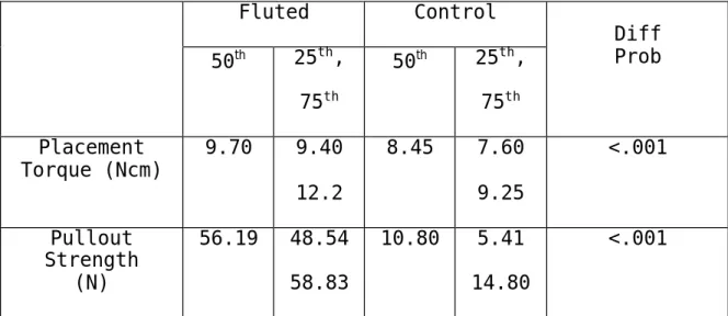
Fluted...65
Cadaver Bone Model...67
Pitch...67 Fluted...71 Discussion...74 Conclusions...77 References Cited...78 Vita Auctoris...82
LIST OF TABLES
Table 2.1: Design Characteristics of a Sample of
Commercially Available Miniscrew Implants...9 Table 2.2: Placement Torque Values of Various Screw-Type Implants...18 Table 3.1: Median, 25th, and 75th Quartile for Placement
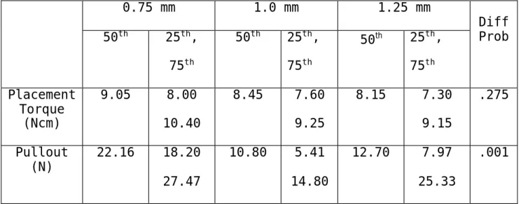
Torque and Pullout Testing of MSIs with Pitch Variation in a Synthetic Model...63 Table 3.2: Median, 25th, and 75th Quartile for Placement
Torque and Pullout Testing of MSIs with and without Fluting in a Synthetic Model...66 Table 3.3: Torque and Pullout Comparisons of a 0.75 mm and
a 1.0 mm Pitch MSI in a Cadaver Model...68 Table 3.4: Torque and Pullout Comparisons of a 1.0 mm and a 1.25 mm Pitch MSI in a Cadaver Model...70 Table 3.5: Mean and Standard Deviation for Placement Torque
and Pullout Testing of MSIs with and without Fluting in a Cadaver Model...72
vii
LIST OF FIGURES
Figure 1: MSI Length...10
Figure 2: Outer and Inner Diameters and Pitch...10
Figure 3: Symmetric Thread Design...11
Figure 4: Asymmetric Thread Design...11
Figure 5: Stress-Strain Curve...13
Figure 6: A. 0.75 mm Pitch Experimental MSI, B. 1.0 mm Pitch Control MSI, C. 1.25 mm Pitch Experimental MSI...57
Figure 7: Fluted MSI...58
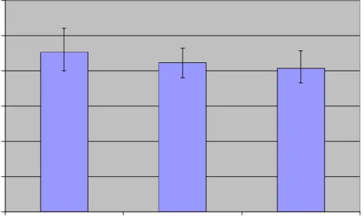
Figure 8: Median Placement Torque of 0.75 mm, 1.0 mm (Control), and 1.25 mm Pitch MSIs in Synthetic Bone with Error Bars Representing the 25th and 75th Quartiles...64
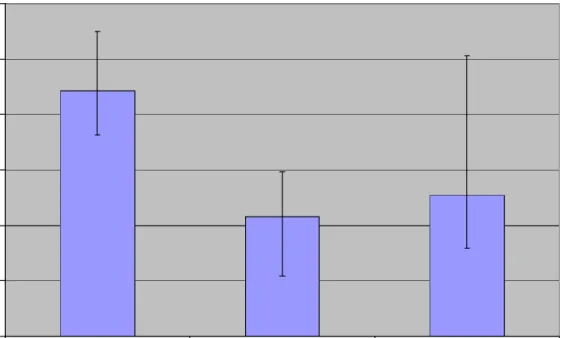
Figure 9: Median Pullout Strength of 0.75 mm, 1.0 mm (Control), and 1.25 mm Pitch MSIs in Synthetic Bone with Error Bars Representing the 25th and 75th Quartiles...65
Figure 10: Median Placement Torque of Fluted and Control MSIs in Synthetic Bone with Error Bars Representing the 25th and 75th Quartiles...66
Figure 11: Median Pullout Strength of Fluted and Control MSIs in Synthetic Bone with Error Bars Representing the 25th and 75th Quartiles...67
Figure 12: Median Placement Torque of 0.75 mm and 1.0 mm (Control) Pitch MSIs in Cadaver Bone with Error Bars Representing the 25th and 75th Quartiles...68
Figure 13: Median Pullout Strength of 0.75 mm and
1.0 mm (Control) Pitch MSIs in Cadaver Bone with Error Bars Representing the 25th and 75th Quartiles...69
Figure 14: Median Placement Torque of 1.0 mm (Control) and 1.25 mm Pitch MSIs in Cadaver Bone with Error Bars Representing the 25th and 75th Quartiles...70
Figure 15: Median Pullout Strength of 1.0 mm (Control) and 1.25 mm Pitch MSIs in Cadaver Bone with Error Bars Representing the 25th and 75th Quartiles...71 Figure 16: Median Placement Torque of Fluted and
Control MSIs in Cadaver Bone with Error Bars Representing the 25th and 75th
Quartiles...72 Figure 17: Median Pullout Strength of Fluted and Control MSIs in Cadaver Bone with Error Bars Representing the 25th and 75th
Quartiles...73
1
CHAPTER 1: INTRODUCTION
Newton’s 3rd Law states that every action has an equal and opposite reaction. Orthodontic practice is subject to the effects of this law particularly whenever teeth are used as anchorage for moving other teeth. Unfortunately it is often the case in orthodontics that the movement of some teeth is desired while the reciprocal movement of other teeth is not (i.e., anchorage). A majority of the time this results in a compromise in treatment because absolute
anchorage is, for the most part, not possible when using teeth as anchors. Extra oral devices have also been used as anchorage, but they are dependant upon patient compliance, and as a result, anchorage preservation varies and is
outside the control of the practitioner.
Miniscrew implants have made absolute anchorage a possibility. They allow the application of force to be controlled by the operator and provide an excellent alternative when traditional orthodontic anchorage is impossible, unattainable, or impractical.1 According to contemporary procedures small titanium miniscrews can be placed at various locations within the oral cavity to serve as anchorage and facilitate controlled tooth movement. The
benefits that miniscrew implants offer orthodontics have led to a rapid rise in their popularity.
Osseous screw-type implants have been studied with regards to both medical and dental applications. The use of bone screws for health-related purposes emerged during the mid-nineteenth century with the work of Cucel and Rigaud.2,3 The orthodontic literature first mentioned the use of screw type implants in 1945 in the work of Gainsforth and Higley,4 but clinical use did not gain popularity until recent
years. Because of the rather new evolution of miniscrews and miniscrew mechanics, investigators have not yet had time to thoroughly investigate the engineering principles of miniscrew design. Although a fair amount of literature exists in orthopedics and prosthetics, the findings in those areas do not always apply to orthodontics due to the very different applications and force levels involved. Disciplines other than orthodontics use much larger screw-type implants which need to withstand the heavier force loads and fracture produced by chewing.
The orthopedic and prosthetic literature has
extensively examined bone properties,5-7stability testing,8-10 screw design characteristics,11,12 insertion torque,8,12-15 and pullout strength.15-17 Orthodontic studies have touched upon the effects of miniscrew implant(MSI)diameter,18-20 length,20
3
placement method,19,20 insertion torque,18,21 and pullout strength.18 However, most of the orthodontic literature consists of case studies and force application research. There has been little attention paid to miniscrew implant design and its effect on stability.
Existing miniscrew designs are relatively similar and have remained basically unchanged since their introduction. New designs may lead to more creative anchorage
possibilities. For instance, present MSIs must maintain a minimum diameter due to the risk of MSI fracture during torsion. Maximizing stability while minimizing placement torque could allow for smaller MSIs, which could
potentially have more clinical uses. Lower placement torque could also minimize osseous trauma and lead to an increased stability. Before such development occurs, however, some basic questions regarding the relationship between MSI design and stability have yet to be answered. For example, which design characteristics influence placement torque and/or stability? Are there design possibilities yet to be introduced that could improve on the basic designs
presently available? Is there a relationship between MSI placement torque and primary stability?
The purpose of the present study is to provide information about miniscrew implant design that might
provide a foundation for the development of improved MSIs. This investigation will attempt to isolate one design
characteristic, while keeping all other parameters the same, to determine the qualities of any given design characteristic. To date, there have been no carefully crafted studies designed in this manner to evaluate
miniscrew implants used for orthodontic purposes. The goal is to systematically evaluate the effects that MSI pitch and fluting have on insertion torque and pullout strength. The following hypotheses will be tested:
1) There are no differences in insertion torque and pullout strength between MSIs with 0.75 mm, 1.00 mm and 1.25 mm pitch.
2) There is no difference in insertion torque and pullout strength between MSIs with and without flutes.
3) There is no relationship between MSI insertion torque and pullout strength.
5
CHAPTER 2: REVIEW OF THE LITERATURE
IMPLANT STABILITY
Implant stability at the time of placement and
throughout implant use is critical to success. Implants for various medical and dental uses are anchored to bone by basic mechanisms such as mechanical interlocking between the bone and the implant or soft tissue attachment. Failure of these mechanisms could be due to a number of factors including design, adverse host response, poor placement technique, or excessive loading.22 Implant stability can be classified as either primary or secondary based upon timing and bone response. Primary stability is most critical
during the early phases of miniscrew mechanics, while secondary stability becomes increasingly important as treatment progresses.
PRIMARY STABILITY
Primary stability refers to the lack of miniscrew movement at the time of initial placement. This type of
stability is considered critical in orthodontics because it allows for immediate loading.23 A lack of primary stability frequently leads to miniscrew mobility and subsequent
loss.24 It is a mechanical phenomenon thought to be a
function of the local bone quality and quantity, design of the implant, and placement technique.9 These three factors significantly influence the two major determinants of
primary implant stability: bone-to-implant contact and the compressive stresses at the bone to implant interface.9
Bone-to-implant contact has been demonstrated to be greater in dense cortical bone than in trabecular bone and better stability has been reported for implants placed in dense bone areas than in less dense areas.9 Also, there is a marked compression of local bone upon implant insertion
resulting in circumferential hoop stresses. Hoop stresses are compressive stresses generated in the bone around the implant threads that help to enhance primary stability. However, when hoop stresses are too high they can produce local ischemia and bone necrosis.9 Alternately, compressive stresses that are too low will offer very little primary stability. For optimal stability, implants should be placed in cortical bone with compressive stresses that are neither too high or too low.21
7
SECONDARY STABILITY
Bone regeneration and remodeling following implant placement results in an increase in stability referred to as secondary stability. Primary stability and secondary stability are related in that poor primary stability has a detrimental effect on subsequent secondary stability.
Limited areas of contact between the miniscrew and bone at insertion may permit micromovement which could lead to bone resorption and the formation of a fibrous capsule resulting in clinical failure.25-27 Osseous trauma and overload during miniscrew use or placement can necessitate healing and the formation of woven bone. Woven bone is part of the normal healing process, but it is poorly organized, which makes its strength too low to support loading.28 To maximize
implant retention, care must be taken to minimize trauma at the time of insertion to avoid extensive bone healing and turnover.
TERMINOLOGY
A miniscrew implant can be defined as “a device that is temporarily fixed to the bone for the purpose of
enhancing orthodontic anchorage”.24 Miniscrew implants are, as the name indicates, miniature screws, however, a
universal name has yet to be adopted. They have been referred to as TADs, microscrews, mini-implants, and a variety of other names.
Many of the names in use today for orthodontic
miniscrew implants do not provide accurate descriptions. The name TAD or temporary anchorage device is too general. Headgears, Nance buttons, and lingual arches, for example, are also temporary anchorage devices. The use of the term microscrew can be misleading because the word “micro” refers to something that must be viewed with the aid of a microscope. These screws are small, but not microscopic making “miniature” a more accurate descriptor. In addition, mini-implant is not ideal because it does not indicate
design characteristics of the screw. In this discussion they will be referred to as miniscrew implants or MSIs because they are small, implanted screws.
The miniscrews on the market today vary in terms of their length, diameter, thread depth, thread design,
self-9
drilling/tapping characteristics, pitch, taper, head
design, and material. Some of the design characteristics of a few of the more commonly used miniscrews are listed in Table 2.1.
Table 2.1: Design characteristics of a sample of commercially available miniscrew implants
Manufacturer/ Name Length (mm) Diameter (mm) Thread Depth Thread Design Self- Drilling? Dentos AbsoAnchor 6,7,8, 10,12 Major:1.2-2.0 Minor: NS NS* Symmetric Yes IMTEC Ortho Implant 6,8,10 Major:1.8 Minor:1.6 0.2 Buttress Yes Dentaurum TOMAS pin 8,10 Major:1.6 Minor:1.2 0.9 Symmetric No HDC Company Spider Screw 6,8,10 7,9,11 Major:1.5 Minor:NS Major:2.0 Minor:NS NS* Buttress No Mondeal LOMAS System 7,9,11 Major:1.5 2.0, 2.3 Minor: NS NS* NS* Yes
* Many design characteristics are not specified (NS) by the manufacturer for reasons unknown.
Because miniscrew implant terminology used to describe design characteristics can be confusing, it is best to
clarify some terms used for MSI design. Biomechanical terms used to evaluate MSI stability also need to be defined in order to understand the results of the available studies.
DESIGN TERMINOLOGY
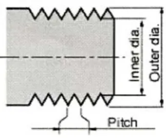
The length of a miniscrew implant is defined as the length of the threaded body and not the length of the
entire screw (Figure 1). MSI lengths range from 5.0 to 12.0 mm.24 The major and minor diameters should always be
Figure 1: MSI Length= Figure 2: Outer & Inner
the Threaded Body Diameters and Pitch
specified when describing MSIs (Figure 2). The major diameter is the maximum diameter determined by the outer diameter of the threads. Major diameters of MSIs range from 1.0 to 2.5 mm.24 The minor diameter refers to the inner (or core) diameter and it ranges from 0.2 to 1.6 mm. The thread depth (Figure 2) is half the difference between the major and minor diameter. The MSI threads form angles with the core. The leading angle is closest to the miniscrew tip and comes into bone contact first upon insertion, while the trailing angle is closest to the MSI head and is the last to contact during placement. Thread design is often defined
11
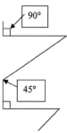
as asymmetric or symmetric. A symmetric thread design is V-shaped, with leading and trailing angles that are congruent (Figure 3). An asymmetric, or buttress, thread is one with a leading angle (towards the tip) that is at 45 degrees to the long axis of the shaft and a trailing angle (towards the head) that is 90 degrees to the long axis of the shaft24 (Figure 4). The pitch is the distance between the threads (Figure 2). When the threads are spaced far apart the miniscrew has a high pitch; conversely, when the threads are close together the miniscrew is low-pitched.
Figure 3: Symmetric Figure 4: Assymmetric Thread Design Thread Design
A miniscrew implant can be drilling,
self-tapping, both, or neither. A self-drilling MSI is one that does not require a pilot hole and has either a sharp,
tapered apex to allow placement,24 or a notch in the tip to drill through the cortex. All MSIs are self-tapping and able to create their own thread as they advance. There are
two different types of self-tapping designs: thread-forming and thread-cutting. The thread-forming design compresses the bone around the thread as the miniscrew advances. The thread-cutting design has either a notch at the tip
parallel to the long axis or a sharpened thread that actually cuts threads into the bone as the miniscrew is inserted.24
Biomechanical terminology used to describe stability testing can be as difficult to understand as design
terminology. The literature is not consistent in the terms used and many terms are synonymous.
BIOMECHANICAL TERMINOLOGY
Engineering divides stresses into two categories; normal and shear. Normal stresses can be either tensile or compressive and are always directed perpendicular to a plane. Tensile stress is generated when a force acts away from the plane and compressive stress involves the
direction of force pushing towards the plane. Shear stress is different because it is directed parallel to the plane of reference.29
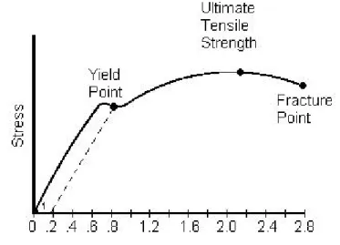
The effect that a stress has on a material is
13
5). The linear portion of the curve can be described as the modulus of elasticity. It measures the strength of the
material, its stiffness, and resistance to load. The
modulus of elasticity of a material represents the amount of stress that can be withstood without permanent
deformation. With increasing stress the yield point of a material is eventually reached. The yield point is the point on the stress-strain curve where strain continues to increase without an increase in the stress indicating
material deformation.29,30
Strain
Figure 5: Stress-Strain Curve
To understand screw mechanics, it is also important to define cutting resistance, stripping torque, and holding strength. Cutting resistance is the resistance of the
density,10,31-33 compression,9 and friction.34 Stripping torque can be described as the point at which the MSI freely
rotates in the bone with no further increase in torque.35 The holding strength of a MSI is its resistance to
displacement (or removal).
DETERMINANTS OF PRIMARY STABILITY
Various techniques have been used to test the primary stability of endosseous implants. In living animals, tests of primary stability must be performed immediately after placement to assure that no healing or bony adaptations have taken place; it can be tested at any time in
non-viable tissue.36 Implant stability depends on the stiffness of the implant, the implant-tissue interface, and the
surrounding tissues.9
Some methods used to test primary stability are more destructive than others. Non-invasive tests include
radiographs, percussion, resonance frequency, placement torque, and reverse removal torque.9 Some of these non-invasive methods can be unreliable due to operator
sensitivity and error.9 Radiographs are problematic because they are a two-dimensional and not easily standardized. Percussion is also not reliable because the test results
15
can differ depending upon the vertical position and angle of the testing instrument as it strikes the implant. In addition, resonance frequency tests are not very accurate because the ear is not sensitive enough to discriminate such frequencies.9 Although reverse torque is typically classified as a non-invasive test, arguments can be made that such a test is in fact quite invasive because damage can occur at the bone-to-implant interface.9 While non-invasive methods for testing can be somewhat unreliable, they are the most ethical and practical in clinical
situations. Of the tests to assess primary stability, placement torque and resonance frequency seem to be the least contraindicated in clinical situations due to their innocuous nature.34
Invasive tests of primary stability are typically used for research purposes. Histologic and histomorphometric techniques are available to assess the implant-tissue interface using light or electron microscopy.9 Histologic techniques evaluate the microscopic nature of the bone surrounding the implant while histomorphometric techniques quantify the percentage of bone-to-implant contact. Both of the aforementioned techniques are problematic with regard to accuracy because of difficulties in specimen preparation due to the marked difference in the physical properties of
the implant and the bone.9 Preparation techniques that allow for the visualization of the metal implant can be
destructive to the surrounding bone. Removal torque is another invasive test which measures the amount of force necessary to remove an implant or disrupt the bone to implant interface. Removal torque is a measurement of interfacial strength in shear and is confounded by the geometry of the implant.9 Pullout testing is an additional invasive test used to measure the pullout resistance of an implant. It involves complete removal of the implant by disrupting the bone to implant interface. It is a common test to measure the influence of implant design on purchase strength in porous materials.36,37
PLACEMENT TORQUE
Torque can be defined as an angular moment of force18 or, for the purpose of this discussion, the rotational force required to insert a screw into bone.14,38 A miniscrew implant is designed to convert torque into compressive
force between it and the object it engages (such as the MSI and the bone). The MSI thread acts like an inclined plane and produces an axial force as it is placed.3 The torque of
17
insertion upon miniscrew implant placement is dependant upon both the design of the MSI and bone properties.
Many studies in various disciplines have found peak insertion torque to be a significant factor in predicting the holding strength of screw-type implants.5,15,39,40
Motoyoshi et al. tested 124 orthodontic miniscrew implants and found the proper miniscrew placement torque to be a matter of balance between force levels that were neither too high nor too low.21 High placement torque has been found to be related to better initial stability;5 however, too high a placement torque can cause osseous damage and MSI loss.41,42 Some have found low placement torque levels to be ideal;19 although, torque levels too low are also
undesirable because a certain level of torsion must be
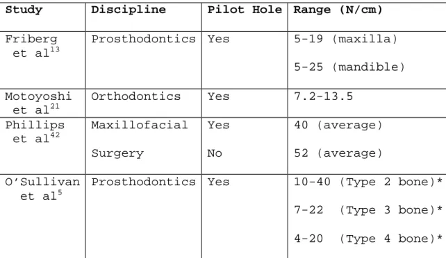
reached to achieve primary stability.9,13 Different ranges of ideal placement torque levels have been reported in the literature, but they vary substantially possibly due to the wide variations in implant design, method of placement, and type of bone in which they were placed. Table 2.2 provides placement torque in N/cm reported in the literature from a variety of disciplines.
Table 2.2: Placement torque values of various screw-type implants
Study Discipline Pilot Hole Range (N/cm)
Friberg et al13
Prosthodontics Yes 5-19 (maxilla) 5-25 (mandible) Motoyoshi et al21 Orthodontics Yes 7.2-13.5 Phillips et al42 Maxillofacial Surgery Yes No 40 (average) 52 (average) O’Sullivan et al5
Prosthodontics Yes 10-40 (Type 2 bone)* 7-22 (Type 3 bone)* 4-20 (Type 4 bone)* *Bone type is based upon bone quality and density.
-Type 1- dense with limited vascularity -Type 2- better vascularity than Type 1
-Types 3 & 4- soft textures with Type 4 being the least successful
PULLOUT STRENGTH
Pullout is a popular test of holding power commonly used in orthopedics, orthodontics, neurosurgery, and
maxillofacial surgery.36 A pullout test directed vertically, with forces parallel to the long-axis of a screw, is one that tests the primary force a screw is designed to resist. Pullout tests are used to evaluate the design of a screw-type implant and the impact it has on the surrounding
19
bone.37 In contrast, shear pullout loads, oriented
directions other than parallel to the long axis of the MSI, test the diameter and material properties of a screw and have very little to do with design.43 When pullout tests are performed either immediately after placement or in
non-viable tissue no adaptive healing responses can occur; so it is a test of primary stability. Pullout tests provide an indication of anchorage values for immediately loaded
miniscrew implants.36
Most information about pullout testing in human bone comes from the orthopedic and neurosurgical literature and involves the vertebrae.15,37,39,44,45 Although there is
information about pullout testing in dog and synthetic bone models, pullout testing of MSIs in a human model has yet to be reported in orthodontics. Although providing useful
clinical information, human models add variation to testing because of the differences in density and cortical
thickness not only among samples, but within the same sample.7,11,46
An argument can be made that pullout testing is more applicable to orthodontics because orthodontic forces are applied directly to the screw head, while in the other disciplines the implants are used to stabilize fractures and are not directly loaded.36 Orthodontic research has
used pullout testing to evaluate the stability of miniscrew implants in dog and synthetic models. Huja et al. performed pullout tests on 56 MSIs placed in dog mandibles and found a positive correlation between cortical bone thickness and resistance to vertical displacement.36 They reported the peak load at failure to be 134.5 N in the anterior and 388.3 N in the posterior regions. In addition, Carano et al. tested three different MSI systems and found a positive correlation between mechanical properties and pullout
resistance. Peak failure loads ranged between 280 N and 370 N, depending upon the design.18
COMBINATION TESTING
At times, invasive and non-invasive methods of primary stability testing are combined to make an overall, two-fold assessment of stability. Combining measures of placement torque and pullout strength would be one such combination. The paring of these tests is important for analyzing the characteristics of the screw thread as a function of its insertion and stablilty.18 Insertion torque has been found to correlate linearly with pull-out strength39,47 and the strength of screw fixation is mainly determined by both of these parameters.44,47 However, some research has
21
hypothesized that osseous damage accumulates around the MSI with high levels of torsion upon insertion, resulting in a decreased pullout strength.45,48 This would suggest a
parabolic effect in which desirable placement torque levels should be neither too low or too high. Low pullout strength has been attributed to placement torque that is above or below a certain range21 and it has been shown that up to 76% of the variability in pullout force can be attributed to placement torque.15 In other words, placement torque and pullout strength go “hand in hand.” The combination of placement torque and pullout strength testing of the same MSI have yet to be performed in orthodontics; however such combination testing is fairly common in other disciplines.
High levels of placement torque do not always result in failure in the bone, but it can also lead to implant bending or fracture.42 This is an increased risk when the insertion is impeded by something such as a tooth root, so care must be taken to assess the integrity of the implant when an object other then the bone is contacted.38 If a root is contacted, one would expect a noticeable rise in
FACTORS AFFECTING PRIMARY STABILITY
Primary stability is affected by the qualities of both the bone and miniscrew implant. The holding power of a
miniscrew implant is not only determined by its design but also by the trauma-induced changes in the bone that result from insertion.17 Failure can occur within the bone, at the bone-MSI interface, or within the MSI itself; it is a
function of the weakest link in the system. The most common mode of failure is shearing within the bone threads that are formed around the screw;17,33,38 this causes the bone to strip and the screw to fail.18
Because the influence of miniscrew implant design on primary stability is often obscured by research about bone quality and placement technique,37 a method of assessing the influence of changes in geometry of the implant system is desirable.34 However, miniscrew implant design and bone quality are not mutually exclusive because MSI design is most critical when bone quality is not optimal.5 The following section examines the influence of bone and MSI design characteristics on primary stability.
23 BONE
Bone plays an important role in miniscrew implant
primary stability. Bone density, cortical thickness, MSI to bone interaction, and bone material properties have all been found to be correlated with placement torque and pullout resistance.
Bone Density
Bone density has been shown to have an influence on primary stability. The present knowledge that relates bone density properties to implant stability comes from the prosthodontic and orthopedic literature. Both disciplines have found bone density to significantly correlate with both torque and pullout strength.15,44,45 The correlation has been found to be reliable enough for equations and
classification systems to be developed based upon the relationship between torque and pullout strength to bone density. For example, Ryken et al.15 developed an equation using bone mineral density and torque to predict pullout strength. In addition, classification systems to grade bone quality49,50 have been based upon the significant correlation between implant placement torque and bone density.10,31-33
Johansson and Strid developed a classification system
widely used in prosthetic dental situations that grades the bone by the resistance of implant placement.50
Dense bone correlates with high placement torque values10,13,31-33,50 and most screw-type implant failures, or loss, have been found to occur when torque values were high in medium to high density bone.13 Bone mineral density also positively relates to pullout strength15,33,44,45 and variation in mean pullout strength has been attributed to anatomical variation in density.44 However, bone density has only been found to account for 28.3% of the variability in pullout force; in contrast, it accounts for 76% of the variablilty in placement torque. The literature is contradictory
because it has been shown that an increase in bone density leads to an increase in both placement torque and pullout strength, while high levels of torsion at placement has been shown to decrease pullout strength. A plethora of variables, including the techniques used, bone and MSI
characteristics, etc., could account for this discrepancy. Understanding bone density variability can be useful in the treatment planning of miniscrew implants.
Differences in bone density have been noted among different orthodontic classifications51 and greater density has been recorded in specimens from older patients.10 Bone density
25
variation has also been noted between the maxilla and mandible13,21 and at different sites within the same
jaw.7,10,13,52,53 However, a difference in density has not been
found when comparing dentate and edentulous mandibles or genders.7 The idea of taking bone density into account when planning for implants is not a new concept because
prosthetic implant selection protocol involves an
assessment of the bone to determine the type of implant and placement technique.10 In bone with low density an implant with a greater surface area is preferred.33 This could be applied to orthodontic situations when considering the proper placement site and corresponding MSI.
Cortical Thickness
The relationship between cortical thickness and placement torque has not been established, but a
significant correlation has been found between cortical thickness and pullout strength.36,48 Cortical bone thickness, like density, varies depending upon location. Values for pullout strength could be influenced, at least partially, by cortical thickness.
Pullout strength has been found to be significantly different between the maxilla and the mandible and even
when comparing anterior and posterior locations within the same jaw.11,36 The bone located in the anterior region of the maxilla and mandible(excluding the mental protuberance) typically has the thinnest cortical bone and the lowest pullout strength; while the bone in the posterior has thicker cortical bone and higher pullout strengths.36
Cortical bone thickness should always be taken into account when analyzing the cause of MSI failure.
MSI to Bone Interaction at Placement
Miniscrew implant primary stability has to do with its interaction with the bone at the time of placement.32 As a miniscrew is inserted and meets resistance, a shear stress is developed along the length of the screw.14 This shear force can cause microfractures within the bone which can effect the healing process42,48,54 and lead to degeneration and necrosis at the interface.9,17,54 The bone damaged during insertion will be targeted for repair and could result in screw loosening.55
Cutting resistance of the bone is a function of the friction at the bone to screw interface34 and is increased as bone material packs around the miniscrew implant.13 This, in combination with the increased screw surface area
27
interacting with the bone, explains why placement torque increases as the MSI is inserted. Friction increases the torque required to place a MSI. During placement, applied torque is used to cut threads and to overcome friction between screw threads and the bone.3 Tension can only be induced into the system when the torque needed to overcome friction is exceeded.14 Only about 15% of the torque applied to a MSI is converted into axial force; the rest is lost due to factors such as friction between the bone and the MSI.3
A reduction in friction could help reduce the torque at placement and thus limit osseous damage. To reduce
friction, it has been recommended to wet the MSI and insert it with continuous rotation. Wetting with blood or saline prior to insertion produces an effect similar to oil in a crankshift.35,56 In addition, a screw-type implant that is inserted with continuous rotation generates less torque than one that is inserted intermittently. A pause in rotation allows the bone to relax around the implant, resulting in more friction to be overcome as rotation resumes and the generation of more torque.35,56
Bone Material Properties and Response
Bone material properties play an important role in the primary stability of miniscrew implants. The holding power of a screw-type implant is related to the shearing strength of the material into which it is inserted.14 Pullout is a test of shear strength.43 The MSI’s interaction with the bone upon insertion can also compromise its holding
potential because the strength and integrity of the bone surrounding the screw are partially a function of the trauma caused during insertion.17
As mentioned earlier, the interdigitation of miniscrew implants and bone offer two potential sources for failure: either in the threads of the bone or the MSI threads.38
Failures tend to occur due to the bending of bone threads interdigitated between the MSI threads. Osseous failure occurs parallel to the long axis of the MSI core in a plane of natural cleavage(i.e., the plane that is parallel to the long axis at the extent of the major diameter).17 This
failure is related to the strength of the bone for a distance of about two millimeters around the screw.17
The reasons for failure of miniscrew implants can be identified by examining the bone following pullout testing. Bone damage during placement will theoretically shear in a
29
line parallel to the outer edge of the MSI threads, causing a cylindrical defect upon pullout.12 When the MSI failure actually happens at the time of pull-out testing, a conical piece of bone strips.3 Examination of the defect after
testing provides valuable information about the cause of failure and can aid in the determination of further
research projects.
SCREW-TYPE IMPLANT DESIGN CHARACTERISTICS
There are a variety of screw-type implants available for medical use, but their designs have not been fully studied.56 The limited amount of literature available on design mostly comes from disciplines other than
orthodontics. Implant design has been shown to influence primary stability; different designs have produced
different results.34 Geometry and material are significant factors in miniscrew implant biomechanics and their
alteration could change the MSI’s mechanical strength.18 Various studies have found that characteristics such as length, diameter, thread depth, thread design, and pitch to be important in determining holding power.11,43,45,56 However, available MSIs differ in many ways, including geometry,
material, dimension, and insertion technique (such as the presence or absence of a pilot hole).17
In the next sections, characteristics of miniscrew implants will be examined individually. Some of these characteristics have been more fully investigated than others. Determining the effects of each characteristic and its role in the overall design will aid in the planning of new designs. New designs could result in a decrease of trauma and an increase in treatment planning options.
Length
The orthodontic literature does not contain
information on the effect of miniscrew implant length on primary stability. However, the orthopedic literature shows that implant length is one of the most important variables in mechanical strength.18 The relationship between length and placement torque has not been investigated, but a correlation with pullout strength has been shown. Hitchon et al. tested 201 screw-type implants in frozen human cadaver specimens and found length to have a significant effect on pullout strength, with longer screws having a higher resistance to displacement.45 This might be expected
31
because holding power is directly proportional to the amount of thread engagement.54
Diameter
As with length, the relationship between miniscrew implant diameter and primary stability has yet to be examined in orthodontics. Other disciplines have found diameter to be the one of the most important variables for mechanical strength.18 It has influence on both the torque and pullout strength.
Using fresh bovine bone, Nunamaker and Perren tested placement torque of screw-type implants of various
diameters and found insertion torque to increase with an increase in minor diameter.57 The increase in surface area that results from increasing the screw minor diameter creates more friction and increases torque.3 The minor diameter of a screw-type implant can become too small and higher torque levels can cause breakage; this is referred to as breaking torque. The breaking torque of a screw is equal to the ratio of the cube of its respective minor diameter.57 Carano et al. suggested that a minor diameter reduction of as little as 0.2 mm may reduce the resistance to breakage of the miniscrew implants by 50%. An overall
minor diameter of less than 1.5 mm is not recommended for orthodontic purposes because humans can apply enough
torsional force to break smaller screws.18 However, if placement torque could be reduced through the addition of other design features, it is theoretically possible to further reduce screw size.
While placement torque is correlated with minor
diameter, resistance to pullout correlates with the major diameter. Major diameter has been found to be one of the main factors in primary stability.17,58 DeCoster et al.
isolated screw-type implant characteristics and found major diameter to increase linearly with resistance to pullout in a synthetic bone model.11 It is one of the most important dimensions for pullout strength because the tensile
resistance of the screw-type implant corresponds to the cube of its major diameter.58
Thread Depth
While thread depth has yet to be considered in the orthodontic literature, it is fairly commonplace in orthopedics. It can be described as half the difference between the major and minor diameters. Shallow threads are typically used for cortical bone and deep threads are used
33
for cancellous bone.3 Greater depth is thought to provide more holding power because of an increased bone volume between the threads and increased bone to screw contact.12 The relationship between thread depth and placement torque is unknown, but information about the effect of thread depth on pullout is available. Chapman et al. tested the pullout strength of 12 different screw-type implant designs and found that an increased thread depth allows for greater purchase strength and pullout resistance in porous
materials.11,43 DeCoster et al. performed pullout on six different screw-type implants and came to the same
conclusion.11 Based upon these findings, a greater thread depth would be recommended for orthodontic applications to maximize resistance to displacement under force loads.
Thread Design
The thread is designed to facilitate placement, prevent loosening, offer strength, and withstand axial loads.3 Threads are most commonly designed in two ways: symmetric or asymmetric. The literature provides different hypotheses as to why one design should be used over
another. Perren et al. postulated that symmetric threads produce increased friction at placement, but greater
pullout strength. The increase in pullout strength is due to an increase in the amount of bone at the outer edge of the thread in a symmetric design since the height of the screw threads reaches zero at the outer edge.3 They also stated that the symmetric thread offers mechanical
advantages by contributing to the stiffness of the screw.3 With regard to the asymmetric thread design, Perren et al. hypothesized that the asymmetric design offers the
advantages of the symmetrical design without the disadvantages by having a contacting flank that is perpendicular to the long axis to resist the force of displacement.3 In addition, Carano et al. found that the asymmetric threads have a geometry that facilitates
insertion while obstructing removal.18
Orthodontic miniscrew implants use both designs, but the literature supporting one design over another is
lacking. However, it was hypothesized by Carano et al. that a combination of insertion and pullout tests are important for the analysis of thread design as a function of screw stability.18 They also found that MSI resistance to
torsional stress during placement is related to the design of the screw thread.18 More testing is needed to determine which design is best for orthodontic purposes.
35
Self-Drilling/Self-Tapping
Research pertaining to the effects of self-drilling and self-tapping characteristics on primary stability of screw-type implants comes largely from the orthopedic literature. Although self-drilling and self-tapping miniscrew implants are commonly used, research in
orthodontics has yet to compare the differences between MSIs requiring a pilot hole and those that are self-tapping. The relatively small size of orthodontic MSIs gives them the advantage of more than one option in tip design. In orthodontics there is confusion concerning the definitions of self-drilling or self-tapping designs, possibly due to the variety of designs available.
Little has been scientifically proven regarding the effects that self-drilling characteristics have on primary stability, but educated hypotheses have been offered. Self-drilling screw-type implants are thought to have greater bone contact than those requiring a pilot hole36 Greater bone contact should positively effect stability.
Self-drilling screws are also thought to have a higher placement torque due to friction which could prove detrimental. In addition, Perren et al. found that a self-drilling tip must be able to cut a pilot hole at the same rate at which the
thread advances the screw into the bone. For example, an orthopedic screw with a pitch of 1.75 mm and a 4.5 mm diameter cannot be matched by the drilling effect of any type of tip because the pitch will not allow for efficient cutting and advancement with the given diameter.3 A balance in design is required to prevent the development of undue stress in the bone during insertion.
Self-tapping is the ability of a miniscrew to create its own thread as it advances. The literature pertaining to the effects of self-tapping screws on placement torque and initial stability is controversial. Phillips et al. and Al-Nawas et al. have shown that self-tapping implants have a higher placement torque and greater initial stability when compared with non-self-tapping.8,42 The higher value of
placement torque with the self-tapping screw was thought to be due to the excess torque needed to overcome the friction of cutting threads.42 In contrast, Ansell and Scales have shown less torque during the insertion of self-tapping screws; this could be a result of the screw-type implants being inserted with intermittent rotation.56
The method of placement (i.e. continuous versus
intermittent rotation) should be considered when deciding whether or not to use a self-tapping design. Ansell et al. found high placement torque levels while placing
non-self-37
tapping screws with intermittent rotation.56 Non-self-tapping screws have to overcome more friction than screws which are self-tapping because the threads are not cutting. A pause in movement allows the bone to relax around the non-self-tapping thread, which increases friction and placement torque.42
Some of the discrepancy in the literature with regard to the effects of self-tapping characteristics on primary stability could be as a result of inconsistent or flawed designs. Self-tapping screw-type implants can be either thread forming or thread cutting. The typical thread-cutting design available in orthodontics has a thread-cutting flute which extends only partially along the length of the tapered portion of the miniscrew implant. This does not allow for the cutting of threads beyond the point of flute extension and, as the major diameter continues to increase, sufficient space has not been tapped to allow for the
insertion of the remaining threaded portion. Perren et al. demonstrated that thread cutting self-tapping implants should have flutes that continue until the cylindrical
portion of the implant is reached.3 They also suggested that high torque at insertion, reduced holding strength, and a rise in temperature at insertion can be fairly well
There are many conflicting reports regarding the placement torque and pullout strength of self-tapping and non-self-tapping screw implants. Some of the disparity may be due to the failure to compare the differences between thread-forming and thread-cutting self-tapping screws. More research should be done to better understand these
characteristics of screw design.
Taper
The taper of screw-type implants ranges from completely cylindrical to entirely tapered. Most
orthodontic miniscrew implants are at least partially tapered, with many having a combined design that starts tapered until the full diameter is reached and then
progresses on cylindrically. Although Carano et al. were not specifically studying taper during testing, they noted that cylindrical screws have a constant insertion torque in any given material as long as the pitch is held constant.18 This also holds true for the cylindrical portion of a combined design. In comparison, they also found that the placement torque of tapered screws increase throughout placement.18 The effects of MSI taper have yet to be fully studied.
39
Multiple Threads
A screw-type implant with a multiple thread design is one which has a series of threads wrapped around the core. A common example of such a design is a water bottle or plastic milk container. It was first described by Bechtol et al.59 in 1959 and then later introduced into dentistry by Nobel Biocare as the Mark IV prosthetic implant.5
Multiple-threaded designs are not common in either medicine or dentistry. In addition, there is no mention of this design characteristic in the orthodontic literature. The existing knowledge of the effects of a
multiple-threaded design is limited, but there has been mention of its influence on both placement torque and pullout
strength. O’Sullivan et al. found the double-threaded Mark IV system to have a higher insertion torque than those with a single thread, but greater stability. They hypothesized that the double thread allowed faster placement without increasing the energy at the bone-to-implant interface.5 In support, da Cunha et al. found a double-threaded design to reduce placement time by 50% without an increase in heat production.34 Boyle et al., who included a multiple-threaded design in a study of surgical emergency screws, found those
with at least three threads have the largest pullout resistance, and thus greatest stability.35
It has been suggested that the stability of the
multiple-threaded design is less affected by the quality of the bone.5 This is important because many studies have
reported bone quality is correlated with placement torque and pullout strength.10,14,15 A design that is less affected by parameters outside the control of the clinician, such as bone quality, is preferable.
Pitch
Pitch is another characteristic of miniscrew implant design that has yet to be studied in orthodontics. Like many of the characteristics previously mentioned, most of the information available comes from the orthopedic
literature. The important role of thread pitch has been established. It has been suggested that pitch is clinically more important than major diameter because the major
diameter is limited by the bone site and space available.11 Pitch is not limited by available space and its effect on primary stability has been noted.
The effect of pitch on placement torque has not yet been studied. The pitch of a screw-type implant determines
41
the amount a screw advances with each turn,3 which should, in theory, have an effect on placement torque. A greater amount of advancement per turn creates higher axial force which may well increase torsion at placement.
However, available studies indicate that pitch is negatively related to pullout strength. Chapman et al. tested the pullout strength of 12 different screw designs and found that decreases in pitch increase the resistance to pullout.43 DeCoster et al., who performed pullout testing on three different designs, also found that a decrease in pitch significantly increases the pullout resistance.11 A decrease in pitch is thought to increase the screw purchase strength in porous materials.43
Since the significance of the bone-to-miniscrew
implant contact has been established; the thickness of the bone in which a screw is to be inserted must be taken into consideration when choosing a pitch. In bone that is only 1-2 mm thick, a screw with a pitch angle of 0.6-1.0 mm will only have 2-4 threads in contact with cortical bone. This limited area of contact may produce micromovements leading to bone resorption and loss of the implant.42
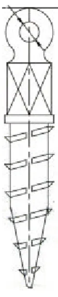
Flutes
A flute is a longitudinal groove in the threaded portion of a screw used for cutting and clearing bone chips. Flutes vary in length and number and are a common feature in self-tapping screw-type implants. The variation in the length and number of flutes has a significant effect on the insertion torque and pullout strength. The effect of flutes has yet to be studied by orthodontics, but
literature is available in the disciplines of surgery and biomechanics.
Cutting flutes have a significant influence on the placement torque of screw-type implants. Yerby et al. found that as the number and length of cutting flutes increases, there is a decrease in placement torque and cortical
damage.47 Higher torque levels have been found for screw-type implants with fewer or shorter cutting flutes because the design allows for less clearance of bone chips which tend to accumulate around the screw threads and provide resistance to insertion.12,47,60 This would also explain why fluted designs have been found to be easier to insert in comparison to non-fluted designs.47,59,61,62 The study by Yerby et al. recommends a minimum of three, full-length flutes to avoid stripping threads and facilitate advancement.47
43
The effect flutes have on pullout strength is not clear. It has been reported that the presence of flutes both decreases47,59,61 and increases35,62 pullout strength. Arguments can be made to support both notions depending upon the timing of pullout testing. A decreased resistance to pullout should be seen in primary stability testing
because the fluted region of a screw does not have as great a holding power as the fully threaded region.33,59 An
increased resistance might be expected with secondary
stability because of the possibility of bone forming in the fluted region.
The temporary nature of orthodontic miniscrew implants could be problematic for the fluted design. This is because bone may grow into the flutes and cause problems with
removal.3,56 Problems may also arise as the bone chips fill the flutes during placement, which could increase the chances of splitting the bone.35 This can be alleviated by placing grooves in the shank, or core, of the screw implant thereby creating a space for the bone chips to collect.35 The aforementioned is not problematic for larger screw-type implants which are used in other disciplines, but grooves may compromise the strength of miniscrew implants because of their small dimensions.
PURPOSE
The purpose of the present study is to isolate several characteristics of miniscrew implant design in order to determine their effect on primary stability. One design characteristic will be altered at a time and placement
torque and pullout tests will be performed in comparison to a control to assess the characteristic’s influence on MSI stability. Such an experiment has never been performed and could lead to better MSI designs. Orthodontic miniscrews are often loaded immediately23 making this experiment clinically applicable. Even though pullout tests do not have direct clinical involvement because orthodontic forces are not sufficient to strip miniscrew implants from their sites,18 they are useful in analyzing MSI geometry as a function of stability.18
45
REFERENCES CITED
1. Cheng S, Tseng I, Lee J, Kok S. A prospective study of the risk factors associated with failure of mini-implants used for orthodontic anchorage. Int J Oral Maxillofac Implants 2004;19:100-106.
2. Kakria HL. Evolution in fracture management. MJAFI 2005;61:311-312.
3. Perren SM, Cordey J, Baumgart F, Rahn BA, Schatzer J. Technical and biomechanical aspects of screws used for bone surgery. Int J Orthoped Trauma 1992;2:31-48.
4. Gainsforth BL, Higley LB. A study of orthodontic anchorage possibilities in basal bone. Am J Orthod Oral Surg 1945;31:406-416.
5. O'Sullivan D, Sennerby L, Meredith N. Measurements comparing the initial stability of five designs of dental implants: a human cadaver study. Clin Implant Dent Relat Res 2000;2:85-92.
6. Fanuscu MI, Chang TL. Three-dimensional morphometric analysis of human cadaver bone: microstructural data from maxilla and mandible. Clin Oral Impl Res 2004;15:213-218. 7. Schwartz-Dabney CL, Dechow PC. Edentulation alters
material properties of cortical bone in the human mandible. J Dent Res 2002;81:613-617.
8. Al-Nawas B, Wagner W, Grotz KA. Insertion torque and resonance frequency analysis of dental implant systems in an animal model with loaded implants. Int J Oral Maxillofac Implants 2006;21:726-732.
9. Meredith N. Assesment of implant stability as a prognastic determinant. Int J Prost 1998;II:491-501.
10. Turkyilmaz I, Tozum TF, Tumer C, Ozbek EN. Assessment of correlation between computerized tomography values of the bone, and maximum torque and resonance frequency values at dental implant placement. J Oral Rehab 2006;33:881-888.
11. DeCoster TA, Heetderks DB, Downey DJ, Ferries JS, Jones W. Optimizing bone screw pullout force. J Orthoped Trauma 1990;4:169-174.
12. Johnson NL, Galuppo LD, Stover SM, Taylor KT. An in vitro biomechanical comparison of the insertion variables and pullout mechanical properties of AO 6.5-mm standard cancellous and 7.3-mm self-tapping, cannulated bone screws in foal femoral bone. Vet Surg 2004;33:681-690.
13. Friberg B, Sennerby L, Grondahl K, Bergstrom C, Back T, Lekholm U. On cutting torque measurements during implant placement: a three-year clinical prospective study Clin Implant Dent Rel Res 1999;I:75-83.
14. Hughes AN, Jordan BA. The mechanical properties of surgical bone screws and some aspects of insertion practice. Injury 1972;4:25-38.
15. Ryken TC, Clausen JD, Traynelis VC, Goel VK.
Biomechanical analysis of bone mineral density, insertion technique, screw torque, and holding strength of anterior cervical plate screws. J Neurosurg 1995;83:324-329.
16. Pitzen TF, Barbier F, Steudel WI. Insertion torque and pullout force of rescue screws for anterior cervical plate fixation in a fatigued initial pilot hole. J Neurosurg: Spine 2004;1:198-201.
17. Schatkzer J, Sanderson R, Murnaghan JP. The holding power of orthopedic screws in vivo. Clin Orthoped Rel Res 1975:115-126.
18. Carano A, Lonardo P, Velo S, Incorvati C. Mechanical properties of three different commercially available miniscrews for skeletal anchorage. Prog Orthod 2005;6:82-97.
19. Kim J, Ahn S, Chang Y. Histomorphometric and mechanical analysis of the drill-free screw as orthodontic anchorage. Am J Orthod Dentofacial Orthop 2005;128:190-194.
20. Kravitz ND, Kusnoto B. Risks and complications of orthodontic miniscrews. Am J Orthod Dentofacial Orthop 2007;131:S43-S51.
47
21. Motoyoshi M, Hirabayashi M, Uemura M, Shimizu N.
Recommended placement torque when tightening an orthodontic mini-implant. Clin Oral Impl Res 2006;17:109-114.
22. Brunski JB. Biomechanical factors affecting the bone-dental implant interface. Clin Mater 1992;10:153-201. 23. Chen YJ, Chen YH, Lin LD, Yao CC. Removal torque of miniscrews used for orthodontic anchorage- a preliminary report. Int J Oral & Maxillofac Implants 2006;21:283-289. 24. Cope JB. OrthoTADs: The Clinical Guide and Atlas. Dallas: Under Dog Media; 2007.
25. Heller JG, Bradley T, Estes MS, Diop A. Biomechanical study of screws in the lateral masses: Variables affecting pull-out resistance J Bone Joint Surg [Am] 1996;78:1315-1321.
26. Carter DR, Giori NJ. Effect of mechanical stress on tissue differentiation in the bony implant bed. In: Davies JE, editor. The bone-biomaterial interface. Toronto:
University of Toronto Press; 1991: p. 367-379.
27. Goodman S, Wang JS, Aspenberg P. Difference in bone ingrowth after one versus two daily episodes of
micromotion: experiments with titianium chambers in rabbits J Biomed Mater Res 1993;27:1419-1424.
28. Roberts WE, Smith RK, Zilberman Y, Mozsary PG, Smith RS. Osseous adaptation to continuous loading of rigid endosseous implants. Am J Orthod Dentofacial Orthop 1984;86:95-111.
29. Byars EF, Snyder RD. Engineering Mechanics of
Deformable Bodies. Scranton: International Text Co.; 1969. 30. Morrow HW. Statistics and Strength of Materials.
Columbus: Prentice Hall; 1998.
31. Akca K, Chang TL, Tekdemir I, Fanuscu MI. Biomechanical aspects of initial intraosseous stability and implant
design: a quantitative micro-morphometric analysis. Clin Oral Implants Res 2006;17:465-472.
32. Friberg B, Sennerby L, Roos J, Lekholm U.
Identification of bone quality in conjunction with insertion of titianium implants. A pilot study in jaw autopsy specimens. Clin Oral Implants Res 1995;6:213-219. 33. Ikumi N, Tsutsumi S. Assessment of correlation between computerized tomography values of the bone and cutting torque values at implant placement. Int J Oral Maxillofac Implants 2005;20:253-260.
34. da Cunha HA, Francischone CE, Filho HN, de Oliveira RC. A comparison between cutting torque and resonance frequency in the assessment of primary stability and final torque capacity of standard and TiUnite single-tooth implants under immediate loading. Int J Oral Maxillofac Implants 2004;19:578-585.
35. Boyle III JM, Frost DE, Foley WL, Grady JJ. Torque and pullout analysis of six currently available self-tapping and "emergency" screws. J Oral Maxillofac Surg 1993;51:45-50.
36. Huja SS, Litsky AS, Beck FM, Johnson KA, Larsen PE. Pull-out strength of monocortical screws placed in the maxillae and mandibles of dogs. Am J Orthod Dentofacial Orthop 2005;127:307-313.
37. Pfeiffer M, Gilbertson LG, Goel VK, Griss P, Keller JC, Ryken TC, Hoffman HE. Effect of Specimen Fixation Method on Pullout Tests of Pedical Screws. Spine 1996;21:1037-1044. 38. Collinge CA, Stern S, Cordes S, Lautenschlager EP. Mechanical properties of small fragment screws. Clin Orthoped Rel Res 2000:277-284.
39. Zdeblick TA, Kunz MS, Cooke ME, McCabe R. Pedicle Screw Pullout Strength: Correlation with Insertional Torque.
Spine 1993;18:1673-1676.
40. Ottoni JM, Oliveira ZF, Mansini R, Cabral AM. Correlation between placement torque and survival of single-tooth implants. Int J Oral & Maxillofac Implants 2005;20:769-776.
41. Niimi A, Ozeki K, Ueda M, Nakayama B. A comparative study of removal torque of endosseous implants in the fibula, iliac crest, and scapula of cadavers: preliminary report Clin Oral Impl Res 1997;8:286-289.
49
42. Phillips JH, Rahn BA. Comparison of compression and torque measurements of self-tapping and pretapped screws. Plast Reconstr Surg 1989;83:447-456.
43. Chapman JR, Harrington RM, Lee KM, Anderson PA, Tencer AF, Kowalski D. Factors affecting the pullout strength of cancellous bone screws. J Biomech Eng 1996;118:391-398. 44. Pitzen T, Barbier D, Tintinger F, Steudel WI,
Strowitzki M. Screw fixation to the posterior cortical shell does not influence peak torque and pullout in anterior cervical plating. Eur Spine J 2002;11:494-499. 45. Hitchon PW, Brenton MD, Coppes JK, From AM, Torner JC. Factors affecting the pullout strength of self-drilling and self-tapping anterior cervical screws. Spine 2003;28:9-13. 46. Wagenknecht M, Andrianne Y, Burny F, Donkerwolcke M. Study of the mechanical characteristics of external
fixation pin anchorage. Preliminary results. Orthoped 1984;7:629-632.
47. Yerby S, Scott CC, Evans NJ, Messing KL, Carter DR. Effect of cutting flute design on cortical bone screw insertion torque and pullout strength. J Orthoped Trauma 2001;15:216-221.
48. Cleek TM, Reynolds KJ, Hearn TC. Effect of screw torque level on cortical bone pullout strength. J Orthop Trauma 2007;21:117-123.
49. Lekholm U, Zarb GA. Tissue-Integrated Prostheses: Osseointegration in Clinical Dentistry. In: Zarb GA,
Albrektsson T. editor. Patient selection and preparation. Chicago: Quintessence; 1985: p. 199-209.
50. Johansson P, Strid KG. Assessment of bone quality from placement resistance during implant surgery. Int J Oral Maxillofac Implants 1994;9:279-288.
51. Jensen O. Site classification for the osseointegrated implant. J Prost Dent 1989;1:228-234.
52. Klinge B, Johansson CB, Albrektsson T, Hallstrom H, Engdahl T. A new method to obtain bone biopsys at implant sites peri-operatively: technique and bone structure. Clin Oral Impl Res 1995;6:91-95.
53. Ulm CW, Kneissel M, Hahn M, Solar P, Matejka M, Donath K. Characteristics of the cancellous bone of edentulous mandibles. Clin Oral Impl Res 1997;8:125-130.
54. Lyon WF, Cochran JR, Smith L. Actual holding power of various screws in bone. Annals of Surgery 1941;114:376-384. 55. Seebeck J, Goldhahn J, Morlock MM, et al. Mechanical behavior of screws in normal and osteoporotic bone.
Osteoporos Int 2005;16:S107-111.
56. Ansell RM, Scales JT. A study of some factors which effect the strength of screws and their insertion and holding power in bone. J Biomech 1968;1:279-285.
57. Nunamaker DM, Perren SM. Force measurements in screw fixation. J Biomech 1976;9:669-675.
58. Heam TC, Schatzker J, Wolfson N. Extraction strength of cannuated cancellous bone screws. J Orthop Trauma
1993;7:138-141.
59. Bechtol CO, Ferguson AB, Lang PG. Metals and
Engineering in Bone and Joint Surgery. In: Bechtol CO, editor. Internal fixation with plates and screws.
Baltimore: Williams and Wilkins; 1959.
60. Uhl RL. The biomechanics of screws. Orthoped Review 1989;18:1302-1307.
61. Koranyi E, Bowman CE, Knecht CD, et al. Holding power of orthopedic screws in bone. Clin Orthop 1970;72:283-286. 62. Evans M, Spencer M, Wang Q, et al. Design and testing of external fixator bone screws. J Biomed Eng 1990;12:457-462.
51
CHAPTER 3: JOURNAL ARTICLE
ABSTRACT
Purpose: This study was designed to isolate two design characteristics of miniscrew implants (MSIs), pitch and fluting, and to determine their effects on primary
stability. Methods: Maximum placement torque and pullout strength of MSIs specifically fabricated for this
experiment were compared to a control MSI using synt