Tag-In-Tag: Efficient Flow Table Management in
SDN Switches
Subhasis Banerjee
Siemens Corporate Technology Research and Technology Center, India Email:[email protected]Kalapriya Kannan
IBM Research LabBangalore, INDIA
Email:[email protected]
Abstract—Ternary Content Addressable Memory (TCAM) with O(1) look up performance has become the obvious and irreplaceable choice of high performance switching hardware. However, emerging network paradigm, especially Software De-fined Networking (SDN), has changed the nature of operations and the rate of access in this memory subsystem. These conditions are expected to adversely impact TCAM power consumption, increase the silicon area and hence are likely to bring down the expected performance. In this paper we propose Tag-In-Tagan approach that exploits SDN features and replaces the flow entries with two layers of simpler and shorter tags. One level of tagging exploits the availability of unique path for individual flows from the ingress switch to egress switch that can be computeda-priori. Second level of tagging allows finer identification of the flows to enable flow specific actions. Double tagging helps in preserving the finer benefits of the SDNs while providing highest level of compaction to the flow entries in the flow tables. Through various experiments using real world and synthetic data we show that our approach can accommodate 15 times more flow entries in a fixed size TCAM whereas power consumption per-flow is reduced by 80% compared to an unoptimized SDN enabled switch.
I. INTRODUCTION
Flow tables are accessed for every single packet that arrives in the switching device and therefore lie in the critical path of the packet processing operation. In a high performance, high throughput network environment, e.g., data center network, the demand on the low latency, line rate packet processing has made TCAM the default choice of memory subsystem for storing flow tables [1]. While TCAMs are superbly fast (𝑂(1) lookup, typically 1 cycle lookup operation), the usable size is limited due to their notoriously high power consumption. Smaller sized TCAM, that can only accommodate smaller flow table, reduces the goodness gains (amount of bandwidth obtained for transfers of data) due to frequent broadcasts on the non-available entries in the flow table [2]. This gap between the usable size and the required size limits the packet pro-cessing speed and is likely to increase with emerging network paradigms such as SDN. This is due to two fundamental changes adopted in the SDN, viz. (a) SDN redefines a flow with 15 tuple (356 bits being used for flow definition) and hence requires more memory footprint to fit a flow entry, (b) SDN enables finer control over the flow and that may lead to increase in number of flow entries. Therefore to maintain the same hit rate to high speed TCAM one would require larger size memory to accommodate more flow entries.
Conventional layer 2 (L2) and layer 3 (L3) switches assign 2-5 field tuples depending on the layer where these switches are deployed. However, OpenFlow, a widely adopted standard for SDN, uses 15 field tuple with a total number of 356 bits to define a flow [3]. This is approximately 7 times more than that of an L2 switching device which uses 60 bits (MAC+VLAN tag). This can impact an SDN switch in several ways: Firstly, it requires higher sized TCAM for storing the same number of flows that an L2 switch can hold. Secondly, this can quickly fill up the flow tables (with micro-flows being identified as flows) and lead to flow table explosion. Recent studies have established that the flow arrival to the SDN switches can be of the order of 72,000 flows/sec [4]. Thirdly, the number of operations which have been mostly the lookup operations, will now be converted into the insert operations. It has been established in [5] that there is 1 insert operation for every 3 lookup operations in SDN networks. The combined effect of all these results in higher power dissipation in TCAM with more demands on the silicon space on switch. Thus an efficient management of flow table is an important problem in the SDN network to reduce the power and increase the number of manageable entries in the flow table.
In an attempt to optimize flow table space, we focus on reducing the size of the flow table entries. We introduce two layers of tagging in a flow to reduce the number of bits de-scribing a flow within the switch. OurTag-In-Tagmechanism associates a tag for a given path, referred to as ‘PATH TAG’ (PT), and uses it for routing the packets. Another tag, referred to as ‘FLOW TAG’ (FT), is used to associate packets to a flow. A ‘PATH TAG’ encapsulates the ‘FLOW TAG’. PT exploits path similarity by different packets and is used as routable tag to identify the actions associated for routing the packets belonging the path. FT is used for identifying the flow by the switches for providing fine grained resource management. It should be noted that by using the PT or the FT neither the routes are compromised nor the information regarding the flows is lost. Thus, all existing mechanisms for routing the packets, discovering the routes would work as-is, except that the flow entries are no longer the tuple but PT and FT that uniquely identifies these flows. Reduction of the flow entry size will provide triple benefits: (a) It helps preserve the purpose of SDN’s to identify micro-flows uniquely compared to options of combining multiple flows into single flows (as
used by wildcarded options of L2/L3 switches), (b) reduce the total dynamic power dissipation as power is function of the circuit complexity and is proportional to the number of bits used, (c) provisions to store more flow entries in the same TCAM size compared to 356-bit entries.
The flexibility in programming the network provided by the SDN can be exploited to realize such a framework. The switches store only the PT/FT in the table. Our approach requires no modification to the network framework and all our steps are within the framework of the SDN. We show that by using our approach about 80% gain on power can be achieved and larger number of flows can be accommodated with the the same sized flow table. Unless otherwise stated, we consider Data Center (DC) Networks (by referring them as networks) in our explanation and experiments.
Our contribution can be summarized as follows: (i) We investigate the impact of SDN implementation on TCAM based high performance network switches. (ii) We propose an approach to reduce the size of flow entries in OpenFlow (SDN).
The rest of the paper is organized as follows: we set the motivation of our work in section II. Our approach of
Tag-In-Tag based flow entry condensation is presented in section
III. We present assessment and evaluation of our approach in section IV. We describe the prior work in section V. Finally we conclude in section VI.
II. MOTIVATION: SDN OVERHEAD ONSWITCHES
A. Design with TCAM: Impact on Flow Lookup
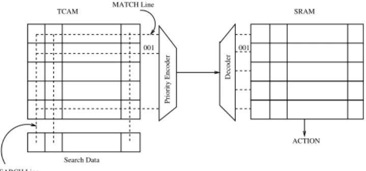
Fig. 1 shows a conceptual model of TCAM in a switch. Usually a combination of TCAM and SRAM (Static Random Access Memory) is used to forward a packet based on appro-priate actions. The TCAM is a fully associative array of bits which are used for storing flow entries. Any packet arriving to the switch will undergo lookup operation to find a match in TCAM. The incoming packet may contain wildcard entries in the address field which may lead to multiple matches in TCAM. In such cases, the entry that matches with longest prefix is selected. This logic is in-built along with the TCAM cells by incorporating a priority encoder. Adjacent to TCAM, there is an array of SRAM that contains the action part to guide the packet through appropriate port in the switch.
TCAM SRAM Search Data MATCH Line SEARCH Line Priority Encoder Decoder ACTION 001 001
Fig. 1: TCAM/SRAM operation in a switch
An alternative to TCAM/SRAM lookup is to use dedi-cated processing of packet through ASIP (Application Specific Instruction-set Processor) with local caching of data in SRAM. This requires an efficient algorithm to find longest prefix match. There are few attempts to organize data cache for such implementation to improve lookup time [6]. However, this cannot match the line rate as there are multiple access to fetch the entire data element from the cache and therefore we focus on TCAM/SRAM.
Current day switches have TCAM of size ranging from 1Mbit - 2Mbit. This indicates that current sizes of TCAM is insufficient to hold the number of active entries required for an OpenFlow enabled switch. In general commercial switching devices employ two kinds of memory cells, one a SRAM only chip for storing full entries (also referred to as ’Exact Match Entries’) which can be looked up using a direct hashing algorithm and another a TCAM/SRAM combination which exploits don’t care state to store the wild card entries. The SRAM consumes about 50 times less power with 20 times more access latency compared to the TCAM. Since in SDN environment (e.g., DCs) low latency lookup is preferred due to the nature and criticality of the applications, TCAM wins over SRAM even for exact match entries.
TCAM operations are primarily categorized into read and write operations and each of these operations are associated with different power consumption. Basic Flow entry operations are insert, delete, modify and search. Using the TCAM power simulator [7], average power dissipation for 100 k entry TCAM in a L2 switch consumes195,167𝑛𝐽 and447,065𝑛𝐽 respectively for write/insert and search/lookup operation. The estimated power number for an OpenFlow switch having same TCAM size is792,677𝑛𝐽 and1,807,142𝑛𝐽.
B. Impact on OpenFlow Enabled Switches
We use OpenFlow as implementation standard of SDN and use OpenFlow and SDN interchangeably. As mentioned before, OpenFlow characterizes a flow using 15 field tuple. The design philosophy behind choosing the large size tuple is to attain fine grained traffic classification. Traffic classification in existing switching devices has been coarse grained. For instance, majority of the switches employ per destination based traffic classification and therefore the flow/lookup table consists of entries equivalent to the number of the destination ports. In this case one can conclude that only few flow entries (as many as number of destination ports) can classify all the incoming traffic. Clearly, per destination based approaches
cannotachieve efficient resource utilization. In an attempt to
achieve fine grained resource utilization, OpenFlow defines larger sized tuples.
There are two primary design challenges for an OpenFlow switch. First, the volume of flows recognizable by the switch explodes. Theoretically, 2356 flow entries are possible at any point in time (356 bits to define a flow). The actual number of flow entries are dependent on network parameters such as number of actions, hosts, flows etc. The practical number is something around 1 Million, although it is quite high
compared to the conventional switch. Second, the nature of operations in the OpenFlow switches are quite different. In conventional switches, the number of flows being small major-ity of operations are just lookup operations. With OpenFlow, the number of flows being higher, the number of possible entries to be stored is large. Therefore, operations such as writes, invalidations, update of flow table entries will now become prominent apart from just lookup.
To understand the stress experienced by the OpenFlow switches in an SDN network, we walk through a DC network and study the volume of flow entries generated and the nature of the operations performed.
Flow table explosion: Our aim is to show the number of
flow entries in a switch that can be generated per second for the flow characteristics described in [5] and [8]. We take an example of a simplistic DC network topology. We use a Fat Tree topology proposed in [9]. As an example consider a layout of 11,520-port data center network. In this example, the data center consists of 24 rows, each with 12 racks. Each rack has 40 machines interconnected by a Top of the Rack (ToR) switch. In a non-virtualized environment this could mean just 11,520 machines, but with virtualization each machine can hosts minimum of 15 VM’s thereby increasing the number of end-hosts to approximately 172000 nodes. The number of flows arriving at the ToR is given by: flow arrival rate
× # of servers × # of VM (considering bridged mode in
VM). According to the above formula, for different traffic characteristics shown in [5] the number of flows arriving at ToR is estimated to be around 75,000 - 1.3 Million flows/min. Consider a TCAM of size 1 Mbit, the number of 356-bit entry (a flow entry size in SDN network consisting of 15 field tuple) that can be stored is around 2800. Commercial TCAMs are around 18Mbit and this is too small a number compared the number of active flows arriving at a switch.
TCAM operation overhead due to SDN: Another issue
imposed by the deployment of the OpenFlow is the increase in power budget for the nature of operations performed on the TCAM devices. Operations in the TCAM of OpenFlow switch are predominantly insert or lookup operations. The number of L2 switch lookup and insert operations are 39000/sec and 40/sec respectively, whereas for SDN switches the number lookup and insert operations are estimated around 35000/sec and 4000/sec respectively. These numbers are estimated using the characteristics of packet arrival at switches shown in [5] with the sample size of VM under a ToR as mentioned above. As expected the number of insert operations are higher with the OpenFlow Switches and the fact that the power consump-tion of the insert operaconsump-tions in the TCAM is significantly high one can expect the overall power consumption to be high. Table I shows for insert and lookup energy in TCAM. Total power dissipation is dependent on average number of insert and lookup operation performed in every second. Clearly, the OpenFlow enable switch dissipates much more power compared to its L2 counterpart. In this work we focus on saving TCAM power by introducing two layers of tagging in the OpenFlow switch micro-architecture.
TABLE I: Flow table operations and corresponding TCAM en-ergy. Numbers obtained from TCAM power models described in [7]
No. of entries = 100,000
Operations L2 switch (nJ) OpenFlow Switch (nJ)
Write/Insert 195167 792677
Search/Lookup 447065 1807142
III. COMPACTINGFLOWENTRIES: PATH ANDFLOWTAGS
We introduce the notion of PATH TAG and FLOW TAG and proceed to describe how SDN capabilities can be utilized to dynamically generate them and used for routing purposes.
A. PATH and FLOW TAGS
The Tag-in-Tag concept is based on commonly observed
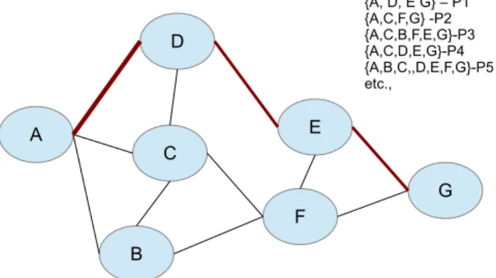
phenomena of networks: (i) a flow takes a path, (ii) the paths are deterministic set (all source destination paths are known a-priori) and (iii) multiple flows can take the same path. Therefore, for routing the packets we need to just identify the path for a flow and assign all the packets of the flow to this path. This association between the flow and the path is achieved through the PT. A simple path descriptor is shown in fig. 2.
Fig. 2: Sample Graph and the different paths
It should be noted that an all-pairs algorithm such as DFS can be used to obtain all the paths between source and destina-tion. However, this can be troublesome for larger graphs as this can lead to path explosion. The number of paths between all-pairs grows exponentially with the number of nodes and links found in the network. However, in practical implementation the number of paths are well below the theoretical limit and are manageable with the limited resources. Although current state of the art exploits ‘multi-path’ that captures multiple non-loopable routes between a pair or source and destination, yet they are deterministic. Further DC environment employs hierarchical network where the number of source-destination switches are significantly lower than the number of end machine and the flows. For the example network considered in Section II, the number of switches and the routable paths are much lower than the number of flows (order of several
Fig. 3: FLOW to PATH mapping
millions). Therefore, by using the PT, we map multiple flows to a path. The flow table now consists of entries having PT and each PT is associated with a specific action. It should be noted that we do not specify the action through our approach or change the action part but only use identity combining multiple flows to a path. In the core switch flow table, the flow entry can be reduced to the size of the PT and associated actions.
Once packets reach the destination switch, the packets have to be forwarded to the right port on which the end machine is connected. While the destination MAC address can be utilized for this purpose, the edge switches have to maintain a separate lookup table consisting of the (MAC + VLAN) to identify the operations for the packets. This can be overcome by associating the FT that uniquely identifies the flow among the packets. Thus FT provides the association between the packets of the flow and the flow tuple. It is simply a numeric identifier for identifying the flows uniquely. Fig. 3 shows the mapping of the flows to the PT and FT. Further, the flows might have different actions associated with them apart from normal 𝑅𝑂𝑈𝑇 𝐼𝑁𝐺. In such cases the FT can be used to identify the flows uniquely.
B. Realization of PATH and FLOW TAGS
SDN’s programming capability is leveraged to take ad-vantage of the 𝐹 𝑇 and 𝑃 𝑇. In order to realize the above architecture, the𝑃 𝑇 and the𝐹 𝑇 have to be generated, packet headers require this information to be embedded, look up entries in the flow table will now be populated using 𝑃 𝑇 and𝐹 𝑇. Several operations required for utilizing the𝐹 𝑇 and
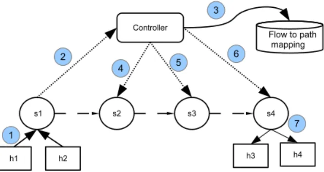
𝑃 𝑇 is simplified by the programming capabilities provided by the SDN networks. Figure 4 presents the different steps involved in realizing the end to end mechanism of utilizing
𝑃 𝑇 and𝐹 𝑇 using OpenFlow 1.2. OpenFlow specification for SDN specifically allows additional headers and information to be added to packets by using the PUSH operation. The end hosts remain unmodified and the entire set of operations are transparent to them. The hosts generate packets for different destinations. Let us assume that ℎ1 wants to send packets to ℎ2. ℎ1 generates packets toℎ2 (Step 1 in the Figure). In OpenFlow the first packet of a new flow arriving at an interface of a switch (in this case fromℎ1) is forwarded to the controller (Step 2 in the Figure) by the switch.
On receiving the packets, the controller generates a PT, FT pair for the flow and stores it in its local reference table (Step 3 in the Figure). In SDN, controller assumes logically
Fig. 4: Steps involved in achieving Tag-In-Tag
centralized role and therefore has the complete visibility of the network (nodes and paths) and decision capabilities on the flow and its packets. The controller decides the path for all packets of a flow. We assume that controller has existing path computation algorithm (eg.,spanning tree, shortest path etc.,) for determining the paths. Therefore, the controller chooses the path for the flow (𝑃 𝑇) and also records the𝐹 𝑇. The controller responds back to the Ingress switch (𝑠1in this case) with an OpenFlow action message consisting of the actions that pushes the 𝑃 𝑇 and 𝐹 𝑇 to the header of the packets belonging to that flow. Figure 3 shows sample packets that are output of the ingress switch 𝑠1 with the 𝑃 𝑇 and𝐹 𝑇 pushed on their headers and the packets encapsulated within.
The controller through OpenFlow messages can statically set the actions on all the switches for all the 𝑃 𝑇s for forwarding to specific port (Steps 4,5 in the Figure). For flow specific information the controller can provide matching rules against the 𝐹 𝑇 and specify action for all packets belonging to that specific flow. Leaving aside the ‘preamble’ and ‘start of delimiter’ fields in the Ethernet Frame, the 𝑃 𝑇 and 𝐹 𝑇 (if any) are pushed to the header. The ‘preamble’ and the ‘start of delimiters’ are used by the link layers for purpose of determining frame boundaries and are left intact. The original header and packet payload is encapsulated within this header. When a packet arrives at the intermediate switches, the 𝑃 𝑇 from the header is matched against the entries in the flow table. These switches do not perform any extra operation.
For the egress switches (S4, in this case), the controller sends a flow insert operation that contains the PT and FT and actions to remove them from the header of the packets.𝑃 𝑇 is no longer required as the packet has reached the destination switch.𝐹 𝑇 is further used to lookup for action that are specific for the packets of the flow at the egress switch. Once the actions are identified 𝑃 𝑇 and 𝐹 𝑇 are removed from the packet. The original packet that is encapsulated within the
𝑃 𝑇 and𝐹 𝑇 is forwarded to the port returned as the action associated with the FT. Thus, for the entire lifecyle expect for the ingress link and the egress link, only the𝑃 𝑇 and the𝐹 𝑇 are used for identifying the actions to be applied on the packet. In most cases, the TCAM entries need to store only the 𝑃 𝑇 for identifying the path the packet needs to take.
Computation of the 𝑃 𝑇 and 𝐹 𝑇: The combination of𝑃 𝑇 and𝐹 𝑇 should be a unique number that is required to identify the path. The numeric identifier for Tag-In-Tag is 24 bit long and therefore could identify224(around 16.8Million) unique flows with different path and flow diversity. There are two ways the unique identifier is being managed:(a) the flow ids can be recycled - once the flow is completed it can be used for a new flow. Also it has been shown in various studies the flows are short lived. This helps in reuse the flow ids. (b) Although the number of flows that can be supported by the TCAM is well above the practical numbers encountered during the experiments, in the worst case, live flows beyond
224would result in spilling on to the memory / software table.
C. Packet Forwarding Datapath: Micro-architectural changes
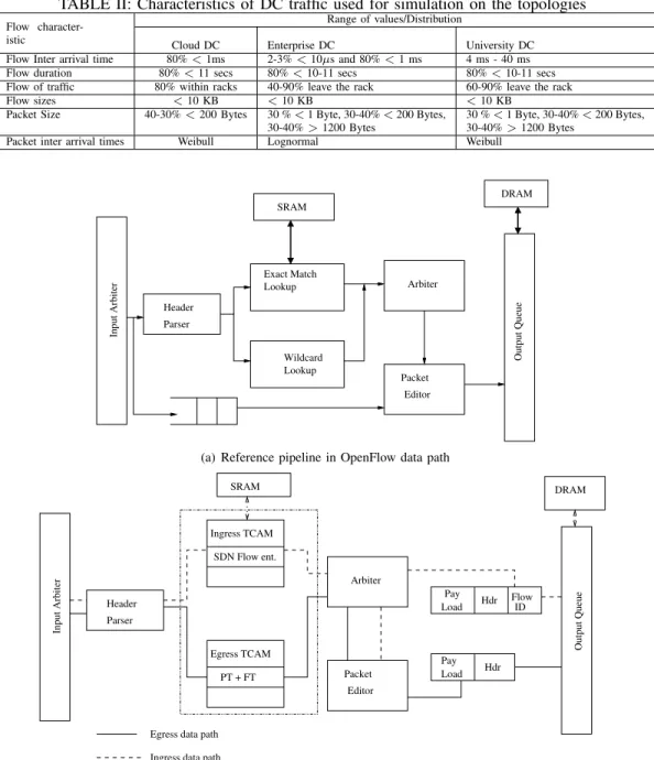
Fig. 5(a) illustrates the datapath described in OpenFlow implementation reference architecture [10]. Wild card lookup and exact match lookup are implemented using TCAMs. In fig. 5(b), modification in the TCAM datapath is shown for two separate modules. The datapath is split in to two TCAM, one for Ingress packets and the other for Egress packets. The hardware consists of a buffer that temporarily holds the packet along with the complete header. The assigned FT and PT is copied at the selected bits of the buffer (3 bytes following the frame delimiter, 1 byte for 𝑃 𝑇 and 2 bytes for𝐹 𝑇) and the packet is dispatched through the output port. The power consumption by these multiplexer are negligible compared to the hardware flow table operations. Packets arriving to the switching devices pass through the packet header parser which will now extract the ‘PT’ bits that is instructed through the bit selection logic.
Intermediate switches / core switches contain TCAM array that has entries with 𝑃 𝑇 and𝐹 𝑇. A query to these TCAMs will require fewer bits to search in parallel. These are the switches where we reap maximum benefit on TCAM power saving due to shorter header size.
An edge switch acts both as ingress for one set of flow and egress for another set of flows. When a packet arrives, the header either contains a PT + FT (at the egress) or a full header (at the ingress). This will require two flow tables, one with PT + FT and another with unmodified flow entries. We propose to use two separate TCAMs (Egress TCAM and Ingress TCAM as shown in Fig. 5(b)) each capable of storing half of the target number of entries. One TCAM stores the PT + FT and associated action and the other stores the complete flow entry with complete header along with action to PUSH (operation defined in OpenFLow specification) the PT + FT. The edge switch as directed by the controller either performs a PUSH operations (where the ‘PT + FT’ is inserted when the packet contains the full header) or POP (defined in OpenFlow specification) operation (for those packets containing PT + FT) where the extra information added by the ‘PUSH’ tag is removed. When a edge switch receives the packet, a special bit is used to identify whether the packet contains the PT + FT or the usual full header. Note that, for edge switches half of the TCAM hardware does not benefit from shorter tag.
Also, there are additional operations operations on TCAM to appropriately insert or remove tages. Hence the power gain on the edge switches is around 50% of that obtained from the core switches.
IV. ASSESSMENT ANDEVALUATION
Our objective is to assesses the following:(a) power saving in core and edge switches both due to the number of accesses and due to the nature of operations and (b) Space saving compared to a full 356-bit TCAM entries.
A. Simulation setting
We have chosen Data Center (DC) environment as Open-Flow is being adopted in DC networks, although our approach is not restricted to DC networks. In the absence of the fine grained flow level DC traces we simulate DC traffic by using the flow characteristics of real world DC’s shown in [5] [8]. For all our experiments we consider the switch-to-switch measurements. Table II presents the summary of the various network characteristics used in our simulation. We consider three configurations for our experiments: (a) L2 based switching device consisting of 60 bit (48 bit for source MAC + 12 bit for VLAN tag) flow entry, (b) OpenFlow standard based switching device consisting of 356 bits flow entries (15 tuple flow entries) and (c) and our Tag-In-Tag approach. We have considered three different topologies as shown in Fig. 6. Fat tree, 2-tier multi rooted tree, multi-tiered multi rooted tree represent diverse set of DC environments such as and Cloud DC, Enterprise DC and University DC respectively. Our simulator is implemented in Java. It simulates every event of packet arrival and performs the operation described for every packet. Here we integrate the simulation output from the TCAM power estimation tool. Flows are generated with the following tuple<flow id, src, destination,duration, startTime, endTime, flow sizes, packet sizes, flow length, flow of traffic,
start switch, end switch>. The start and the end switches are
dependent on the chosen topology.
B. Power Gain
Power dissipation by the switching fabric is a function of operations and the underlying hardware/software associated with performing these operations. We refer to pipeline ref-erence architecture provided in fig. 5(a) to study the power dissipation by different components of a switching device. Functionally it consists of a header parser, a input arbiter, lookup operations, and a mediator. Out of these functional units the most power expensive operations are those connected to the lookup operations (TCAM tables). A combination of SRAM and TCAM is typically used in modern day switches to store tables. Power is dependent on whether the operation is either a write or search operation. Therefore the total power consumption in a switch is given by equation 1
𝑃𝑠𝑤 = 𝑛𝑃 𝑎𝑐𝑘𝑒𝑡𝑠∑ 0 (𝐸𝑠−𝑠𝑒𝑎𝑟𝑐ℎ𝑁𝑙𝑜𝑜𝑘𝑢𝑝+𝐸𝑠−𝑤𝑟𝑁𝑖𝑛𝑠𝑒𝑟𝑡 +𝐸𝑡−𝑠𝑒𝑎𝑟𝑐ℎ𝑁𝑙𝑜𝑜𝑘𝑢𝑝+𝐸𝑡−𝑤𝑟𝑁𝑖𝑛𝑠𝑒𝑟𝑡) (1)
TABLE II: Characteristics of DC traffic used for simulation on the topologies
Flow character-istic
Range of values/Distribution
Cloud DC Enterprise DC University DC
Flow Inter arrival time 80%<1ms 2-3%<10𝜇s and 80%<1 ms 4 ms - 40 ms
Flow duration 80%<11 secs 80%<10-11 secs 80%<10-11 secs
Flow of traffic 80% within racks 40-90% leave the rack 60-90% leave the rack
Flow sizes <10 KB <10 KB <10 KB
Packet Size 40-30%<200 Bytes 30 %<1 Byte, 30-40%<200 Bytes, 30-40%>1200 Bytes
30 %<1 Byte, 30-40%<200 Bytes, 30-40%>1200 Bytes
Packet inter arrival times Weibull Lognormal Weibull
Editor Packet Arbiter Parser Header Exact Match Lookup Wildcard Lookup Input Arbiter Output Queue SRAM DRAM
(a) Reference pipeline in OpenFlow data path
Hdr Flow Load Pay ID Hdr Pay Load Editor Packet Arbiter SDN Flow ent. Ingress TCAM PT + FT Egress TCAM Parser Header Input Arbiter Output Queue
Ingress data path Egress data path
SRAM DRAM
(b) Modified data path, Ingress and Egress are shown in same diagram. Both TCAM modules are present for Edge switches. Core Switch has only One TCAM module with PT + FT
Fig. 5: Original data path and data path with micro-architectural changes to accommodate Ingress and Egress TCAM in the context of reference switch arch. in [10]
where 𝑁𝑙𝑜𝑜𝑘𝑢𝑝 and𝑁𝑖𝑛𝑠𝑒𝑟𝑡 are the number of lookup and insert operations performed per second,𝐸𝑠−𝑠𝑒𝑎𝑟𝑐ℎand𝐸𝑠−𝑤𝑟 are the energy associated with search and write of an entry in the SRAM, 𝐸𝑡−𝑠𝑒𝑎𝑟𝑐ℎ and 𝐸𝑡−𝑤𝑟 are the energy associated with search and write of an entry in TCAM. Equation 1 shows the power dissipation per switch and the total power dissipation for a flow will be equal to the power gains per switch times the number of switches visited.
Power gain on switches: We use TCAM modeling tool
available in [7] to observe the power consumption for different
sizes. This TCAM power model is widely used in the research community for measuring power consumption on the network devices [12]. In order to normalize the number of entries across the three categorize of switches (L2, SDN and Tag-In-Tag TCAM with entry compaction) we fix the number of flow entries across all the three to a arbitrary higher value and measure the power saving due to the bit line reduction. In our experiments we assume about 100000 entries and measure the power consumption for varying sizes of bit-line. We use traffic characteristics of 3 different DC environments (shown in Table
a1 e1 a2 e2 a3 e3 a4 e4 a5 e5 a6 e6 a7 e7 a8 e8 c1 c2 c3 c4 Core switches aggregation switches Edge switches
(a) Cloud DC - Fat Tree topology [11]
rc3 rc4
e1 e2 e3 e4 e5 e6 e7 e8 e9 e10 e11 e12 e13 e14 e15 e16 e17 e18 e19 e20 e21 e22 e23 e24 e25 e26 e27 e28 e29 e30 e31 e32 e33…e46
Core switching device Core switching device
e edge switch 2-tier hierarchical
topology
(b) Enterprise DC- Multi rooted 2 tier [5]
e22 e20 e26 e31
e5 e7 e29 e8 e9 e30 e11 e12 e34 e14 e15 e16 e19 e24 e32 c1 e18 e33 c2 e4 e10 e13 e27
Core switching device Core switching device
Edge/Middle of rack switches
(c) University DC- Multi rooted multi tier [5]
Fig. 6: DC topologies used for simulation
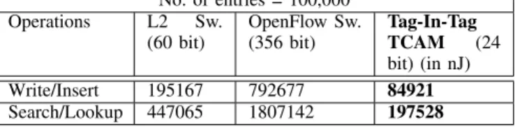
II) to simulate the TCAM power consumption. Table III shows the power consumption for different operations for Tag-In-Tag TCAM (with 24-bit line) in comparison with TCAM of L2 and SDN switches. As obvious, the power consumed to perform a write/insert operation with 24 bits is about 2.5 times lower than the 60 bit (L2 switch) and 14 times lower than the 356 bit entry (OpenFlow switch). A lookup/search operation with 24 bits consumes similarly lower power compared to the L2 and SDN switches.
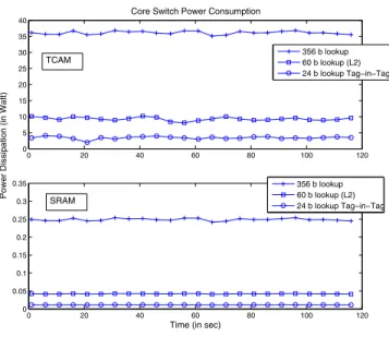
According to Equation 1 we need the number of packets that require lookup and insert operations. We fix the number of switches to one (either representing the core or a edge switch). The first packet of a Flow is considered to trigger a miss, resulting in a corresponding flow entry being inserted into the hardware table. Fig. 7 (a) presents the power consumption in Watt on the core switches and Fig. 7 (b) show the power consumption at edge switches for Enterprise and Univ DC’s. At the core switches, a L2 switching fabric would consume about 2.5 times more power and a OpenFlow enabled switch will consume about 12 times more compared to aTag-In-Tag
switch when the number of flows were observed in the range of 1200-1300 flows/sec. Therefore, in core switches Tag-In-Tag switch gives best power saving. This gain are lower in the edge switches as the power saving is obtained only for the egress flows. It can be seen that by employing modified TCAM entry approximately 80% of the power can be saved on the core and about 15% power saving in the edge switches.
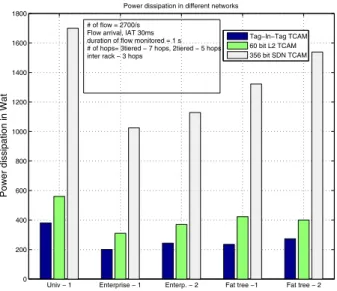
Power gain on flows:Fig. 8 shows the average case power
consumption for the flows considering different topology. On an average about 2700flows are generated in every second. For each of these flows we associate a path with probability determined by the nature of the flow of traffic in a particular DC environment and the number of switches as given in the topology. In the university topology savings can be achieved up to 35% compared to a 60 bit L2 switching device and about 80% compared to a 356 bit line SDN switching. This huge saving is due to the fact that in university data centers the amount of traffic that leaves the rack and travels through the network is about 80%. The saving is lesser (about 10% compared to L2 switching) in a enterprise DC setting as majority of the traffic (about 80%) is intra rack.
TABLE III: Power dissipation comparison for TCAM opera-tions: L2, OpenFlow and modified TCAM entry
No. of entries = 100,000 Operations L2 Sw. (60 bit) OpenFlow Sw. (356 bit) Tag-In-Tag TCAM (24 bit) (in nJ) Write/Insert 195167 792677 84921 Search/Lookup 447065 1807142 197528 C. Space saving
The number of bits associated with 𝑃 𝑇 is taken to be 8. It is observed that for all practical cases the total number unique paths in the fat-tree topology (used in our experiment) is around 100. Thus for the purposes of 𝑟𝑜𝑢𝑡𝑖𝑛𝑔, one would expect 8 bits for𝑃 𝑇 is sufficient for flow entries in the TCAM of the core/aggregate switches. The number of OpenFlow entries that can be saved in the 18 Mbit is around 50 k [4]. This implies that the number of misses to this table are of the order of several thousands. As mentioned before, the 𝐹 𝑇 can be stored using 16 bits. Therefore even with the combination of 𝑃 𝑇 and 𝐹 𝑇 the number of entries that could be accommodated is around 750 k entries. This is about 15 times increase in the number of entries that can be accommodated in the flow table using Tag-In-Tag approach.
V. RELATEDWORK
We classify the existing literature along three broad cat-egories and compare our work. They are: (a) algorithmic optimizations (b) reducing the amount of information stored in the high performance memory (c) architectural solutions. We provide a overview of the work along these three categories and compare our approach with them.
Algorithmic approaches for faster lookup’s:As an
alterna-tive to TCAM on the switch fabric, there have been several attempts to design fast algorithms for computing hashes [13], [14]. IPstash exploits the fact that full associativity is not necessary for IP-lookup [13]. In [14], authors propose an algorithm for longest prefix matching where prefixes are represented as trees and the tree is traversed according to a given key. These techniques reduce a set of arbitrary length prefixes to a predefined set of lengths. By this reduction, the number of depths in the prefix tree for traversal is reduced. We differentiate our work from these existing work along two
0 20 40 60 80 100 120 0 5 10 15 20 25 30 35 40
Core Switch Power Consumption
0 20 40 60 80 100 120 0 0.05 0.1 0.15 0.2 0.25 0.3 0.35
Time (in sec)
Power Dissipation (in Watt)
356 b lookup 60 b lookup (L2) 24 b lookup Tag−in−Tag 356 b lookup 60 b lookup (L2) 24 b lookup Tag−in−Tag TCAM SRAM
(a) Power consumption at the core switches
0 20 40 60 80 100 120 0 5 10 15 20 25
Edge Switch Power Consumption
0 20 40 60 80 100 120
0 0.1 0.2 0.3
Time (in sec)
Power Dissipation (in Watt)
50% 356b lookup+Tag−in−Tag 50% 60b lookup+Tag−in−Tag 50% 356b lookup+Tag−in−Tag 50% 60b lookup+Tag−in−Tag TCAM Power SRAM Power
(b) Power consumption at the edge switches
Fig. 7: Power consumption at the core and edge switches for Enterprise and Univ DC’s
dimensions. Firstly, these algorithms assume prefixes and pro-pose algorithms to optimize the traversal, storage and lookup of these prefixes. In SDN networks, there is lesser incentive (although not ruled out completely) for storing prefixes. SDN is designed to provide the flexibility of fine grained traffic management by defining the concept of ‘micro-flows’ by increasing the number of tuples. Secondly, these algorithms suffer from unacceptably slow updating (insert delete) of the forwarding table. In SDN as insert operations are likely to be dominant (1 in every three packets can result in a insert operation [15]) these algorithms are less scalable.
Reducing information in TCAM: Reducing the number of
entries in TCAM was considered in [16] [17]. In [17], an
algorithm have been propose to condense the flow table entries but retaining only those entries that subsume the other entries. In [16] a similar algorithm have been proposed for prefix expansion and aggregation. Our work is along the lines of reducing the information stored in the flow table. In our approach we exploit the capability of SDN to remove the redundant flow information used to identify the flow.
Architecture of TCAM:Architectural changes in the TCAM
design and usage have been proposed to the power consump-tion of TCAM’s. CoolCAM [18], EaseCAM [19], Routing table partitioning proposed in [20] are some the work that propose architectural changes. In CoolCAM, a bit selection forwarding engine architecture that exploits the fact that
prefixes in the core routing tables (less than 2%) are either very short or very long ( 24 bits) proposed. In EaseCAM [19], prefix aggregation and expansion techniques is used to compact the effective TCAM size in a router. An architectural extension have been proposed in [20] to organize TCAM blocks perform searches in parallel. Majority of the above work exploit the common prefixes that can be used to store per destination based/per port based wild card flow entries. As mentioned earlier, in SDN prefixes will have lesser preference and therefore will have limited adoption.
Univ − 1 Enterprise − 1 Enterp. − 2 Fat tree −1 Fat tree − 2 0 200 400 600 800 1000 1200 1400 1600 1800
Power dissipation in Wat
Power dissipation in different networks
Tag−In−Tag TCAM 60 bit L2 TCAM 356 bit SDN TCAM # of flow = 2700/s
Flow arrival, IAT 30ms duration of flow monitored = 1 s # of hops= 3tiered − 7 hops, 2tiered − 5 hops inter rack − 3 hops
Fig. 8: Power consumption in average case with different configuration. Univ-1: University 3 tier hierarchical topology, Enterp.-1: Enterprise 2 tier hierarchical topology, Enterp.-2: Enterprise 3 tier hierarchical topology, Fat tree-1: Fat tree topology (cloud) - interrack, Fat tree-2: Fat tree cloud 2 tier.
VI. CONCLUSIONS
In an attempt to have combined gain on power and space optimization we have identified TCAMs as an optimization tar-get. We propose modified TCAM architecture in the context of SDN that helps removal of redundancy stored in the TCAMs. Flows are generally used to classify a packet and perform op-erations specific to flows. We show that for classifying packets, the information in the flow entry can be condensed to just the size of unique flows. This provides significant reduction in the size of the flow entries (for OpenFlow implementation) which in turn yields about 80% reduction in power dissipation for core switches.
ACKNOWLEDGMENT
Most of the work was done while the first author was affiliated to IIIT-Delhi. Authors would like to thank IIIT-Delhi for providing laboratory support to conduct the experiments.
REFERENCES
[1] M. Lee, S. Goldberg, R. R. Kompella, and G. Varghese, “Fine-grained latency and loss measurements in the presence of reordering,” in Proceedings of the ACM SIGMETRICS joint international conference on Measurement and modeling of computer systems, ser. SIGMETRICS ’11. New York, NY, USA: ACM, 2011, pp. 329–340.
[2] J. Mudigonda, P. Yalagandula, J. Mogul, B. Stiekes, and Y. Pouffary, “Netlord: a scalable multi-tenant network architecture for virtualized datacenters,” SIGCOMM Comput. Commun. Rev., vol. 41, no. 4, pp. 62–73, Aug. 2011. [Online]. Available: http://doi.acm.org/10.1145/2043164.2018444
[3] N. McKeown, T. Anderson, H. Balakrishnan, G. Parulkar, L. Peterson, J. Rexford, S. Shenker, and J. Turner, “Openflow: enabling innovation in campus networks,”SIGCOMM Comput. Commun. Rev., vol. 38, no. 2, pp. 69–74, mar 2008.
[4] A. R. Curtis, J. C. Mogul, J. Tourrilhes, P. Yalagandula, P. Sharma, and S. Banerjee, “Devoflow: scaling flow management for high-performance networks,”SIGCOMM Comput. Commun. Rev., vol. 41, no. 4, pp. 254– 265, aug 2011.
[5] T. Benson, A. Akella, and D. A. Maltz, “Network traffic characteristics of data centers in the wild,” inProceedings of the 10th annual conference on Internet measurement, 2010, pp. 267–280.
[6] K. Rajan and R. Govindarajan, “A novel cache architecture and place-ment framework for packet forwarding engines,”IEEE Trans. Comput., vol. 58, no. 8, pp. 1009–1025, aug 2009.
[7] B. Agrawal and T. Sherwood, “TCAM Delay and Power Model,” http://www.cs.ucsb.edu/ arch/mem-model/.
[8] S. Kandula, S. Sengupta, A. Greenberg, P. Patel, and R. Chaiken, “The nature of data center traffic: measurements & analysis,” inProceedings of the 9th ACM SIGCOMM conference on Internet measurement con-ference, 2009, pp. 202–208.
[9] R. Niranjan Mysore, A. Pamboris, N. Farrington, N. Huang, P. Miri, S. Radhakrishnan, V. Subramanya, and A. Vahdat, “Portland: a scalable fault-tolerant layer 2 data center network fabric,”SIGCOMM Comput. Commun. Rev., vol. 39, no. 4, pp. 39–50, aug 2009.
[10] J. Naous, D. Erickson, G. A. Covington, G. Appenzeller, and N. McK-eown, “Implementing an openflow switch on the netfpga platform,” in Proceedings of the 4th ACM/IEEE Symposium on Architectures for Networking and Communications Systems, ser. ANCS ’08. New York, NY, USA: ACM, 2008, pp. 1–9.
[11] A. Greenberg, P. Lahiri, D. A. Maltz, P. Patel, and S. Sengupta, “Towards a next generation data center architecture: scalability and commoditiza-tion,” inProceedings of the ACM workshop on Programmable routers for extensible services of tomorrow, ser. PRESTO ’08. New York, NY, USA: ACM, 2008, pp. 57–62.
[12] B. Agrawal and T. Sherwood, “Modeling TCAM power for next gen-eration network devices,” inProc. of IEEE International Symposium on Performance Analysis of Systems and Software (ISPASS), Austin, TX, Mar 2006.
[13] S. Kaxiras, “Ipstash: A set-associative memory approach for efficient ip-lookup,”IEEE Infocom, pp. 992–1001, 2005.
[14] M. Waldvogel, G. Varghese, J. Turner, and B. Plattner, “Scalable high speed ip routing lookups,” 1997.
[15] J. C. Mogul, J. Tourrilhes, P. Yalagandula, P. Sharma, A. R. Curtis, and S. Banerjee, “DevoFlow: cost-effective flow management for high performance enterprise networks,” in Proceedings of the Ninth ACM SIGCOMM Workshop on Hot Topics in Networks, ser. Hotnets ’10. New York, NY, USA: ACM, 2010, pp. 1:1–1:6.
[16] V. Ravikumar and R. N. Mahapatra, “TCAM architecture for ip lookup using prefix properties,” IEEE Micro, vol. 24, no. 2, pp. 60–69, mar 2004.
[17] H. Liu, “Routing table compaction in ternary cam,”IEEE Micro, vol. 22, no. 1, pp. 58–64, jan 2002.
[18] F. Zane, G. Narlikar, and A. Basu, “Coolcams: Power-efficient TCAMs for forwarding engines,” inIN IEEE INFOCOM, 2003, pp. 42–52. [19] V. C. Ravikumar, R. N. Mahapatra, and L. N. Bhuyan, “Easecam: An
energy and storage efficient TCAM-based router architecture for ip lookup,”IEEE Trans. Comput, vol. 54, p. 2005, 2005.
[20] N.-F. Tzeng, “Routing table partitioning for speedy packet lookups in scalable routers,”IEEE Trans. Parallel Distrib. Syst., vol. 17, no. 5, pp. 481–494, 2006.