3D analysis of thermal and stress evolution during laser cladding of bioactive glass coatings
Michal Krzyzanowski1,2, Szymon Bajda2, Yijun Liu3, Andrew Triantaphyllou3, W. Mark Rainforth1 and Malcolm Glendenning4
1 The University of Sheffield, Department of Materials Science and Engineering, Mappin
Street, Sheffield S1 3JD, UK;
2 AGH University of Science and Technology, Mickiewicza 30, Krakow 30-059, Poland; 3 MTC Ltd, Ansty Park, Coventry CV7 9JU, UK;
4 Glass Technology Services Ltd., 9 Churchhill Way, Chapeltown, Sheffield S35 2PY, UK
Corresponding author: Michal Krzyzanowski, e-mail: [email protected]
Abstract
Thermal and strain-stress transient fields during laser cladding of bioactive glass coatings on the Ti6Al4V alloy basement were numerically calculated and analysed. Conditions leading to micro-cracking susceptibility of the coating have been investigated using the finite element based modelling supported by experimental results of microscopic investigation of the sample coatings. Consecutive temperature and stress peaks are developed within the cladded material as a result of the laser beam moving along the complex trajectory, which can lead to micro-cracking. The preheated to 500oC base plate allowed for decrease of the laser power and lowering of the cooling speed between the consecutive temperature peaks contributing in such way to achievement of lower cracking susceptibility. The cooling rate during cladding of the second and the third layer was lower than during cladding of the first one, in such way, contributing towards improvement of cracking resistance of the subsequent layers due to progressive accumulation of heat over the process.
Keywords: thermal and stress transient analysis; additive manufacturing; finite element modelling; laser cladding; bioactive glass coatings
1. Introduction
Bioactive glasses, discovered by Hench and co-workers at the end of the 1960s, are among the most promising biomaterials for bone repair and reconstruction, mainly thanks to their ability to form interfacial bonding with bone due to high bioactivity index. The discovery opened a new era in the development of materials for use in medicine. A comprehensive review of the state of the art in bioactive glasses from the material technology point of view summarizing possibilities of adjusting their physical and chemical properties tailoring the glass composition for novel clinical applications is presented elsewhere [6]. Unfortunately, due to their brittleness and relatively poor mechanical properties, their clinical applications are limited to non-load bearing implants. Therefore, coating a mechanically tough substrate is an alternative to reduce the risk of early implant failure [7]. Successful manufacturing of bioactive glass and silicate glass-ceramic scaffolds by means of innovative additive manufacturing technologies promises an expansion of the different applications of such scaffolds, including also load-bearing sites [8].
The laser cladding technique is promising, since the deposition rate is good and the substrate is not exposed to high temperatures during processing. In spite of the observed crystallisation of the glass, coatings obtained via laser cladding preserve the bioactivity of the original glass [9]. However, due to brittleness of the coatings, micro-cracking susceptibility of the laser cladded layers represent a significant problem limiting a wider application of the technique. The micro-cracking has a deteriorating effect on mechanical properties, it can lead to spallation of the coatings from the base material. Generally, preheating of the base material prior to the coating is one of the discussed solutions applied to the different laser cladded materials, for example to Co–Mo–Cr–Si [2] or Fe–Cr–C–W [10] coatings. It was indicated that numerical modelling seems to be an effective tool to explain the cause of micro-cracking of the laser cladded metallic materials although the spectrum of the physical events involved are quite complex due to laser interaction with a multiphase environment, and also to high speed melting and solidification of the different materials, such as the base and coating materials. A numerical model based on finite element methodology was developed in this work and applied for analysis of the thermal and strain-stress distributions during laser cladding of bioactive glass coatings on the Ti6Al4V alloy basement. The effect of preheating of the basement on the cracking susceptibility is numerically analysed showing agreement with the results of microscopic investigation.
2. Bioactive glasses, glass-ceramics and implant coating techniques.
controlled reactivity in body solutions [15]. The reactivity of glasses in such solutions are strongly dependent on the glass composition. The chemical durability and reactivity along with several other properties can be adjusted by the glass composition. Mechanical strength and especially the ability to sustain a certain mechanical impact and loading are also very important properties. Although, mechanical properties are more dependent on the surface condition rather than composition of the glass. It has been shown that the choice of the glass composition for a specific application should be based on an extensive and reliable knowledge on the influence of all components on the most relevant properties of the glass considering both the manufacture and the final application of the product [16].
A bioactive glass coating on a metal substrate plays a threefold role, namely, bonding easily with bone, it protects the substrate from corrosion and protects tissues from corrosion products that potentially can induce systematic effects. It is known that such coating of bioinert metal implants increases bone-implant contact in the early growth period increasing primary implant fixation and reduce the risk early implant failure. The time-dependent surface modification that occurs in the consecutive steps upon implantation and starts already in a few hours have been described as the following [17]:
- Alkaline and alkaline earth ions of the glass are exchanged with the environmental H+ ions;
- Si-O-Si bonds are hydrolysed and new Si-OH bonds known as silanols are formed at the surface;
- Polycondensation of Si-OH bonds results in formation of silica gel-like surface layer; - Ca2+, PO43- and CO32- ions are adsorbed on the silica gel;
- Progressive mineralization, formation and crystallisation of hydroxycarbonate apatite (HCA) layer.
Moreover, the Si ions, progressively released after implantation promote the growth and osteogenic differentiation of primary osteoblasts [18], Si and Ca ions are able to promote the upregulation and activation of some genes in osteoprogenitor cells [19]. Nowadays, attention is growing on glasses obtained by sol-gel methods, which make it possible to fabricate bioactive glasses in a wider range of compositions unobtainable using conventional melting [20, 21]. The glasses manufactured by these methods assume an appropriate structure to promote precipitation of HCA in biological environment. They are also manufactured with controlled porosity making them extremely promising for different biomedical applications [22].
In spite of their enormous potential, bioactive glass and ceramic coatings are still the subject for research rather than wide applications. Even the coatings obtained using such well-established methods as enamelling, thermal spray or electrophoretic deposition and thin film techniques, are not clinically used yet and under extensive investigation both in vitro and in vivo. The main disadvantage of enamelling is the residual stresses, which arise due to the mismatch between the coefficients of thermal expansion (CTE) between the metal and the glass, which can be overcome by proper formulation of the glass composition or using a bond coat inserted between the coating and the substrate having an intermediate CTE [23, 24, 13*]. As an alternative, creating a multi-layered system or a functionally graded coating with smooth change in composition and thermomechanical properties may be applied [25, 26]. The use of nanosized additives, instead of micrometric HA powders, or γ-rays sterilisation are another ways to improve the performance of the composite coatings [24]. A list of relevant papers summarising different enamelled bioactive glass coatings is provided elsewhere [7].
substrate [29]. Electrophoretic deposition (EPD) is a reliable and inexpensive technique with high deposition rate allowing coating parts with a complex shape [30]. The thickness control and the use of nanopowder are much easier with EPD. The main limitation is that the substrate must be conductive or coated with a conductive film and after the deposition, a sintering stage is required to consolidate the coatings. There are also different types of thermal spray techniques, such as plasma spray (PS) and high velocity oxyfuel spray (HVOF) that might be suitable for deposition of biomaterials [31]. Although PS deposited bioactive glass coatings are not widely commercially used yet, they have been studied for many years [32]. The new high velocity suspension flame spray (HVSFS), as an evolution of HVOF for obtaining bioactive glass coatings is currently under investigation [33, 34]. In this process, the torch is modified to enable the direct injection of liquid suspensions instead of powders. Bioactive glass coatings produced by different thin film technologies have been investigated for a couple of decades [35]. As an example, the pulse laser deposition (PLD) showed that the composition of the final bioactive coatings is very close to that of original bioactive glasses. PLD coatings stimulate the formation of HCA in an acellular simulated body fluid and promote osteoblast adhesion and proliferation [36 - 38].
The laser cladding method using powder feeding progressively considered in biomaterials research as the surface treatment approach conducted to calcium phosphate and bioactive glass coatings on Ti alloys [39-41, 9]. Laser cladding has also been applied for processing 3D calcium phosphate parts and bioactive glass [42]. As an alternative approach, laser cladding can be used as a reactive deposition technique, in which HA bioceramic coatings are synthesized on titanium substrate using calcium carbonate and calcium hydrogen phosphate [43]. It has been shown recently and mentioned in introduction that the technique can be successfully used for S520 bioactive glass coating on Ti substrates [9]. Despite of the observed crystallisation of the bioactive glass, coatings produced via laser cladding show the bioactivity of the original glass. Although, much more research on application of laser cladding has to be done and the literature on this topic is rather scarce, the technique is very promising due to at least two of the following factors such as the high deposition rate and not exposing the substrate to high temperatures during processing.
3. Experimental procedure
irregular shaped particles of bioactive glass powder supplied by Glass Technology Services (GTS) Ltd.
Single and multiple layer coatings were made on Ti-6Al-4V base material. The multiple layer coatings were made continuously layer by layer without switching off the laser power with intention keeping the base material hot to reduce the thermal stress. The bioactive glass coated structure was then sectioned for metallurgical observations. A Hitachi TM3000 Desktop Scanning Electron Microscope (SEM) was used for observation of the interface structure in back-scattered electron mode for presence of porosities and cracks.
4. Mathematical model
The mathematical model has been developed with intention to study the transient temperature distribution and the strain-stress fields during laser cladding of bioactive glass powders on the metal substrate. Although, the model set up includes the cladded material and the base plate, the presented numerical analysis is focused mainly on the cladded layer. The input data for the numerical calculations were taken assuming the experimental conditions described in the previous section along with the corresponding material properties characterising the base plate and the powder to be melted. The laser radiation is considered as a volumetric heat source to be absorbed in a volume of a green body, as it is recognised elsewhere [44]. A Gaussian distribution of the heat flux in the radial direction and exponential decay in the depth direction is defined by the following equation:
z
R r Q
z r
Q o
exp 2 exp
) , ( 2 0 2 (1)
where Q(r, z) is the heat flux at point with coordinates (r, z); r is the radial and z is the vertical coordinate correspondingly, Ro is the radius of the laser beam on the top surface and α is the
absorption coefficient of the green body. Qo is the maximum peak flux defined by the following
equation:
d R Q
Q L
o 2
0
(2)
where QL is the laser power and d is the heat penetration depth. The base was the titanium alloy
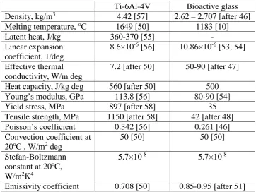
Ti-6Al-4V (Grade 5: 6% Al, 4% V, 0.2% O2 (max) and Ti as remainder) and the powder material was bioactive glass with the following nominal composition: 56.5% SiO2, 11.0% Na2O, 3.0% K2O, 15.0% CaO, 8.5% MgO, and 6.0% P2O5) [45]. The thermal and mechanical properties of both materials used for the modelling are presented in Table 1.
The property values of the materials shown in Table 1 with indications “after” were estimated based on available data for the materials of similar chemical composition. The effective thermal conductivity (ETC) of molten glass materials at high temperatures, k(T), is an important property affecting the glass melting and therefore the quality of the final laser cladded products. It is known that heat in the semi-transparent glass-melts is transferred by both conduction and radiation [46, 47]. The total heat flux can be expressed as the sum of a phononic and a radiative heat fluxes based on Fourier’s law. Due to lack of available data for ETC of bioactive glasses, considering the wide range of the relevant ETC values between 11-18 W/m deg and 35-80 W/m deg for the temperature T between 1100oC and 1500oC, the following expressions were used in the numerical analysis based on the effective thermal conductivity of soda-lime silicate glass-melts [47]:
0.021 14.61 T T
k (2)
0.025 17.32 T T
0.061 37.23 T T
k (4)
2.8 10 4 2 0.608 367.54
T T
T
k (5)
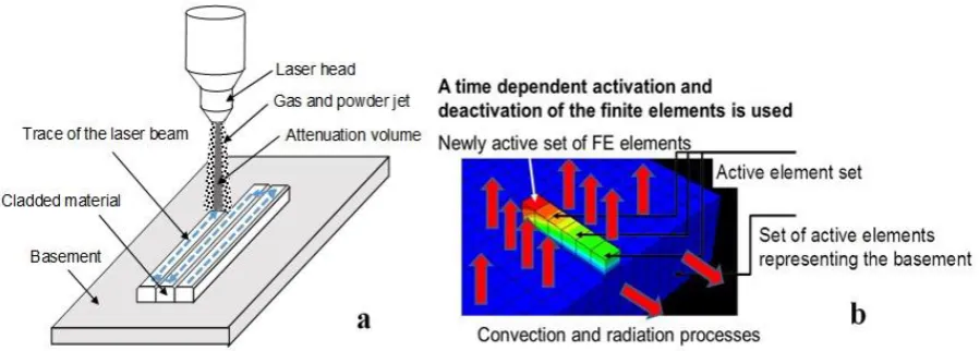
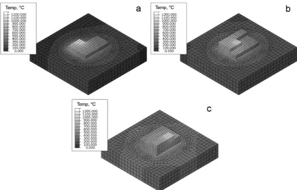
The finite element (FE) model setup was defined by the base and the coated material dimensions and also by sizes of single and multiple coating traces described in section 3. The number and sizes of the elements of the base and coating material for the different modelling cases were different and adjusted to achieve a reasonable computational time. It was assumed that the coating was located on the top surface of the base (Fig. 3a). The mathematical model used in the work is composed of two sets of 3-D elements within Abaqus/Standard FE software. The first set of the elements represents the titanium alloy base while the second one the increasing in time number of elements describing the melted bioactive powder material accumulated on the base plate surface in the form of a solid layer. In the numerical modelling, increase of the total amount of the cladded bioactive material was taken into account by a time-dependant activation of the finite elements (Fig. 3b). Initially, all the cladded beads have been meshed during the model configuration. Then, the cladded chunks are selectively activated during the analysis depending on the cladding speed. The simulation uses a sequentially coupled approach in which the temperature results from the thermal analysis are used in the followed stress analysis to calculate the thermal stress effects. The thermal analysis is performed to calculate the heat transfer that results from the thermal load of the moving laser beam and is run as a fully transient heat transfer analysis. The structural analysis uses the temperature results as the loading with the objective to determine transient stresses and strains induced in the heat affected zone (HAZ) during the cladding process.
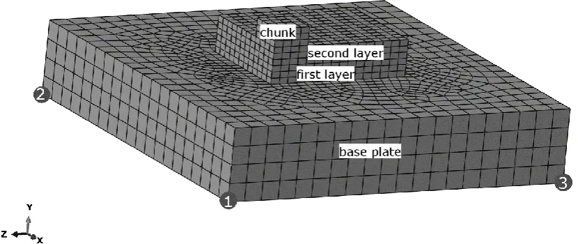
The initial temperatures of the base titanium alloy plate for the non-preheated and preheated cases were correspondingly assumed as 20 and 500°C. The initial temperature of the elements representing the cladded material at the moment of their activation was 20oC and it was immediately rising to high values under the influence of the absorbed laser radiation described in the model as the volumetric heat source. The heat source defined by eq. (1) was applied in the model using DFLUX subroutine. The ambient temperature was assumed as 20oC while the laser power, the diameter of the laser spot and the scanning speed were changed as follows: 60W - 120W, 1.2 mm and 5mm/s, respectively. The base plate was assumed 10 mm long, 10 mm wide and 2 mm thick consisting of 3620 8-node linear heat transfer brick elements. Three consecutive cladded layers were considered in the simulation in which each cladded chunk was 1 mm long, 1 mm wide and 0.5 mm thick consisting of 48 elements of the same type as the base plate (Fig. 4). The indicated in Fig. 4 three corner nodes of the base plate were constrained to prevent rigid body motion. Node 1 was fully constrained to move in three dimensions while constrains in Y and Z directions and in X and Y directions were placed correspondingly on node 2 and 3.
5. Results and discussion
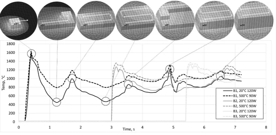
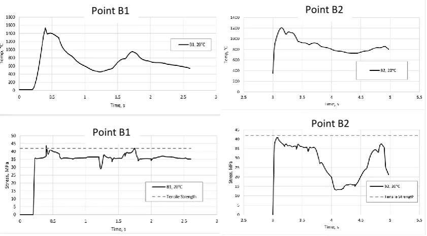
Fig. 7 shows the nodal temperature change calculated at the chosen points B1, B2 and B3 as the clad of bioactive glass is being deposited. There are two temperature curves for each point shown in the figure. The continuous curve corresponds to the cladding process onto the not preheated base plate with the initial temperature of 20oC using the laser power of 120W. The dashed curve represents the calculated temperature for the laser power of 90W but assuming the base plate preheated to 500oC. The temperature peaks shown in Fig. 7 correspond to the laser beam passage across the finite elements in which points B1, B2 and B3 are located within the first, second and the third cladding layer, correspondingly. The consecutive temperature peaks are developed as a result of the heat transfer from the laser beam moving along the trajectory shown in Fig. 5. The progress in the cladding simulation, in which several layers of bioactive glass are deposited onto the metal base without dilution of one into the other, shown at the top of Fig. 7 for several time moments corresponding to the consecutive temperature peaks.
The time difference between the first maximum and minimum peaks of the temperature at the point B1 is about 1s, which coincides with the completion of the first cladding track, when the laser beam is the most remote from the starting point. Then, the temperature at the point rises again when the beam approaches the point B1 completing the second (adjacent) track. The following peaks appear to be an effect of the thermal field generated by the laser beam passing other selected points B2 and B3. The temperature at the point B2 reaches its first maximum at the time moment of about 3s, at the completion of the fourth cladding track when the second layer is formed. It follows by its decrease with the laser beam moving away from the point repeating the trend observed earlier for the point B1. It can be noticed in Fig. 7, that the cooling rate was less for the point B2 than the one for the point B1. Similar temperature variations can be seen at the point B3, situated at the third cladding layer with even less cooling rate than it was observed at the points B1 and B2 (Fig. 7). It can also be noticed that the maximum temperature exceeds the melting temperature, which was assumed as 1183oC for the bioactive glass, at all three points. This indicates fulfilment of the melting condition for the coating during the cladding process. Lower cooling rate values were observed for the case of cladding on the preheated rather than not preheated base plate for all selected points. The shown differences in the cooling rate are more pronounced after the first (the highest) temperature peaks at each selected point. It has to be mentioned, that the melting condition has been fulfilled for a short time at the surface area of the bioactive glass and situated directly under the laser beam at the moment of cladding of the new material chunk (Fig. 8), i.e. at the moment of activation of the new group of the finite element corresponded to the deposited chunk of the bioactive material. This allowed for keeping the rest of the coating beneath the melting temperature, and in such way, cladding of the several tracks and layers.
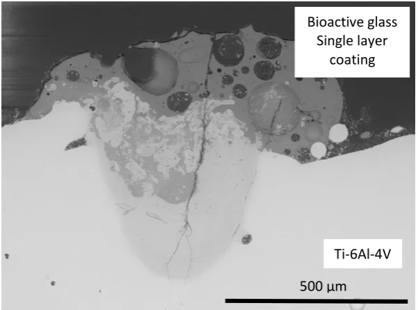
Variations of the transient temperature and equivalent stress predicted at the points B1 and B2 during cladding of the first and second layer onto the not preheated base plate are shown in Fig. 10. The dashed line in the figure corresponds to the tensile strength limit assumed for the cladded material as 42MPa. It can be noticed that while the maximum stress in the coating exceeds its strength limit for a short time during cladding of the first layer, its value is below the corresponding limit during cladding of the second layer of the glass. It explains increased cracking resistance during cladding of the subsequent layers of bioactive material. The numerical results are in good agreement with the experimental observations. Fig. 11 illustrates the cross section of the bioactive glass coating for the single track and single layer case when the metal base plate was not initially preheated. A large crack can be seen in the bioactive glass coating. Cracking of the glass coating in longitudinal direction is also observed experimentally during cladding of the single track on the not preheated base plate along with the transverse cracks. These longitudinal cracks result from stress localisations at the top curved areas of the coating. The predicted distribution of the equivalent stress on the top surface of the single track shows the area where the stress exceeds the tensile strength limit for the cladded material, and this area coincides with the place where the longitudinal crack was observed experimentally (Fig. 12). It has to be mentioned that the coating structure provided valuable information about the peak temperature distributions at the coated surface layer of the base plate. The cross sections, such as presented in Fig. 11, are characterised by the melted area, where the temperatures have exceeded the corresponding melting temperatures assumed in the model. The boundary of these areas were in good agreement with the predicted profiles of the relevant isotherms allowing for some verification of the model predictions along with comparing areas of the predicted stress localisations and experimentally observed cracking areas, such as presented in Fig. 12. Improvement of the cracking resistance of the subsequent second and third layer has been also noticed experimentally. In the case of triple layer but single track cladding, as it is shown in Fig. 13, the transverse cracks still exist in the first layer. However, cracks were not observed in the subsequent 2nd and 3rd layer of the coating. The obtained results favour the conclusion that the transient stresses generated within the bioactive material during laser cladding of subsequent layers are less than those generated during cladding of the first layer. They can be lower than the corresponding strength limit for the coating under the appropriate adjustment of the laser power. The observed effect is due to heat accumulation from cladding of the first layer not from the initial preheating of the base plate. In addition, the consecutive layers are deposited at the surface of glass having the same expansion coefficient. Therefore micro cracks formation is less expected in that case.
the whole process. It has to be mentioned that the peaks of the transient stress do not coincide with temperature peaks. The effect is clearly visible, for instance, in Fig. 16 showing the temperature and stress distribution predicted on the top surface of the base plate for the moment of the laser beam passage over the point T1. The equivalent stress developed within the material at the centre of the laser beam spot having the highest temperature is lower than the stress developed closer to the periphery zone, where the temperature is lower. The peaks of the transient thermal stress are developed around the laser heat spot due to thermal expansion of the material. They can affect neighbouring areas during cladding of multi tracks.
The edges of the material chunks reveal significantly higher temperature gradients at each moment of cladding increasing the probability of cracking at these areas. The calculated temperature gradients between top and bottom edges of three consecutive chunks of the cladded bioactive material are presented in Fig. 17a. The temperature gradients were calculated between the corresponding nodes of the top and bottom sides of the cladded chunks at three time moments when the centre of the laser beam spot was situated at the middle of the corresponding chunk. Fig. 17b illustrates the schematic representation of the nodes. The edges of the cladded bioactive glass chunks located closer to the start of the track reveal higher temperature gradients favouring their higher cracking susceptibility comparing with the later stages of the process.
As it has been observed experimentally, the cladded bioactive glass layers have largely remained amorphous. Partial crystallisation has been observed along the fusion line of the melt pool. Although presence of uncontrolled crystallisation may lead to some stress localisations within the corresponding areas of the coating, the observed minor spots of partial crystallisation are rather scarce and would not be playing a noticeable role in the crack initiation and propagation within the area.
6. Conclusions
(1)A numerical model based on FE methodology was developed and applied for analysis of the transient thermal and strain-stress distributions during laser cladding of bioactive glass coatings on the Ti6Al4V alloy basement. The input data for the numerical calculations were taken assuming the experimental setup. The number and sizes of the elements of the base and coating material for the different modelling cases were different and adjusted to achieve a reasonable computational time. The laser radiation was considered as a volumetric heat source. The model is composed of two sets of 3-D elements within Abaqus/Standard FE software representing the titanium alloy base and the melted bioactive powder material accumulated on the base plate surface in the form of a solid layer. The total amount of the cladded bioactive material was taken into account by time-dependant activation of the finite elements.
(3) The maximum transient stress in the coating exceeds its strength limit for a short time during cladding of the first layer. However, its value is below the corresponding limit during cladding of the second layer of the glass. It explains improvement of the cracking resistance during cladding of the subsequent layers of the bioactive material. The numerical results are in good agreement with the experimental observations.
(4) In the case of multiple tracks and multi layered coating on the not preheated base plate, the transverse cracks can be present in the region close to the base plate across tracks. Occasionally, the cracks can propagate to the top surface of the coating. The cracking during multiple track coating can occur when the laser beam thermally affects the earlier cladded adjacent track.
(5)The cracks originated in the cladded material can propagate into the surface layer of the not preheated base plate during cladding. However, the numerical results show no evidence of their origination within the metal base plate during the cladding process, as the predicted transient stress within the plate is below the tensile strength during the whole process route.
(6) The edges of the cladded bioactive material reveal significantly higher temperature gradients increasing the probability of cracking at these areas. The edges located closer to the start of the track reveal higher temperature gradients favouring their higher cracking susceptibility comparing with the later stages of the process.
Acknowledgements
The support of the EPSRC UK under grant EP/L505158/1, "Novel 3D Coating of Bioactive Glass and Metal Composites" and the National Science Centre Poland (grant no. DEC- 2013/09/B/ST8/00141) is greatly appreciated. The authors are particularly grateful for the input from JRI Orthopaedics Ltd, and also to Chris Holcroft and Dave Eustice from Glass Technology Services (GTS) Ltd.
References
1. Y.P. Kathuria, Some aspects of laser surface-cladding in the turbine industry, Surf. Coatings Technol., 2000, 132, 262– 269.
2. J. Przybyłowicz and J. Kusinski, Laser cladding and erosive wear of Co–Mo–Cr–Si coatings, Surf. Coatings Technol., 2000, 125, 13–18.
3. L. Sexton, S. Lavin, G. Byrne and A. Kennedy, Laser cladding of aerospace materials. J Mater Process Technol., 2002, 122, 63–68.
4. R.J. Furlong and J.F. Osborn, Fixation of hip prostheses by hydroxyapatite ceramic coatings. J. Bone Jt. Surg. Br., 1991, 73(5), 741-745.
5. K.A. Hing, S.M. Best, K.E. Tanner, W. Bonfield and P.A. Revell. Mediation of bone ingrowth in porous hydroxyapatite bone graft substitutes. J. Biomed. Mater. Res. A, 2004, 68, 187-200.
6. Bioactive glasses Materials, properties and applications, Eds. Heimo O. Ylänen, Woodhead Publishing Ltd, Cambridge, UK, 2011.
7. A. Sola, D. Bellucci, V. Cannillo and A. Cattini, Bioactive glass coatings: a review, Surface Engineering, 2011, 27 (8), 560-572.
9. R. Comesana, F. Quintero, F. Lusquinos, M. J. Pascual, M. Boutinguiza, A. Durán and J. Pou, Laser cladding of bioactive glass coatings, Acta Biomater., 2010, 6, 953– 961.
10. J. Choi, J. Mazumder, Synthesis of Fe–Cr–C–W using laser cladding technique, J Mater Sci., 1994, 29(17), 4460–4476.
11. H. Arstila, E. Vedel, L. Hupa and M. Hupa, Predicting physical and chemical properties of bioactive glasses from chemical composition. Part 2: devitrification characteristics, Glass Technology: European Journal of Glass Science and Technology, Part A, 49(6), 260-265.
12. L.L. Hench, Bioceramics: from concept to clinic, J. Am. Ceram. Soc., 1991, 74, 1487-1510.
13. L.L. Hench, Biomaterials: a forecast for the future, Biomaterials, 1998, 19, 1419-1423.
14. T. Kokubo, S. Ito, S. Sakka and T. Yamamuro, Formation of a high-strength bioactive glass-ceramic in the system MgO-CaO-SiO2-P2O5, J. Mater. Sci, 1986, 21, 536-540.
15. L. Hupa, K. Karlsson, M. Hupa and H.T. Aro, Comparison of bioactive glasses in vitro and in vivo, Glass Technology: European Journal of Glass Science and Technology, Part A, 2010, 51(2), 89-92.
16. E. Vedel, H. Arstila, H. Ylänen, L. Hupa and M. Hupa, Predicting physical and chemical properties of bioactive glasses from chemical composition. Part 1: viscosity characteristics. Glass Technology: European Journal of Glass Science and Technology, Part A, 49(6), 251-259.
17. L. L. Hench and J. Wilson, An Introduction to Bioceramics, World Scientific, Singapore, 1993.
18. B.I. Beletskii and N.V. Sventskaya, Silicon in living organisms and new generation biocomposite materials (review), Glass Ceram., 2009, 66, 104-108.
19. L.L. Hench, Genetic design of bioactive glass, J. Eur. Ceram. Soc., 2009, 29, 1257-1265.
20. N. Li, Q. Li, S. Shu and R. Wang, Preparation and charcterisation of macroporous sol-gel bioglass, Ceram. Int., 2005, 31, 641-646.
21. U. Vijayalakshmi, A. Balamurugan and S. Rajeswari, Synthethis and characterization of porous silica gels for biomedical applications, Trends Biomater. Rtif. Organs, 2005, 18, 101-105.
22. R.M. Almeida, A. Gama and Y. Vueva, Bioactive sol-gel scaffolds with dual porosity for tissue engineering, J. Sol-Gel Sci. Technol., 2009, DOI 10.1007/s10971-009-2134-8.
23. C.Y. Tang, C.P. Tsui, D.J. Janackovic and P.S. Uskokovic, Nanomechanical properties evaluation of bioactive glass coatings on titanium alloy substrate, J. Optoelectron. Adv. Mater., 2006, 8, 1194-1199.
24. S. Bharati, C. Soundrapandian, D. Basu and S. Datta, Studies on a novel bioactive glass and composite coating with hydroxyapatite on titanium based alloys: effect of γ-sterilization on coating, J. Eur. Ceram. Soc., 2009, 29, 2527-2535.
25. S. Foppiano, S.J. Marshall, E. Saiz, A.P. Tomsia and G.W. Marshall, Functionally graded bioactive coatings: reproducibility and stability of the coating under cell culture conditions, Acta Biomater., 2006, 2, 133-142.
27. M.H. Fathi and A. Doost Mohammadi, Bioactive glass nanopowder and bioglass coating for biocompatibility improvement of metallic implant, J. Mater. Process. Technol., 2009, 209, 1385-1391.
28. M.H. Fathi and A. Doost Mohammadi, Preparation and characterisation of sol-gel bioactive glass coating for improvement of biocompatibility of human body implant, Mater. Sci. Eng. A, 2008, A474, 128-133.
29. J. Gallardo, P. Galliano and A. Duran, Bioactive and protective sol-gel coatings on metals for orthopaedic prostheses, J. Sol-Gel Sci. Technol., 2001, 21, 65-74.
30. I. Corni, M.P. Ryan and A.R. Boccaccini, Electrophoretic deposition: from traditional ceramics to nanotechnology, J. Eur. Ceram. Soc., 2008, 28, 1353-1367. 31. H. Herman, S. Sampath and R. McCune, Thermal spray: current status and future
trends, MRS Bull., 2000, 25, 17-25.
32. C. Gabbi, A. Cacchioli, B. Locardi and E. Guadagnino, Bioactive glass coating: physicochemical aspects and biological findings, Biomaterials, 1995, 16, 512-520. 33. A. Killinger, M. Kuhn and R. Gadow, High-velocity suspention flame spraying
(HVSFS), a new approach for spraying nanoparticles with hypersonic speed, Surf. Coat. Technol., 2006, 21, 1922-1929.
34. G. Bolelli, V. Cannillo, R. Gadow, A. Killinger, L. Lusvarghi and J. Rauch, Microstructural and in vitro characterisation of high-velocity suspension flame sprayed (HVSFS) bioactive glass coatings, J. Eur. Ceram. Soc., 2009, 29, 2249-2257.
35. L. Torrisi and R. Setola, Thermally assisted hydroxyapatite obtained by pulse-laser deposition on titanium substrates, Thin Solid Films, 1993, 227, 32-36.
36. C. Berbecaru, H.V. Alexandru, A. Ianculescu, A. Popescu, G. Socol, F. Sima and I. Mihailescu, Bioglass thin films for biomimetic implants, Appl. Surf. Sci., 2009, 255, 5476-5479.
37. A.C. Popescu, F. Sima, L. Duta, C. Popescu, I.N. Mihailescu, D. Capitanu, R. Mustata, L.E. Sima, S.M. Petrescu and D. Janackovic, Biocompatable and bioactive nanostructured glass coatings synthesized by pulsed laser deposition: in vitro biological tests, Appl. Surf. Sci., 2009, 255, 5486-5490.
38. L. D’Alessio, R. Teghil, M. Zaccagnino, I. Zaccardo, D. Ferro and V. Marotta, Pulsed laser ablation and deposition of bioactive glass as coating material for biomedical applications, Appl. Surf. Sci., 1999, 138-139, 527-532.
39. F. Lusquiňos, J. Pou, J.L. Arias, M. Boutinguiza, M. Perez-Amor, B. León and F.C.M. Driessens, Production of calcium phosphate coatings on Ti6Al4V obtained by Nd:yttrium-aluminum-garnet laser cladding, J. Appl. Phys., 2001, 90, 4231-4236. 40. F. Lusquiňos, A. De Carlos, J. Pou, J.L. Arias, M. Boutinguiza, B. León, M.
Perez-Amor, F.C.M. Driessens, K. Hing, I. Gibson, S. Best and W. Bonfield, Calcium phosphate coatings obtained by Nd:YAG laser cladding: physico-chemical and biological properties, J. Biomed Mater. Res.; 2003, 64A, 630-637.
41. M. F. Lusquiňos, J. Pou, M. Boutinguiza, F. Quintero, R. Soto, B. León and M. Pérez-Amor, Main characteristics of calcium phosphate coatings obtained by laser cladding, Applied Surface Science, 2005, 247, 486–492.
42. R. Comesaňa, F. Lusquiňos, J. del Val, M. López-Álvarez, F. Quintero, A. Riveiro., M. Boutinguiza, A. De Carlos, J.R. Jones, R.G. Hill and J. Pou, Three-dimentional bioactive glass implants fabricated by rapid prototyping based on CO2 laser cladding, Acta Biomaterialia, 2011, 7, 3476-3487.
44. P. Kongsuwan, G. Brandal and Y.L. Yao, Laser induced porosity and crystallinity modification of a bioactive glass coating on titanium substrates, Journal of Manufacturing Science and Engineering, 2015, 137(3), 031004-031004-12, DOI: 10.1115/1.4029566.
45. S. Lopez-Esteban, E. Saiz, S. Fujina, T. Oku, K. Suganuma and A. P. Tomsia, Bioactive glass coatings for orthopaedic metallic implants, J. of the European Ceramic Society, 2003, 23, 2921-2930.
46. A.K. Srivastava, R. Pyare and S.P. Singh, Elastic properties of substituted 45S5 Bioactive Glasses and Glass – Ceramics, Int. J. Scientific & Engineering Research, 2012, 3(2), 1-13, ISSN 2229-5518.
47. L. Pilon, F. Janos and R. Kitamura, Effective thermal conductivity of soda-lime silicate glassmelts with different iron contents between 1100oC and 1500oC, J. Am. Ceram. Soc., 2014, 97(2), 442-450.
48. L.-Chr. Gerhardt and A.R. Boccaccini, Bioactive glass and glass-ceramic scaffolds for bone tissue engineering, Materials, 2010, 3, 3867-3910, DOI: 10.3390/ma3073867.
49. E.D. Zanotto, A bright future for glass-ceramics, American Ceramic Society Bulletin, 2010, 89 (8), 19-27.
50. J. Yang, Sh. Sun, M. Brandt and W. Yan, Experimental investigation and 3D finite element prediction of the heat affected zone during laser assisted machining of Ti6Al4V alloy, Journal of Materials Processing Technology, 2010, 210, 2215-2222. 51. http://www.engineeringtoolbox.com/emissivity-coefficients-d_447.html
52. E. E. Anderson and R. Viskanta, Effective Thermal Conductivity for Heat Transfer Through Semitransparent Solids, J. Am. Ceram. Soc., 1973, 56(10), 541–546. 53. E. Saiz, M. Goldman, J. M. Gomez-Vega, A. P. Tomsia, G. W. Marshall, S. J.
Marshall, In vitro behavior of silicate glass coatings on Ti6Al4V, Biomaterials, 2002, 23 (17), 3749-3756.
54. J. M. Gomez-Vega, E. Saiz, A. P. Tomsia, G. W. Marshall, S. J. Marshall, Bioactive® glass coatings with hydroxyapatite and Bioglass particles on Ti-based implants. 1. Processing, Biomaterials, 2000, 21, 105-111.
55. G. Chassaing, A. Pougis, S. Philippon, P. Lipinski and J. Meriaux, Experimental and numerical study of frictional heating during rapid interactions of a Ti6Al4V tribopair, Wear, http://dx.doi.org/10.1016/j.wear.2015.09.013
56. F. Ducobu, E. Rivière-Lorphèvre, E. Filippi, Numerical contribution to the comprehension of saw-toothed Ti6Al4V chip formation in orthogonal cutting, International Journal of Mechanical Sciences, 81, 2014, 77-87.
57. S. M. Ratchev, S. M. Afazov, A. A. Becker, S. Liu, Mathematical modelling and integration of micro-scale residual stresses into axisymmetric FE models of Ti6Al4V alloy in turning, CIRP Journal of Manufacturing Science and Technology, 4, 2011, 80-89.
Table 1. Thermal and mechanical properties of the metal base and bioactive powder used for the modelling.
Ti-6Al-4V Bioactive glass Density, kg/m3 4.42 [57] 2.62 – 2.707 [after 46] Melting temperature, oC 1649 [50] 1183 [10]
Latent heat, J/kg 360-370 [55] -
Linear expansion coefficient, 1/deg
8.6×10⁻⁶ [56] 10.86×10⁻⁶ [53, 54]
Effective thermal conductivity, W/m deg
7.2 [after 50] 50-90 [after 47]
Heat capacity, J/kg deg 560 [after 50] 500 Young’s modulus, GPa 113.8 [56] 80-90 [54]
Yield stress, MPa 897 [after 58] 35
Tensile strength, MPa 1150 [after 58] 42 [after 48] Poisson’s coefficient 0.342 [56] 0.261 [46] Convection coefficient at
20oC , W/m2 deg
50 [50] 50 [50]
Stefan-Boltzmann constant at 20oC, W/m2K4
5.7×10⁻⁸ 5.7×10⁻⁸
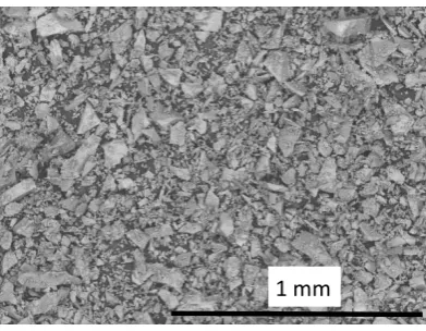
Fig. 1 Irregular shaped particles of bioactive glass powder used for laser cladding.
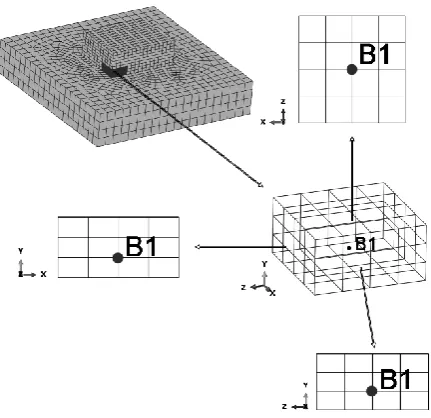
Fig. 6 Location of the point within the group of the finite elements representing the cladded material
Cladded material
The base plate
Fig. 9 The variation of temperature with time at points B1, B2 and B3 within the cladded material predicted during laser cladding of bioactive glass for the different initial temperatures of the base plate and the following values of the laser power: 120W and 60W.
Point B1
Point B1
Point B2
Point B2
Fig. 11 SEM image showing cross section of the bioactive glass coating on not preheated Ti-6Al-4V base plate (single track).
500 µm Ti-6Al-4V Bioactive glass
2 mm Stress localisation (left)
Longitudinal crack (right)
1 mm Bioactive glass
Triple layer coating
Ti-6Al-4V
2 mm Ti-6Al-4V
Bioactive glass Multi-layered
coating
a
b
c
Ti-6Al-4V
Fig. 15 The equivalent stress predicted at the surface layer of the base plate (points T1 and T2) during laser cladding of the bioactive glass for the following parameters: laser power 120W, the initial temperature of the base plate 20oC and 500oC.
a
b
b
Cladding direction
Start of the track
Chunk 1 Chunk 2 Chunk 3
a
![Fig. 2 Temperature dependence of the effective thermal conductivity of the different glass-melts used in the numerical analysis [after 47]](https://thumb-us.123doks.com/thumbv2/123dok_us/1010004.1600907/16.595.146.463.87.403/temperature-dependence-effective-thermal-conductivity-different-numerical-analysis.webp)