Nonlinear Processes in Geophysics (2002) 9: 165–170
Nonlinear Processes
in Geophysics
c
European Geophysical Society 2002
The Karlsruhe Dynamo Experiment
U. M ¨uller and R. Stieglitz
Received: 23 October 2001 – Accepted: 6 December 2001
Abstract. It has been shown theoretically in the past that homogeneous dynamos may occur in electrically conduct-ing fluids for various vortical velocity fields. Roberts (1972) investigated spatially periodic, infinitely extended fields of vortices which Busse (1978, 1992) confined to a finite cylin-drical domain. Based on Busse’s vortex arrangement a con-ceptual design for an experimental homogeneous dynamo has been developed and a test facility was setup at the Forschungszentrum Karlsruhe. The first experiments demon-strated that permanent dynamo action can be generated in a cylindrical container filled with liquid sodium in which by means of guide tubes counterrotating and countercurrent spi-ral vortices are established. The dynamo is self-exciting and the magnetic field saturates at a mean value for fixed super-critical flow rates. The instantaneous magnetic field fluctu-ates around this mean value by an order of about 5%. As predicted by theory the mode of the observed magnetic field is non-axisymmetric. In a series of experiments a phase- and a bifurcation diagram has been derived as a function of the spiral and axial flow rates.
1 Introduction
Today it is generally accepted that planetary magnetic fields originate from vortex-type flow of electrically conducting fluids. From general physical and physico-chemical consid-erations it has been concluded that in rotating planets vorti-cal flow is generated in a liquid core by thermal and solutal convection (see, e.g. Braginsky and Roberts, 1995). Busse and Carrigan (1976) have demonstrated experimentally that in rapidly rotating spherical shells a convective flow driven by density gradients may form a columnar vortex pattern typ-ically oriented parallel to the rotation axis.
Naturally the question arises, whether a regular spatial ar-rangement of spiral vortices is capable to amplify small
mag-Correspondence to: R. Stieglitz
netic seed fields to a finite intensity, depending on the con-version rate of mechanical into electrical energy and the dis-sipation rate of the dynamo system. Roberts (1970, 1972) studied analytically dynamo action associated with an in-finitely extended and with regard to two directions spatially periodic velocity field characterized by a velocity scale u and a wavelength 2a. Together with the magnetic diffusiv-ity of the fluidλthese parameters can be combined in a di-mensionless group, the magnetic Reynolds numberRem =
(u·a)/λ, to characterize the system. Roberts shows that “almost all spatially periodic velocity distributions in a ho-mogeneous conducting fluid will generate dynamo action for almost all values of the conductivity”. Busse (1978, 1992) modified Roberts’ dynamo model by introducing a second larger length scale, say the radius r0(see Fig. 1a). He as-sumes a/r0 1 , and using a scale separation method he derives approximate conditions for the onset of netic self-excitation and the solution for the associated mag-netic field pattern. Introducing magmag-netic Reynolds numbers for the mean axial and the mean azimuthal velocity com-ponents (uC, uH) in the form RemC = (uC · a)/λ and
RemH =(uH·d)/λhe finds as a condition for the occurence
of an axisymmetric field,
RemC·RemH ≥
32 π
"
1+
3.83
π ·
d r0
2#
, (1)
166 U. M¨uller and R. Stieglitz: The Karlsruhe Dynamo Experiment
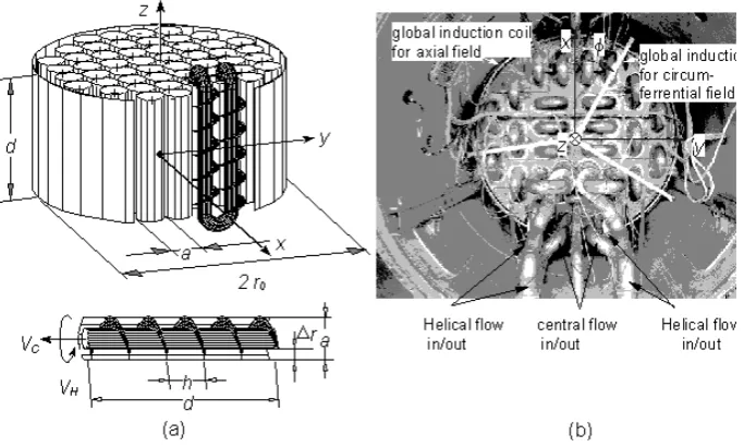
Fig. 1. Conceptional engineering design for a dynamo test module according to Stieglitz and M¨uller (1996), (a) vortex generator and vortex generator assembly, (b) Photograph of the operational Karlsruhe Dynamo test module. A reference coordinate system is marked.
VHelical, which are related to the axial and azimuthal velocties uCanduHof the model flow.
In order to assess constraints of Relationship (1) Tilgner (1997) and R¨adler et al. (1996, 1998) performed more detailed calculations for technical geometries which ac-count for realistic matching conditions for the magnetic field from the inside to the outside domain of the dynamo module and also for the sodium filled zones at rest within the mod-ule as well as for connecting bends and pipes. As a result of their calculations it turned out that the lowest critical mag-netic Reynolds numbersRemC andRemH are obtained for
the lowest non-axisymmetric modem=1 rather than for the axisymmetric modem=0 of the magnetic field. The results of R¨adler et al. (1996, 1998) and Tilgner (1997) will be used for comparison with experimental results.
2 Experimental facility
The dynamo test module was designed under the viewpoint that for an available pumping capacity a sufficient flow rate for a self-excitation of a magnetic field can be achieved. This required a fluid dynamic optimization of the vortex gener-ators with regard to the pressure losses. A semi-technical sketch of the module and the coordinate system with its ori-gin located in the module’s center is shown in Fig. 1. In a test series a pressure drop correlation for the flow in the helical ducts was derived containing the following param-eters: Z the number of vortex generators, χ the number of windings per vortex generator, rm the mean radius of
the helical duct, 1r the distance between inner and outer tube, h the height of each winding and ρ the density of the liquid sodium. Using Relation (1) and the derived pres-sure drop correlation the optimization results in critical mag-netic Reynolds numbersRemof less than 10 or in technical
terms in volumetric flow rates required for self-excitation of VCentral =VHelical =115−143 m3/h for the following ge-ometrical dimensions: Z = 52, a = 0.21m, h = 0.19m, 1r=0.055m, r0=0.85m, d =0.703mandχ =3.7. The module is entirely fabricated of stainless steel. The module is placed in a room in which the average magnetic field strength is less than 0,5 Gauss. A power test of the sodium induction pumps showed that the magnetic perturbations produced by them do not affect the locations where the measurements of the dynamo action are conducted. The dynamo’s magnetic field is measured by six Hall-probes resolving less than 0.5 Gauss and, moreover, sensed by six global induction coils. The sodium volumetric flow rate for the test module is pro-vided by MHD pumps in three independent loop systems and is measured by electromagnetic (EM) flow meters in each loop which are calibrated to have errors less than 0.3%. The pressure drop across the module in each of the three inde-pendent flow channels were measured by using sensitive ca-pacitance pressure gauges with an accuracy of ±5·102Pa. A more detailed description of the experimental set-up and the sodium systems may be taken from a report by Stieglitz and M¨uller (1996). Dynamo action in this test facility was demonstrated in late 1999 and first experimental results have been published by Stieglitz and M¨uller (2001). Here we present some results from recent experiments.
3 Results
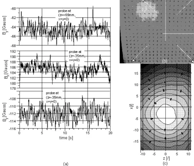
Figures 2b–d show time series of the signals of six Hall-probes located in a tube on the center axis of the module at different positions. The gradual increase of the volumetric flow rates in the central duct (VCentral) and the helical chan-nels (VHelical,1, VHelical,2) is shown in Fig. 2a as a function of
U. M¨uller and R. Stieglitz: The Karlsruhe Dynamo Experiment 167
Fig. 2. (a) Time averaged signals of the volumetric flow rates in the central (VCentral) and the helical ducts (VHelical,1, VHelical,2). (b)–(d) Corresponding signals of three Hall probes (z= −135 mm,z= −35 mm andz=65 mm) indicating the threeB-field componentsBx(b),
By(c) andBz(d) according to the coordinates defined in Fig. 1b.
step-like increase of two components of the magnetic field inx and y direction. These figures demonstrate the pres-ence of a homogeneous dynamo producing a mean magnetic field of the order of 80 Gauss. Moreover, each increase of the volumetric flow rate to the next level is followed by a corresponding increase of the magnetic field to another satu-ration level. There is a delayed response of the B-field to the controlled variation of the volumetic flow of about 2–3 times the variation interval of the flow. It is to be noted here that no additional external magnetic field was supplied to the test module during this run aside from the ambient seed field of less than 0.5 Gauss.
Two other Hall probes sensitive to thez-component of the magnetic field did not record signals of comparable inten-sity. Figure 2d shows the corresponding axial magnetic field intensity in the center bore of the module. The relatively low intensity of the axial field component together with the high intensities of the other field components indicates the non-axisymmetric nature of the generated magnetic field and thus supports the theoretical predictions of Tilgner (1997) and R¨adler et al. (1996, 1998). Their calculations show that for the mean field the non-axisymmetric mode m = 1 is preferred. Another experimental evidence for the presence
of the modem =1 is shown by the photograph in Fig. 3b and the isoline graph in Fig. 3c. An array of compass nee-dles (located in the planey =1.5m) was photographed at a super-critical state of the dynamo. The photograph indicates a source (sink) of lines of force near the y-axis emerging from the center of the module.
The graph in Fig. 3c shows the normal component of the B-field on the same plane measured by a “carry on” Gauss meter. The isolines clearly indicate the quasi-dipole axis to be perpendicular to the axis of the module. Moreover, the quasi-dipole axis is slightly shifted towards the fourth quad-rant of the plane. Whether this effect reflects small techni-cal non-symmetries of the module or generic non-symmetic properties of the velocity field has to be shown by further analyses.
168 U. M¨uller and R. Stieglitz: The Karlsruhe Dynamo Experiment
Fig. 3. (a) Simultaneously recorded time series of different Hall-probes and different magnetic field directions for the volumetric flow rates
VCentral=134 m3/h,VHelical=101 m3/h. (b) Photograph of an array of compass needles indicating the magnetic field line structure in the planey=1.5 m at the same conditions. (c) Isolines of the normal component of magnetic field in the same plane.
amplitude of the magnetic field fluctuations is much larger than the resolution limit of the Hall-probes. First time se-ries analyses suggest that the signals of the probes seem to be cross-correlated and characteristic frequencies seem to be related to the transport velocities of the fluid and to the mag-netic field within the module. However, more detailed anal-yses have to be performed in the future.
A characteristic feature of the observed dynamo action is the measured significant increase of the pressure losses in the flow channels of the test module after the onset of self-exitation. The increase is caused by the occurence of Lorentz forces which gives rise to an additional magnetic pressure. These additional MHD-pressure losses can be recognized from the insert graph in Fig. 4 where, as an example for a fixed flow rate in the central loop, i.e.VCentral = 105 m3/h, the pressure losses accross the module in the helical loops 1pHelicalare given as a function of the volumetric flow rate VHelical. The sudden change in the slope of the pressure loss curve indicates the transition from a pure non-magnetic to a magneto-fluiddynamic state. The intersection of the two curves is assumed to define the point of transition. By
mea-suring the pressure losses for various helical and fixed central flow rates a phase diagram for dynamo action was derived for our test module. This can be seen from Fig. 4.
The interpolation line between experimentally determined points of transition separates the domains in the VCentraland VHelical plane for which self-exitation of magnetic fields is possible or not. For comparison, Fig. 4 shows also the curves for onset of dynamo action predicted by the numerical model calculations of Tilgner (2000). The theoretical curve which best fits the experimental data takes into account a correction of 10% of the molecular value of the magnetic diffusivity of sodium due to turbulence.
U. M¨uller and R. Stieglitz: The Karlsruhe Dynamo Experiment 169
Fig. 4. Phase diagram of dynamo action as a function of the central and helical flow rates (VCentral,VHelical). The subgraph illustrates the method to determin the stability limit atVCentral = 105 m3/h. The dashed lines represent model calculations of Tilgner (2000) for two different values of the magnetic diffusivityλ.
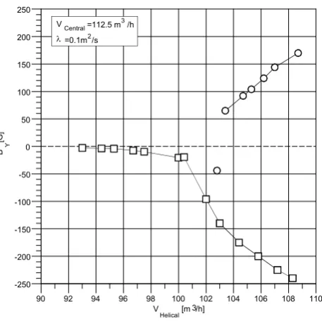
state, here the pure hydrodynamic state. There are on the one side the continuously emerging dynamo states indicated by the slowly increasingB-field for lower helical flow rates and drastically increasing values beyond a certain threshold flow rate. On the other side we find also saturated dynamo states which have a magnetic field of opposite direction. They exist only above a certain value of the flow rate. These states can not be obtained experimentally by increasing the flow rates in a quasi-steady way from subcritical to supercritical con-ditions. They represent the stable part of the isolated branch of an imperfect bifurcation graph. In our experiment these magnetic states were enforced by imposing suddenly for a short period of time an external magnetic field of opposite direction to a dynamo state on the continuous branch. The external magnetic field was generated by two properly ar-ranged Helmholtz-coils close to the test module. Depending on the intensity of the externalB-field a transition could be realized from states on the continuous branch to states on the isolated one. Furthermore, we find that the dynamo mag-netic field changes direction in a transient, if the helical flow rates are reduced below a certain threshold value, thus indi-cating the existence of a the turning point in the bifurcation diagram. The observations show that after the transient the previous states on the continuous branch is not exactly recov-ered, rather a magnetic field of lower intensity is found. This phenomenon has to be investigated in more detail furtheron.
90 92 94 96 98 100 102 104 106 108 110 -250
-200 -150 -100 -50 0 50 100 150 200 250
V Helical [m 3/h]
B Y
[G
]
VCentral =112.5 m3/h
l=0.1m2/s
Fig. 5. A typical bifurcation diagram of the Karlsruhe dynamo. Here, the measured magnetic field intensity iny−direction (BY) at
x = y = z = 0 is shown as a function of the helical flow rate (VHelical) and for a fixed central flow rate (VCentral).
4 Summary
It has been demonstrated experimentally that a permanent dynamo can be generated in a finite quasi-homogeneous do-main of a well conducting fluid by a proper arrangement of spiral vortices within. The onset of self-exitation is char-acterized by a drastic increase of the pressure losses in the flow channels of the test module due to the effect of increas-ing Lorentz forces. As predicted by theory the mode of the observed magnetic field is non-axisymmetic. Two different magnetic states of opposite field direction were realized in the experiments, one by increasing the volumetric flow rates in a quasi-steady process, the other by an external magnetic pulse of opposite direction and adequate intensity.
References
Apel, A., Apstein, E., R¨adler, K.-H., and Reinhardt, M.: Contribu-tion to the theory of the planned Karlsruhe dynamo experiment, AIP-Report, 96, 1996.
Braginsky, S., Roberts, P. H.: Equations governing convection in the Earth’s core and the geodynamo, Geophys. Astrophys. Fluid Dyn., 79, 1–97, 1995.
Busse, F. H.: Magnetohydrodynamics of the Earth’s Dynamo, An-nual Rev. Fluid Mech., 10, 435–462, 1978.
Busse, F. H. and Carrigan, C. R.: Laboratory Simulation of Thermal Convection in Rotating Planets and Stars, Science, 191, 81–83, 1976.
170 U. M¨uller and R. Stieglitz: The Karlsruhe Dynamo Experiment
Busse, F. H., M¨uller, U., Stieglitz, R., and Tilgner, A.: A two-scale homogeneous dynamo, an extended analytical model and an ex-perimental demonstration under development, Magnetohydrody-namics, 32, 235–248, 1996.
Roberts, G. O.: Spatially periodic dynamos, Phil. Trans. R. Soc., London, A, 266, 535–558, 1970.
Roberts, G. O.: Dynamo action of fluid motions with two-dimensional periodicity, Phil. Trans. R. Soc., London, A, 271, 411–454, 1972.
Stieglitz, R. and M¨uller, U.: Geodynamo – Eine Versuchsanlage
zum Nachweis des homogenen Dynamoeffektes, FZKA Report FZKA-5716, 1996.
Stieglitz, R. and M¨uller, U.: Experimental demonstration of a ho-mogeneous dynamo, Physics of Fluids, 13, 561–564, 2001. Tilgner, A.: A kinematic dynamo with a small scale velocity field,
Physics Letters A, 226, 75–79, 1997.