DOI: 10.1051/epjconf/20135702004 C
Owned by the authors, published by EDP Sciences, 2013
Advanced cold molecule electron EDM
Wesley C. Campbell
2, Cheong Chan
1, David DeMille
1, John M. Doyle
3,a,
Gerald Gabrielse
3, Yulia V. Gurevich
1, Paul W. Hess
3, Nicholas R. Hutzler
3,
Emil Kirilov
4, Brendon O’Leary
1, Elizabeth S. Petrik
3, Ben Spaun
3and Amar C. Vutha
51Yale University Department of Physics, New Haven, CT, USA
2University of California Department of Physics and Astronomy, Los Angeles, CA, USA 3Harvard University Department of Physics, Cambridge, MA, USA
4Universität Innsbruck Institut für Experimentalphysik, Innsbruck, Austria 5York University Department of Physics and Astronomy, Toronto, ON, Canada
Abstract. Measurement of a non-zero electric dipole moment (EDM) of the electron within a few orders
of magnitude of the current best limit of|de|<1.05×10⁻²⁷e·cm [1] would be an indication of physics beyond the Standard Model. The ACME Collaboration is searching for an electron EDM by performing a precision measurement of electron spin precession in the metastableH 3
1state of thorium monoxide
(ThO) using a slow, cryogenic beam. We discuss the current status of the experiment. Based on a data set acquired from 14 hours of running time over a period of 2 days, we have achieved a 1-sigma statistical uncertainty ofde=1×10⁻²⁸e·cm/
√
T, whereT is the running time in days.
1. INTRODUCTION
At accelerators such as the Large Hadron Collider (LHC), particles of the highest accessible energies are used to probe physics at its most fundamental level. On a complementary front, the precise measurement techniques of atomic physics can access the vacuum fluctuations these massive particles produce. Because the search for the electron electric dipole moment (EDM) is a sensitive probe of new physics, this effort has long been at the forefront of such research [2,3]. A high-precision measurement that discovers the electron EDM or sets a stringent new limit upon its size would place strong constraints on extensions to the Standard Model of particle physics (SM). A general feature of SM extensions is the prediction of an EDM for electrons and nucleons, with many theories indicating an electron EDM just below the current upper limit [4,5] (de<1.05×10⁻²⁷e·cm with 90% confidence [1],
measured by the Hinds group). The symmetries of the SM, on the other hand, strongly suppress EDMs, giving rise to electron EDM predictions over a hundred billion times smaller than the current limit [6]. One well motivated SM extension is supersymmetry. Supersymmetric models require fine tuning of supersymmetric parameters to fit the current EDM limits [7,8]. An electron EDM measurement that is 10–100 times as sensitive as the current upper bound must either observe an EDM, revealing a breakdown of the Standard Model, or set a new limit requiring such unnatural suppression of supersymmetric parameters that many supersymmetric models would have to be revised or rejected [9]. The Advanced Cold Molecule EDM Experiment (ACME) [10] is a new effort to measure the electron EDM using thorium monoxide (ThO). ThO is a polar molecule with two valence electrons. In the H3
1
ae-mail:
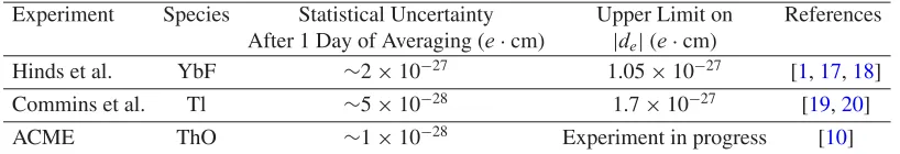
Table 1. Comparison of the statistical sensitivity of ACME with that of the two experiments placing the strongest
limits on the electron EDM. The estimated statistical uncertainty for the Tl and YbF experiments assumes a duty cycle of 100%.
Experiment Species Statistical Uncertainty Upper Limit on References After 1 Day of Averaging (e·cm) |de|(e·cm)
Hinds et al. YbF ∼2×10⁻²⁷ 1.05×10⁻²⁷ [1,17,18]
Commins et al. Tl ∼5×10⁻²⁸ 1.7×10⁻²⁷ [19,20]
ACME ThO ∼1×10⁻²⁸ Experiment in progress [10]
state [11], one of these electrons occupies a-orbital, and its EDM is relativistically enhanced due to the Sandars effect [12], while the other valence electron occupies a-orbital and allows the molecule to be easily polarized. The-state electron interacts with approximately 20 full atomic units of effective electric field (∼100 GV/cm) in a molecular state that can be oriented with very modest laboratory fields (∼10 V/cm) [13]. The interaction of this effective molecular field with a non-zero electron EDM would manifest itself as a phase shift in ACME’s Ramsey-type measurement protocol. Taking advantage of recent improvements in technologies and methods, including a new slow, cold, and intense beam source [14] and ThO’s near-ideal 3
1 state structure (see e.g. [10, 15,16]), we have developed an experiment with the unprecedented electron EDM statistical sensitivity of about 1×10⁻²⁸ e·cm in one day of averaging time. This is 10 times better than the current experimental limit [1]. As discussed below, ACME’s systematic errors are also projected to be smaller than those of past experiments and can be checked with high precision on the time scale of days. We are currently studying various possible sources of systematic error in preparation for reporting a new result.
2. ATOMIC AND MOLECULAR ELECTRON EDM EXPERIMENTS
The signature of a permanent electron EDM,de, is an energy shiftEDM of an unpaired electron (or electrons) in an electric fieldE:
EDM = −de·E. (1)
In the vicinity of some atomic nuclei, electrons experience very strong electric fields [12,21,22]. These internal atomic and molecular fields can be partially or completely oriented by polarizing the atom or molecule, which together with relativistic effects gives the electron EDM a non-zero average energy shift. Per Eq. (1), this shift can be interpreted as an interaction between de and an average effective
electric fieldEeffproduced by the atomic nucleus. The size ofEeffcan be shown to scale approximately as the cube of the atomic numberZ [23]. Thus, the species that yield the most sensitive (i.e. largest
EDM) electron EDM measurements are heavy (largeZ), highly polarizable atoms and molecules with unpaired valence electrons whose wavefunctions have a large amplitude near the nucleus.
These principles have guided the search for electron EDM for the last fifty years, during which time the strongest limits have consistently been set by atomic and molecular experiments. Table1summarizes the two most recent EDM upper bounds, obtained with atomic thallium (Tl) and the polar molecule ytterbium fluoride (YbF), and compares the sensitivity of these experiments with ACME’s demonstrated sensitivity.
2.1 Thorium monoxide electron EDM
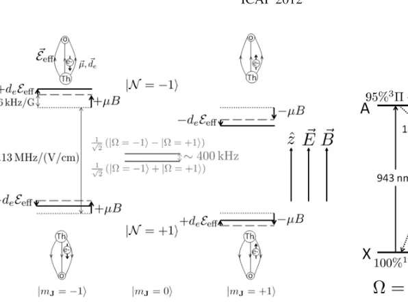
Figure 1. Sublevel structure of theH3
1state of ThO. In the absence
of applied Ezˆand Bˆzfields, the stationary states are the-doubled parity eigenstates √1
2(|= +1 ± |= −1), which are split by a few
hundred kHz (solid gray lines). E-fields of∼10 V/cm fully mix these doublets in the MJ≡zˆ·J= ±1 states by resolving the aligned and anti-aligned orientations (N≡sgn( ˆn·E)=sgn(ˆz·E)MJ= ±1) of the internuclear axis ˆn. The linear Stark splitting between theseNstates (dotted gray lines) is measured to be 2.13 MHz/(V/cm). In an applied
B-field, the measured Zeeman shift (dashed gray lines) between the MJ= ±1 states of each N sublevel is ±12 kHz/G [13]. Ifde=0, theseMJlevels experience an additional relative shift equal to±2deEeff (solid black lines). These relative shifts are in opposite directions in the twoN levels sinceEeffpoints in opposite directions. The ACME
experiment is performed by measuring the energy shift between the states|N,MJ= −1and|N,MJ = +1for bothN as a function of the electric and magnetic field and looking for a shift that depends only on the signs ofN and E. See Sects.3.1and4.
Figure 2. Key levels and
trans-itions in ThO, based on [10,32,33]. All relevant states are in the ground vibrational level. The electronic states are denoted by letters, and the angular momentum character of each state is indicated by molecular spectroscopy symbols. The wavelength of each transition is given in nm. The ACME measurement scheme makes use of both diode laser pumped excitations (solid arrows), and spontaneous decays (dotted arrows), as described in Sect.3.1.
Meyer and Bohn [11] have calculated the effective internal electric fieldEeffof fully polarized ThO to be∼100 GV/cm, which is among the largest of any investigated species. This field is nearly 4 times as large as the estimated field in fully polarized YbF [24], nearly 8 times as large as theEeffachieved in partially polarized YbF in the Hinds experiment [17], and over 1000 times larger than theEeffachieved in the Tl experiment [19]. Moreover, ThO possesses a low-lying metastable stateH31 (see Fig.1), which exhibits several features beneficial to an EDM experiment. Firstly, it has a measured lifetime of 1.8 ms [10], sufficient to perform our Ramsey experiment in a molecular beam with a coherence time of 1.2 ms (see Sect.3.1). This is comparable to the coherence times in both the YbF (642s [1]) and the Tl (∼2.5 ms [25]) electron EDM experiments. Secondly, the spin and orbital magnetic moments of a state with3
1 angular momentum cancel almost perfectly [10], and the residual g-factor is measured to be gH,J=1=4.3(3)×10−3 [13]1. This small magnetic moment renders the experiment highly insensitive to magnetic field imperfections.
1To avoid confusion with similar definitions of the molecular g-factor, we specify that in the present paper’s notation, the energy
Finally, the most advantageous property of theH3
1 state of ThO is its extremely large static electric dipole polarizability resulting from a pair of nearly degenerate, opposite-parity sublevels split by only a few hundred kHz [11, 15, 26]. This level structure gives polarizabilities on the order of 104 or more times larger than for a more typical diatomic molecule state, in which an applied electric field polarizes the molecule by mixing opposite-parity rotational levels typically spaced by many GHz. The opposite-parity sublevelsH,J =1 state are formed by even and odd combinations of molecular orbitals with opposite signs of the quantum number ≡nˆ·J (the projection of the total angular momentum on the molecular bond axis) and are a general feature of states with≥1 in Hund’s case (c) molecules [27,28]. Such “-doubled” states are immensely valuable to electron EDM searches because they can be fully mixed in electric fields of only a few tens or hundreds of V/cm, completely polarizing the molecule [28,29]. Thus, EDM experiments on molecules with-doublets can take full advantage of the molecules’ effective internal field while avoiding the technical challenges and potential systematic errors introduced by large lab fields. Furthermore, because the effective electric field in a fully polarized molecule is independent of the externally applied electric field E, the electron EDM signal is also independent of the magnitude of the applied field [see Eq. (6)], allowing such experiments to set limits on systematic effects correlated with|E|. Another benefit of the-doublet in ThO is that the polarizedH-state molecule can be spectroscopically prepared with its dipole either aligned or anti-aligned with E, allowing us to switch the sign of the electric field experienced by the electron EDM without physically changing the laboratory field [30]. As discussed in Sect.4.2, this provides a way to rule out systematic errors correlated with the sign of the applied field, such as leakage currents, motional magnetic fields, and geometric phases [10,31]. The ACME experiment is currently taking data to improve its statistics and set limits on possible systematic errors.
Besides these features, ThO also provides manifold technical advantages. All of the relevant optical transitions (see Fig.2) are well studied [26,34–38] and accessible to diode lasers. In addition, ThO has no nuclear spin and so avoids the complexities of hyperfine structure. Finally, despite the fact that ThO is chemically reactive and its precursors are highly refractory, it can be produced in large quantities in a cryogenic buffer gas beam [14] (see Sect.3.2).
3. ACME EXPERIMENT OVERVIEW
In order to measure the electron EDM, ACME produces a high-flux beam of ThO and uses an optical state preparation and readout scheme to detect the Ramsey fringe phase shift resulting from a non-zero de·Eeff. The measurement and apparatus are described here.
3.1 Measurement scheme
The ACME apparatus and measurement scheme are illustrated in Fig.3and described in [10]. Molecules from the beam source enter the interaction region and are intercepted by an optical pumping laser tuned to theX→Atransition (see Fig.2). Excitation by this laser and subsequentAHspontaneous decay populate theH state. The measurement is performed in select sublevels in the ground ro-vibrational level (v=0,J =1) of the H state. In the absence of an applied electric field E, sublevels in this manifold are identified by their quantum numbers MJ = ±1, 0 (projection of J along the lab-frame
quantization axis ˆz), andP = ±1 (parity). The opposite-parity-doublet levels in the H state have a very small splitting (∼400 kHz [11, 13,26]), which we neglect. When a sufficiently large (more than∼10 V/cm) electric field E is applied collinear with ˆz, theP = ±1 sublevels with the same value of MJ mix completely; the resulting eigenstates have complete electrical polarization, described by
the quantum numberN ≡sgn ( ˆn·E)= ±1. (TheMJ =0 sublevels do not mix.) The relevant energy
levels are shown in Fig.1. The tensor Stark shiftSt is defined as the magnitude of the shift of the oriented |MJ| =1 levels from the unperturbed MJ =0 levels. A magnetic field B≈10 mG is also
Figure 3. Schematic of the ACME apparatus and measurement described in Sect.3. On the left, a pulse of gas-phase ThO molecules is produced and cooled in a buffer gas cell and flows out towards the right in a beam (see Sect.3.2). This beam enters a magnetically shielded interaction region where uniform, parallel E- and B-fields are applied. At the entrance of the field region, the molecules are pumped from the|X,v=0,J =1,MJ = ±1states to the|A,v=0,J=0,MJ=0state, where they spontaneously decay to the|H,v=0,J =1state, equally populating the|J =1,M= ±1,N= ±1sublevels (see Fig.1). Next, a pure superposition of Zeeman sublevels
|XN [see Eq. (9)] is prepared in one of the two N states of H by pumping out the orthogonal superposition
|YNusing linearly polarized light resonant with the|H,v=0,J =1,N= ±1 → |C,v=0,J=1,MJ =0 transition. Next, the molecule state precesses in the applied E and B fields for approximately 1.1 ms as the beam traverses the 22-cm-long interaction region. The relative phase accumulated between the Zeeman sublevels depends ondethrough Eq. (6). Near the exit of the field region, we read out the final state of the molecules: By exciting the |H,v=0,J =1,N = ±1 → |C,v=0,J =1,MJ=0transition with rapidly switched orthogonal ( ˆx and ˆy) linear polarizations and detecting theCXfluorescence from each polarization, we project the population onto the|XNand|YNstates. The phase from Eq. (6) is given by cos 2=A[see Eq. (11)].
Since the H state is populated by spontaneous decay fromA, it is initially in a mixed state, with all sublevels used in the experiment approximately equally populated. By coupling the molecules to a strong state-preparation laser driving theH →C transition, we deplete the coherent superposition of|MJ = ±1;Nthat couples to the laser polarization ˆp, leaving behind a dark state. With the laser
polarization ˆp=yˆfor example, the prepared state of the molecules is
|N
i =
1
√
2(|MJ = +1;N + |MJ = −1;N) (2) withN = +1 (N = −1) corresponding to the lower (upper)-doublet component. The tensor Stark shiftSt is large enough that levels with different values of N are spectrally resolved by the state preparation laser. Hence a particular value ofN is chosen by appropriate tuning of the laser frequency.
The energy shifts of theMJ = ±1 levels in Fig.1are given approximately by
(MJ,N, E, B)=gH,J=1MJBBBˆ −dH,J=1NE+deEeffMJNEˆ, (3)
wheregH,J=1=4.3(3)×10−3anddH,J=1=0.84(2)ea0are the magnetic g-factor and electric dipole moments of theH,J =1 state respectively [13],Bis the Bohr magneton,eis the electron charge, and
a0is the Bohr radius. The terms (from left to right) give the interaction of the magnetic dipole with the external magnetic field, the Stark shiftSt, and the interaction of the electron EDM with the effective molecular field. Here we assume that theH-state is fully polarized, which occurs in external fields of
∼10 V/cm, much smaller than the typical experimental field of 140 V/cm. The magnitudes of applied field vectors are given in Roman font, e.g.B= |B|. The hat denotes the sign of a quantity’s projection on the lab-fixed quantization axis of the experiment, e.g. ˆB=sgn(ˆz·B). This simple formula neglects a large number of important terms, such as the electric field dependence of the g-factors [39], background fields, motional fields, etc., but this expression will be sufficient to explain the basic measurement procedure.
After free evolution during flight (over a distance L=22 cm in our experiment), the final wavefunction of the molecules is
|N
f =
1
√
2
ei|MJ = +1;N +e−i|MJ = −1;N
. (4)
For a molecule with velocityvalong the beam axis, the accumulated phasecan be expressed as
=
x=L
x=0
[(MJ = +1,N, E, B)−(MJ = −1,N, E, B)] dx
2v (5)
= x=L
x=0
deEeffNEˆ +gH,J=1BBBˆ
dx
v ≡E+B. (6)
Using the fact that our beam source has a narrow forward velocity distribution (with average forward velocityvand spreadvv, see Sect.3.2), we make the approximation that all molecules experience the same phase shift as they traverse the interaction region. Furthermore, because the E- and B-fields are highly uniform along the length of the interaction region, we can pull out the integrand and write:
E ≈deEeffNEˆ L
v, and (7)
B≈gH,J=1BBBˆ L
v (8)
for all molecules in the beam.
The phaseis detected by measuring populations in two “quadrature components”|XNand|YN of the final state, where we define
|XN ≡ √1
2(|MJ = +1;N + |MJ = −1;N) , and
|YN ≡ √1
2(|MJ = +1;N − |MJ = −1; N) . (9) The quadrature state|XN(|YN) is independently detected by excitation with a laser coupling theHand
Cstates whose polarization is ˆd =xˆ(ˆd =yˆ). TheCstate quickly decays to the ground state, emitting
fluorescence at 690 nm, which we collect with an array of lenses and focus into fiber bundles and light pipes. These in turn deliver the light to two photomultiplier tubes (PMT’s),2where it is detected.
This scheme allows for efficient rejection of scattered light from the detection laser since the emitted fluorescence photons are at a much shorter wavelength than the laser.
The probability of detecting a molecule in the quadrature state |XN (|YN), given by PX=
| XN|Nf |2 (P
Y = | YN|Nf |2), can be expressed as PX=cos2 (PY =sin2). The detected
fluorescence signal from each quadrature state is proportional to its population. We express these signals (SXandSY) as a number of photoelectron counts per beam pulse, and writeSX(Y)=S0PX(Y), whereS0 is the total signal from one beam pulse. Thus,SXandSY trace out two sinusoidal curves (or Ramsey
fringes) of opposite phase as a function of applied magnetic field. For the highest sensitivity to de,
we “sit on the side of the Ramsey fringe” where small changes inE are most noticeable, i.e. where
*/*E[SX(Y)] is maximized. Therefore, we adjust the magnetic field to yield a bias phase|B| =/4 and rewriteSXandSY as
SX≈S0
−BˆE+1 2
, andSY ≈S0
+BˆE+1 2
· (10)
Then the EDM phaseEcan be determined by constructing the quantityA, known as the asymmetry:
A≡ SY−SX SX+SY
≈2 ˆBE (11)
ˆ
B
2A≈E. (12)
Note from Eq. (7) thatEis odd in E andN, even in B, and proportional toEeff. In Sect.4we discuss how to use these correlations to isolate the EDM term from various systematic effects.
The shot-noise limited statistical uncertainty in E is 1/(2C√N), where N is the total number of photon counts and the quantity C introduced in this expressions is the Ramsey fringe contrast (or visibility), which accounts for inefficiencies in state preparation and varying precession times for different molecules. Therefore, the shot-noise limited uncertainty in the measured EDM value is [from differentiatingdewith respect toEin Eq. (7)] [10]
de=
2CEeff( ˙N T)1/2
, (13)
where=L/vis the precession time of the molecules in the fields, ˙Nis the time-averaged counting rate of the detectors, andT is the total experimental running time. The quantitiesandEeffare determined by physical properties of theH-state, as described above, and the large ThO fluxes achieved by the ACME beam source help to keep our uncertainty low by providing large ˙N.
3.2 ThO buffer gas beam
Both the 4 K and the 50 K chambers have a window to admit the ablation laser and apertures to transmit and collimate the buffer gas beam.
The source of ThO molecules is a ceramic target of thoria (ThO2) made in-house using established techniques [10,44]. ThO molecules are introduced into the cell via laser ablation: A Litron Nano TRL 80-200 pulsed Nd:YAG laser is fired at the ThO2 target, creating an initially hot plume of gas-phase ThO molecules. The ablation pulse energy is set to 75–100 mJ and the repetition rate to 50 Hz. On a time scale rapid compared to the emptying time of the cell into the beam region, the hot ThO molecules thermalize with the 16 K buffer gas in the cell. Continuous neon flow at∼40 SCCM (standard cubic centimeters per minute) maintains a buffer gas density of n0≈1015–1016cm−3 (≈10−3–10−2 Torr, where the subscript “0” indicates the steady-state value of the quantity in the cell). This is sufficient for rapid translational and rotational thermalization of the molecules and for producing hydrodynamic flow out of the cell aperture that entrains a significant fraction of the molecules before they can diffuse to the cell walls and stick. The result is a 1–3 ms long pulsed beam of cold ThO molecules embedded in a continuous flow of buffer gas.
Just outside the cell exit, the buffer gas density is still high enough for ThO–Ne collisions to play a significant role in the beam dynamics. The average thermal velocity of the buffer gas atoms is higher than that of the molecules by a factor of√mmol/mb, where the subscripts “b” and “mol” indicate buffer gas and molecule quantities, respectively. Consequently, the ThO molecules (mmol=248 amu) experience collisions primarily from behind, with the fast neon atoms (mb=20 amu) pushing the slower ThO molecules ahead of them as they exit the cell. This accelerates the molecules to an average forward velocity vf that is larger than the thermal velocity of ThO. As the buffer gas pressure in the cell is
increased,vfapproachesv0,b, the thermal velocity of the buffer gas.
The angular distribution of a beam has a characteristic apex angle given by tan( /2)≡v⊥/2vf,
wherev⊥is the transverse velocity spread of the beam. For the ACME beam, the apex angle is ≈30◦, and the characteristic solid angle is ≈0.3 sr. The beam velocity is measured to be∼180 m/s. As the gas cloud expands nearly isentropically out of the cell into the vacuum, it must also cool. The measured final longitudinal and rotational temperature of the beam is∼4 K, yielding a forward velocity distributionvof∼30 m/s FWHM (full width at half maximum) and efficiently populating low-lying rotational levels in the ground electronic state (e.g.∼30% inJ =1). The total number of molecules per pulse in the few most populated quantum states is measured to be ∼1011. This slow, cold, high-intensity molecular beam provides ACME with a long interaction time over a short distance, low phase decoherence due to the narrow velocity spread, and a high count rate ˙N.
4. DATA ANALYSIS
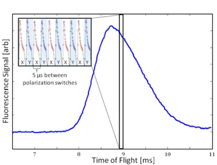
Figure 4 shows some example data collected using the scheme described in Sect. 3. As derived in Sect.3.1, this measurement scheme determines the accumulated phase due to the energy shift between the twoMJ levels in eitherN state. This energy shift is given by [see Eq. (3)]:
(N, E, B)≡(MJ = +1,N, E, B)−(MJ = −1,N, E, B) (14)
=2gH,J=1BBBˆ +2deEeffNEˆ. (15) If we wish to measure de in a way that is insensitive to noise or uncertainty in the external magnetic
Figure 4. Average fluorescence signal from a molecule pulse vs. time since ablation. Each pulse of molecules is ∼2 ms wide. The inset shows a zoom-in on the fluorescence signal over a 50s interval, revealing the 100 kHz chopping of the probe laser polarization between ˆd =xˆand ˆd=yˆ, used to measureSXandSY, respectively.
separate the spin and EDM precession by reversing N or E since the two terms also have opposite parity under reversal of those quantities.
In a real experiment a number of uncontrolled effects are present, including background fields, correlated fields (e.g. magnetic fields from leakage currents which reverse synchronously with E), motional fields, geometric phases, and many more [2]. Despite the best experimental efforts, these effects may cause energy shifts larger than the electron EDM; however, we can isolate the electron EDM from these effects using its unique “NEB= − − +” parity, i.e. odd parity under molecular dipole or electric field reversal and even parity under magnetic field reversal.
If we perform 8 repeated experiments, with each of the 23=8 combinations of±N,±E,±B, we can take sums and differences to compute the 8 different possible parities underN, E, B reversals, as shown in Table3. Apart from higher-order terms, such as cross-terms between background electric and magnetic fields, the electron EDM is the only term withNEB= − − +parity. This technique of isolation by parity is how EDM experiments can perform sensitive measurements of the electron EDM with achievable levels of control of experimental parameters. We also perform a number of auxiliary switches to check for other systematic dependences of theNEB= − − +signal, such as rotating the polarization angle of the pump and probe lasers and interchanging the positive and negative field plate voltage leads.
4.1 Statistical sensitivity
The shot-noise limited sensitivity of the ACME experiment is given by Eq. (13). Other sources of technical noise may cause the achieved experimental sensitivity to be larger, but our measurements indicate that we are very near the shot noise limit [45].
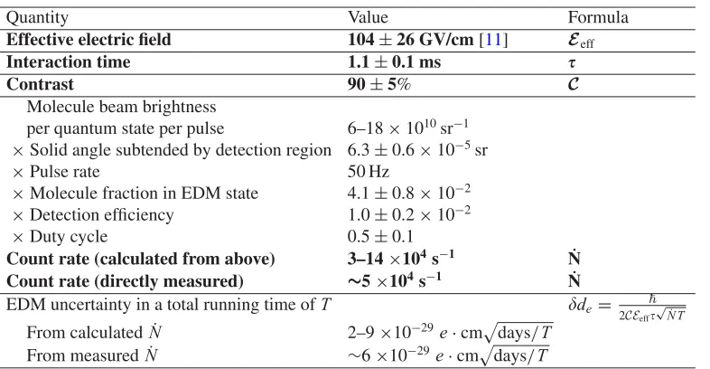
Table2derives ACME’s expected shot-noise limited statistical EDM sensitivity from measured and calculated quantities. In this table, the interaction timeis equal to the length of the interaction region
L=22 cm divided by the measured beam velocityv=180 m/s [14]. The contrastCis determined by measuring the slope of the Ramsey fringe at|B| =/4.
The count rate can be determined directly, by converting the PMT signal to a photon number, or indirectly, by starting with the measured molecule beam intensity and multiplying by the efficiency of each step in the measurement scheme. The molecule beam brightness in a singleMJ sublevel of
Table 2. Shot-noise limited electron EDM uncertainty estimated from measured and calculated quantities. The
measured uncertainty is about 1.4 times the shot noise limit. Quantities in bold are ingredients in Eq. (13). All quantities other than the effective electric fieldEeffare either experimental inputs or are derived from measurements taken in the ACME experiment’s ordinary running configuration as described in the text.
Quantity Value Formula
Effective electric field 104±26 GV/cm [11] Eeff
Interaction time 1.1±0.1 ms
Contrast 90±5% C
Molecule beam brightness
per quantum state per pulse 6–18×1010sr−1
×Solid angle subtended by detection region 6.3±0.6×10⁻⁵sr
×Pulse rate 50 Hz
×Molecule fraction in EDM state 4.1±0.8×10⁻² ×Detection efficiency 1.0±0.2×10⁻²
×Duty cycle 0.5±0.1
Count rate (calculated from above) 3–14×104s−1 N˙
Count rate (directly measured) ∼5×10⁴s−1 N˙
EDM uncertainty in a total running time ofT de=
2CEeff
√
˙
N T
From calculated ˙N 2–9×10⁻²⁹e·cmdays/T From measured ˙N ∼6×10⁻²⁹e·cmdays/T
beam source, sodetect=(1 cm)2/(126 cm)2. The pulse rate of the YAG is set to 50 Hz. The fraction of molecules available for detection is given by:
Mol. fraction in EDM state=(optical pumping efficiency of X→AH)
×(fraction of H state sublevels used)×exp[−/(H state lifetime)]
×(Beam attenuation due to background collisions) (16)
=0.67×1/6×exp(−1.2 ms/1.8 ms)×0.8=0.04, (17) where each value in Eq. (16) was measured separately. The fluorescence detection efficiency is the product of the measured geometric collection efficiency of the detection optics (∼14%) and the quantum efficiency of the PMT’s (10%). The duty cycle is the fraction of the time during the run that data is being collected. ACME’s duty cycle is presently around 50% because of the time required to switch various parameters (e.g. laser polarization angle), degauss the magnetic shields, optimize the ablation yield, and tune up the lasers during the run.
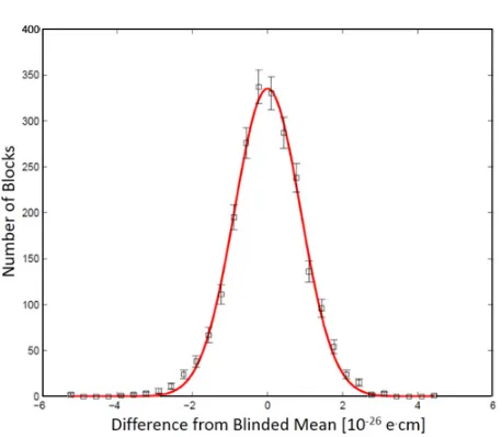
Figure5 shows a set of EDM data (with an unknown blind offset added during data processing) taken over a total of 14 hours on 2 different days. The 1-sigma statistical uncertainty in the EDM from this plot is 1.6×10⁻²⁸e·cm in 14 hours. This corresponds to a 1-sigma statistical error bar of about 1×10⁻²⁸e·cm in one day of averaging time, which is consistent within uncertainty with 1.4 times the shot-noise limit estimated in Table2.
4.2 Systematic checks
Figure 5. Distribution of blinded values of the electron EDM calculated from data taken over a total of 14 hours on
2 separate days. Each of the 2300 measurements plotted on the histogram was calculated from one “block” of data, where each block consists of 800 molecular beam pulses with various parameter switches. The error bars show the standard deviation on the number of blocks in each histogram bin. The solid line is a fitted Gaussian distribution with a standard deviation of 8.5×10⁻²⁷e·cm. The 1-sigma statistical uncertainty in the EDM from this plot is
1.6×10⁻²⁸e·cm in 14 hours, which corresponds to a 1-sigma statistical error bar of about 1×10⁻²⁸e·cm in one
day of averaging time.
Table 3. Parity of energy shifts of selected effects in the ACME measurement. The difference between the g-factors
of the twoN-states ofH isg[39], and the subscript nr denotes the non-reversing component of an applied field. Products of terms denote correlations between those terms. The terms with+ − −parity are higher-order and negligibly small.
NEB Parity Quantities
+ + + Electron spin precession in background (non-reversing) magnetic fieldBnr, Pump/probe relative polarization offset
+ + − Electron spin precession in applied magnetic field
+ − + Leakage currentsBleak − + + gBnr,gBleakEnr
+ − − —
− + − Electric-field-dependent g-factors [39]
− − + Electron EDM
− − − gEnr
quantityX(for example, a non-reversing electric or magnetic field) mimics the electron EDM according to the relation de,false(X)=X. If the quantity X can only be determined or controlled to the level Xcontrol, then our measurement will have a systematic uncertainty due to imperfections in X of orderde,X≈ |Xcontrol|. The quantity Xcontrol can typically be determined with direct measurements (magnetometers to measure magnetic fields, spectroscopic techniques to measure electric fields, optical cavities to determine laser noise, etc.), but it remains to determine. The general technique to determine
currently in the process of varying a large number of experimental parameters to look for unexpected systematic effects.
5. CONCLUSION
The discovery of an electron EDM or an improvement on its upper limit by an order of magnitude or more would have a significant impact on our understanding of fundamental particle physics. We have described an ongoing experiment to search for the electron EDM using cold ThO molecules. This experiment has achieved a one-sigma statistical uncertainty of 1×10⁻²⁸e·cm/√T, where T is the running time in days. This advance over previously published electron EDM experiments was made possible by the combination of a greatly increased molecular flux provided by our new cold molecular beam source and our choice of the ThO molecule, which is fully polarizable in small fields and has the highest effective electric field of any investigated species. We are now working to put limits on systematic errors that may be present in the experiment. ThO, due to its advantageous level structure, is particularly well suited to the suppression and rejection of systematic effects while searching for the electron EDM.
References
[1] J. J. Hudson, D. M. Kara, I. J. Smallman, B. E. Sauer, M. R. Tarbutt, and E. A. Hinds, Nature 473, (2011) 493–496.
[2] I. B. Khriplovich and S. K. Lamoreaux, CP Violation Without Strangeness: Electric Dipole Moments of Particles, Atoms, and Molecules (Springer-Verlag, Berlin 1997).
[3] W. Bernreuther and M. Suzuki, Reviews of Modern Physics 63, (1991) 313–340.
[4] E. D. Commins and D. P. DeMille, “The Electric Dipole Moment of the Electron.” In B. L. Roberts and W. J. Marciano, Editors, Lepton Dipole Moments (World Scientific, Singapore 2009) 519–581.
[5] N. Fortson, P. Sandars, and S. Barr, Physics Today 56, (2003) 33–39.
[6] M. E. Pospelov and I. B. Khriplovich, Soviet Journal of Nuclear Physics 53, (1991) 638–640. [7] S. Abel, S. Khalil, and O. Lebedev, Nuclear Physics B 606, (2001) 151–182.
[8] Y. Nir, ArXiv (1999) 9911321v2.
[9] M. Pospelov and A. Ritz, Annals of Physics 318, (2005) 119–169.
[10] A. C. Vutha, W. C. Campbell, Y. V. Gurevich, N. R. Hutzler, M. Parsons, D. Patterson, E. Petrik, B. Spaun, J. M. Doyle, G. Gabrielse, and D. DeMille, Journal of Physics B 43, (2010) 074007. [11] E. L. Meyer and J. L. Bohn, Physical Review A 78, (2008) 01052(R).
[12] E. D. Commins, J. D. Jackson, and D. P. DeMille, American Journal of Physics 75, (2007) 532–536.
[13] A. C. Vutha, B. Spaun, Y. V. Gurevich, N. R. Hutzler, E. Kirilov, J. M. Doyle, G. Gabrielse, and D. DeMille, Physical Review A 84, (2011) 034502.
[14] N. R. Hutzler, M. F. Parsons, Y. V. Gurevich, P. W. Hess, E. Petrik, B. Spaun, A. Vutha, D. DeMille, G. Gabrielse, and J. M. Doyle, Physical Chemistry Chemical Physics 13, (2011) 18976–18985.
[15] E. R. Meyer, J. L. Bohn, and M. P. Deskevich, Physical Review A 73, (2006) 062108. [16] A. C. Vutha, Ph.D. Thesis, Yale University (2011).
[17] B. E. Sauer, J. J. Hudson, D. M. Kara, I. J. Smallman, M. R. Tarbutt, and E. A. Hinds, Physics Procedia 17, (2011) 175–180.
[18] D. M. Kara, I. J. Smallman, J. J. Hudson, B. E. Sauer, M. R. Tarbutt, and E. A. Hinds, New Journal of Physics 14, (2012) 103051.
[20] E. D. Commins, S. B. Ross, D. DeMille, and B. C. Regan, Physical Review A 50, (1994) 2960–2977.
[21] E. E. Salpeter, Physical Review 112, (1958) 1642–1648. [22] P. G. H. Sandars, Physics Letters 14, (1965) 194–196.
[23] D. Budker, D. F. Kimball, and D. P. DeMille, Atomic Physics: An Exploration Through Problems and Solutions (Oxford University Press, Inc., New York 2004).
[24] M. S. Mosyagin, M. G. Kozlov, and A. V. Titov, Journal of Physics B 31, (1998) L763–L767. [25] B. C. Regan, Ph.D. Thesis, Berkeley (2001).
[26] G. Edvinsson and A. Lagerqvist, Physica Scripta 30, (1984) 309–320.
[27] G. Herzberg, The Spectra and Structures of Simple Free Radicals (Cornell University Press, Ithaca 1971).
[28] D. DeMille, F. Bay, S. Bickman, D. Kawall, D. Krause, Jr., S. E. Maxwell, and L. R. Hunter, Physical Review A 61, (2000) 052507.
[29] D. DeMille, F. Bay, S. Bickman, D. Kawall, L. R. Hunter, D. Krause, Jr., S. Maxwell, and K. Ulmer, American Institute of Physics Conference Proceedings 596, (2001) 72–83.
[30] D. Kawall, F. Bay, S. Bickman, Y. Jiang, and D. DeMille, AIP Conference Proceedings 698, (2004) 192–195.
[31] A. Vutha and D. DeMille, ArXiv, (2009) 0907.5116v1.
[32] G. Edvinsson and A. Lagerqvist, Journal of Molecular Spectroscopy 113, (1985) 93–104. [33] J. Paulovi˘c, T. Nakajima, K. Hirao, R. Lindh, and P. A. Malmqvist, Journal of Chemical Physics
119, (2003) 798–805.
[34] K. P. Huber and G. Herzberg Constants of Diatomic Molecules (Van Nostrand Reinhold, New York 1979).
[35] C. M. Marian, U. Wahlgren, O. Gropen, and P. Pyykko, Journal of Molecular Structure 169, (1987) 339.
[36] Y. Watanabe and O. Matsuoka, Journal of Chemical Physics 107, (1997) 3738–3739. [37] J. Paulovi˘c, T. Nakajima, and K. Hirao, Journal of Chemical Physics 117, (2002) 3597.
[38] V. Goncharov, J. Han, L. A. Kaledin, and M. C. Heaven, Journal of Chemical Physics 122, (2005) 204311.
[39] S. Bickman, P. Hamilton, Y. Jiang, and D. DeMille, Physical Review A 80, (2009) 023418. [40] S. E. Maxwell, N. Brahms, R. DeCarvalho, D. R. Glenn, J. S. Helton, S. V. Nguyen, D. Patterson,
J. Petricka, D. DeMille, and J. M. Doyle, Physical Review Letters 95, (2005) 173201. [41] D. Patterson and J. M. Doyle, Journal of Chemical Physics 126, (2007) 154309. [42] D. Patterson, J. Rasmussen, and J. M. Doyle, New Journal of Physics 11, (2009) 55018. [43] N. R. Hutzler, H. Lu, and J. M. Doyle, Chemical Reviews 112, (2012) 4803–4827.
[44] P. Balakrishna, B. P. Varma, T. S. Krishnan, T. R. R. Mohan, and P. Ramakrishnan, Journal of Materials Science Letters 7, (1988) 657–660.