IJSRSET1841013 | Received : 05 Oct 2018 | Accepted : 20 Oct 2018 | September-October-2018 [ 4 (10) : 290-297]
290
Multiplier Accumulator
C V Madhu Kumar1, G N Kodanda Ramaiah2, K Rasadurai3*
1M.Tech student, Department of ECE-VLSI, Kuppam Engineering College, Kuppam, Andhra Pradesh, India
2HOD & Professor, Department of ECE, Kuppam Engineering College, Kuppam, Andhra Pradesh, India
3Professor, Department of ECE, Kuppam Engineering College, Kuppam, Andhra Pradesh, India
ABSTRACT
The parallel multiplier-accumulator based radix-8 modified booth recorder is a very promising and emerging multiplication technology because of its various benefits like high density thanks to less no of execution blocks, low power dissipation and nice performance speed. During this projected project an innovative design of multiplier-and-accumulator (MAC) is employed for top speed and low-power style and it's achieved by mistreatment the renewed adder and modified booth encoder technique. This recommended multiplier 16-bit modified booth encoder design fortified with SPST adder is controlled by a general AND logic data detection unit. This booth modified algorithm encoder will persistently reduce the generating partial-products logic blocks by a number factor of 2. This novel designed SPST hybrid carry save adder (CSA) saves the generated carry and so parallel multiplication is done without waiting for carry from LSB carry, it reduce the quantity of bits in the last adder which will avoids the excessive addition and consequently minimize the switch power dissipation, and conjointly thanks to an occasional low power fitted with performance enhanced carry select adder (CSA) logic circuit. The front end design VLSI tool Xilinx-ISE v14 simulator is used for logical verification, and Xilinx-ISE v14 tool for further synthesizing and performing placing execution blocks & wire routing operation for system verification on targeted FPGA. This proposed multiplier time taken to execute 2x16-bit multiplication operation and time to produce 32-bit output is typically high speeder then all existing designs.
Keywords : Modified booth encoder, carry select adder, multiplier-and-accumulator, booth recorder, low power, Radix-eight, high speed.
I. INTRODUCTION
In this modern days rapid improvements in multi-media and telecommunication systems and real-time data signal processing like audio signal processing, video/image processing, or bulk-quantity of data processing are progressively being necessitated. The multiplier-and-accumulator (MAC) are the essential fundamentals to perform all the digital signal processing such as signal transformations, filtering for noises, convolution and large blocks inner. These
II. Existing Multiplier system and its limitations
2.1 Array multiplier
An Array Multiplier contains n-number or AND gates for multiplying the 2*n-nit inputs and n*n-full adders (FA) for partial products addition. This technique consumes more power as well as most unfavorable number of components requirement, and also large adder sections leads to much delay. If size of input bit number upturns then the requirement of internally used logic gates is also more, so typically array multiplier is less economical and high hardware complexity.
Fig 2.1: CSA based array multiplier.
2.2 Wallace-Tree multiplier
This unstructured Wallace tree multiplier have irregular arrangement of half & full adders and regular arrangement of multiplier logics. In broad a classic Wallace-multiplier circuit layout is extremely complex even though speed of task is high due to its irregular structure. Generally it is not preferable in low power and large input bit size applications because of excess wiring usage result in extra complex circuitry and upsurge in consumption rate of power.
Fig 2.2: Typical Wallace-tree multiplier structure.
2.3 Braun multiplier
The major shortcoming of the Braun’s multiplier is that the number of components required increases quadratic-ally with that of number of bits which will sort the multiplier to be in-efficient for pure ultra large scale integration. It also have huge drawback that it can’t discontinue the switching action even if the input bit coefficient is zero that ultimately effects in unnecessary power dissipation.
Fig 2.3: Four* Four Braun multiplier structure.
2.4 Booth-multiplier
add-and come to be inconvenient for parallel multipliers designing. Also this booth algorithm turn out to be inefficient when there are some remote 1’s that results in extra power consumption due to huge quantity of adders. Thus in booth multiplier summing the moderately redundant partial products wants as supplementary hardware as signifying them in the wholly redundant form.
III. Proposed MBE with hybrid CSA
A novel style for a high-speed multiplier based on radix-8 modified booth recorder with hybrid carry save adder is proposed. In this MBE-MAC, the employed of multiplication and accumulation are pooled by PPG and a hybrid-CSA arrangement which will decrease the total stages and progress the output speed rate. The use of hybrid-CSA block diminish the number final stages which boosts the pipeline efficiency, intermediate calculation results are accumulated in the method of carries (C) and sums (S) instead of the final outputs added to next stage.
MODULES AND DESCRIPTION
In this project we have four type of modules and they are
a. Booth encoder
b. Partial product generator and accumulator (PPA)
c. Compressor (hybrid-CSA) unit d. Final stage flip-flop and CSA
3.1 Booth Encoder
The logic circuit booth encoder is the important and foremost accomplishing logic segment in proposed multiplier, which shrinks the number of partial products (PP) by half, by using the procedure of radix-8 booth algorithm. The 16-bit-RTL of booth encoding sector is shown in below fig 3.1, which have 16-bit input y (15:0) and three booth encoded outputs
innovative concept is that instead of multiplying with 1s and 0s, adding and shifting the results multiplying by -2, -1, 0, +1, +2 is so easy and tales less time and reduction in partial products (PP).
Fig 3.1: RTL-of booth encoder for input multiplier Y.
To generate booth re-coded digit we will split the multiplier Y bits group of three bits in such a way that next block should have 1LSB-bit from previous block and 2MSB are from MSB after previous block. Her also we have o note that first block should be taken only 2-digits and 3rd LSB bit is any carry from
other multiplier, if no carry we will analyze it directly.
Fig 3.2 Blocks of bits from the multiplier term Y.
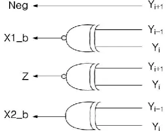
Fig 3.3 Booth-encoder execution logic input Y.
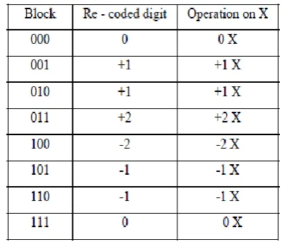
The encoding of the multiplier Y, using the modified booth algorithm, generates the following five signed digits, -2, -1, 0, +1, +2. Each and every encoded digit of the multiplier will multiplied with multiplicand, X, as illustrated in Table 3.1 and corresponding re-code generating gate-level logics in fig 3.3.
3.2 Partial Product Generator and Accumulator (PPA)
The PPA is execution block which performs multiplying operation between booth decode multiplier Y (booth x, booth 2x and negative) and multiplicand input X. Then the partial products are generated by performing AND between ‘X’ and ‘Y’ which are a 4 bit vectors as shown in fig 3.5. Suppose if we have 16-bit MBE multiplier Y and 16-bit multiplicand X we get NINE-partial products then the 1st partial product are stored in the accumulator ‘ppa’.
Similarly, the second and next partial products are stored in 9-PP-accumulators ‘ppb-ppi’.
Fig 3.4 Register transfer block of PPA.
Fig 3.5 PPG logic blocks.
Fig 3.6 Execution stages of PPA.
Finally the generated partial-product results are stored in accumulation section before going to accumulator as shown in above fig 3.6.
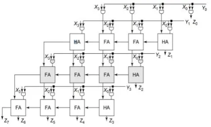
3.3 Compression (hybrid- CSA) Unit
Fig 3.7 The RTL of the compressor (CSA) unit.
Fig 3.8 Architecture of the proposed CSA tree.
Where,
Si signifies sign expansion.
Ni signifies compensate 1’s complement number into 2’s complement number.
S[i] signifies ith bit of the feedback sum
C[i] signifies ith bit of the feedback carry.
Z’[i] signifies previous result.
Pj[i] signifies ith line bit of the jth partial product.
White square signifies Full Adder. Gray square signifies Half Adder.
Rectangular symbol with five inputs signifies 2-bit CLA with a carry input.
The fig 3.8 shows the hybrid-type CSA that castoff in projected MAC. It is likewise promising to use FAs to implement the CSA deprived of CLA. The CLA will not process the lower bits of the previously generated partial products makes the number of bits for the final adder will increase leads to degrade in the performance. For the numeral structure, the CSA procedures 1’scomplement, but suggested use of modified CSA array without sign extension. The biggest modification among ours and the others is the kind of data that is feedback for accumulation pointers to least number of inputs to the final adder.
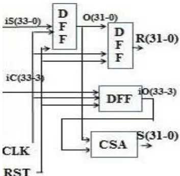
3.4 Final stage flip-flop and CSA
This final stage contains three delay-flip flops (DFF) and one carry save adder (CSA) for generation of multiplier result R(31:0) and sum(31:0) correspondingly. As exposed in fig 3.9 DFF are used for delay matching between most and least significant bits and CSA for adding carry iO(33:3) to sum results
S(31:0).
IV.
Design of High-Speed Booth Encoded
Parallel Multiplier
The booth encode multiplier by hybrid-CSA is designed in Xilinx ISE simulation tool. First we will write the Verilog codes for each block and then they are associated according to their execution order, the block arrangement is exposed in fig 4.1 and its RTL is exposed in fig 4.2.
Fig 4.1: MBE multiplier design.
Fig 4.2: Register-Transfer-Logic of MBE multiplier.
Fig 4.3 Execution steps in multiplier.
The execution movement of multiplying is presented in above fig 4.3 and the steps involves encoding of multiplier Y (32:0) in booth encoding section, partial product (ppa - ppi) generation and accumulation in PPA unit, summing of PP’s is done in compressor unit leads to generation of i-sum and i-carry and finally these are delayed and adding we get results R(X*Y) and sum and the internal assembly is exposed in fig 4.4.
Fig 4.4 Screenshot of suggested multiplier core structure.
V.
SIMULATION RESULTS
Fig 5.1 Simulation Results for reset 0.
Fig 5.2 Simulation Results for reset 1.
Fig 5.3 Power consumption report.
Equally we need to offer the reset RST value, based on the RST value the circuit is activated or
deactivated and below fig 5.1 and fig 5.2 designates results during RST 0 and RST 1 correspondingly.
From the result we conclude that this multiplier takes 1.9ps to process 16-bit inputs and to produce 32-bit
accomplished due to use of booth encoding technique beside with hybrid CSA circuit structure.
VI.
Advantages
a.
Low power consumesb.
High speedc.
Small in sized.
More densitye.
Less complexVII.
CONCLUSION
This paper focuses increasing the efficiency of the design of Multiplier with Radix-8 modified booth recoding with hybrid-CSA (carry save adder). By this, delay of complex arithmetic operations were reduced, also speeds of complex arithmetic calculations were increased. Here proposed concept was a structured technique for the direct booth encoding of multiplier and adder design leads to least number of inputs to final adding section. The proposed recoding schemes with high execution speed for 16x16-bit for signed and unsigned inputs, when they are incorporated in FAM designs, yield considerable performance improvements in comparison with the peak efficient recoding patterns.
VIII.
REFERENCES
1. A Amaricai, M. Vladutiu, and O. Boncalo, "Design issues and implementations for floating-point divide add fused," IEEE Trans. Circuits Syst. II-Exp. Briefs, vol. 57, no. 4, pp. 295-299, Apr. 2010. 2. E E. Swartzlander and H. H. M. Saleh, "FFT
implementation with fused floating-point operations," IEEE Trans. Comput., vol. 61, no. 2, pp. 284-288, Feb. 2012.
3. J J. F. Cavanagh, Digital Computer Arithmetic. New York: McGraw- Hill, 1984.
activity in FIR filters implemented by a MAC architecture," IEEE Trans. Comput.Aided Des. Integr. Circuits Syst., vol. 19, no. 1, pp. 164-169, Jan. 2000.
5. O Kwon, K. Nowak, and E. E. Swartzlander, "A 16-bit by 16-bitMAC design using fast 5: 3 compressor cells," J. VLSI Signal Process. Syst., vol. 31, no. 2, pp. 77-89, Jun. 2002.
6. L-H. Chen, O. T.-C. Chen, T.-Y.Wang, and Y.C. Ma, "A multiplication- accumulation computation unit with optimized compressors and minimized switching activities," in Proc. IEEE Int, Symp. Circuits and Syst., Kobe, Japan, 2005, vol. 6, pp. 6118-6121.
7. Y-H. Seo and D.-W. Kim, "A new VLSI architecture of parallel multiplier-accumulator based on Radix-2 modified Booth algorithm," IEEE Trans. Very Large Scale Integr. (VLSI) Syst., vol. 18, no. 2, pp. 201-208, Feb. 2010.
8. APeymandoust and G. de Micheli,"Using Symbolic algebra in algorithmic level DSP synthesis,"in Proc.Design Automation Conf.,Las Vegas,NV,2001,pp.277282.
9. W-C.Yeh and C.-W.Jen,"High-speed and low power split-radix FFT,"IEEE Trans.Signal Process.,vol 51,no. 3,pp.864-874,Mar.2003.
10. C. N. Lyu and D. W. Matula," Redundant binary booth recoding, in Proc. 12th Symp. Computer. Arithmetic, 1995, pp. 50-57.
Author’s Profile
C V Madhu Kumar pursuing M.Tech degree in VLSI System Design at the department of ECE in Kuppam
Engineering College, Kuppam
affiliated to JNTU, Ananthapur. He obtained the B.Tech degree in Electronics and
Communication Engineering from Sir Vishveshwaraiah Institute of Science and Technology, Madanapalle, affiliated to JNTU Ananthapur. He is doing his M.Tech project on Modifield Booth multiplier under the guidance of Dr. G N Kodanda Ramaiah &
Dr. K Rasadurai. His areas of interests are Electronics, Analog and Mixed Signal Circuit Design, Digital IC Design and Semiconductor Device Modeling.
Email: [email protected]
Dr. G N Kodanda Ramaiah is a Professor and HOD of Electronics and Communication Engineering in
Kuppam Engineering College,
Kuppam affiliated to JNTU
Ananthapur. He obtained the B.E
degree in Instrumentation & Technology and M.Tech degree in Bio Medical Instrumentation from Sri J C College of Engineering, Mysore affiliated to Mysore University. He obtained Ph.D. in Signal Processing from JNTU Ananthapur. His areas of interests are Embedded System, IOT, AI, speech processing and signal processing.
Dr. K Rasadurai is Professor,
SPOC-SWAYAM NPTEL at the
department of Electronics and
Communication Engineering in
Kuppam Engineering College,
Kuppam affiliated to JNTU
Ananthapur. He obtained the B.E
degree in Electronics and Communication Engineering from Anna University, Chennai, M.Tech degree in Embedded Systems from Anna University, Chennai and Ph.D. in Wireless Communication from Anna University, Chennai. He presented 9 International Conferences and published 8 International Journals. His areas of interest are Wireless Networks and mobile communication.
Mobile Phone : 9442316011 Email: [email protected]