http://www.sciencepublishinggroup.com/j/ajmsp doi: 10.11648/j.ajmsp.20170203.12
Parametric Studies and Numerical Analysis of Low Velocity
Impact on Smart Hybrid Composite Laminates
Abdul Nazeer
1, *, Syed Kashif Hussain
1, Asif Iqbal M. Doddamani
21
Department of Mechanical Engineering, Khaja Bandanawaz College of Engineering, Gulbarga, India
2
Department of Mechanical Engineering, SECAB Institute of Engineering & Technology, Bijapur, India
Email address:
[email protected] (A. Nazeer), [email protected] (S. K. Hussain)
*
Corresponding author
To cite this article:
Abdul Nazeer, Syed Kashif Hussain, Asif Iqbal M. Doddamani. Parametric Studies and Numerical Analysis of Low Velocity Impact on Smart Hybrid Composite Laminates. American Journal of Materials Synthesis and Processing. Vol. 2, No. 3, 2017, pp. 41-50. doi: 10.11648/j.ajmsp.20170203.12
Received: September 7, 2016; Accepted: June 15, 2017; Published: July 31, 2017
Abstract:
To evaluate the effect of low velocity impact on composite plate using nonlinear explicit finite element software LS-DYNA software. The theoretical basis of the present finite element model is verified by analyzing impact-loaded laminated composite plate previously been studied through analytical. The study of hybrid composite plates are carried were the SMA (shape memory alloy) are used in between the plies to increase the resistance. Also parametric studies were done to find the importance of the Mesh. The present numerical approach is successfully demonstrated through comparisons between experimentally-measured and computed force-time histories for impact of carbon fiber-reinforce plastic (CFRP) plates. Parametric studies are also conducted by varying Mesh results obtained are correlated with the results in the published literature.Keywords:
SMA, CFRP, Ls Dyna, Hypermesh, Low Velocity Impact, Belytschko-Tsay1. Introduction
Composite materials are used in many engineering applications Advance material with high stiffness and high strength such as carbon/epoxy graphite/epoxy and kevler/epoxy are now widely used in as structural material in aerospace industries and material transport purpose. The high-stiffness, high-strength and low-density characteristics make composites highly desirable in primary and secondary structures. The Boeing 777 for example, uses composites in fairings, floor beams, wing trailing edge surfaces and the empennage. The strongest sign of acceptance of composites in civil aviation is their use in the new Boeing 787 “Dreamliner” and the world’s largest airline the Airbus A380.
1.1. Belytschko-Tsay
The most frequently used shell element is the so called Belytschko-Tsay element. It was first implemented in LS-DYNA as a computationally more efficient element than its precursor. It is considerably more efficient than the other
types of shells and this advantage depends on several mathematical simplifications. However, because of these simplifications, it has some disadvantages. It looses stiffness considerably when it is warped and it is therefore not appropriate for analysing warped structures. Since only one integration point in the plane is used, zero energy modes may occur.
a. Very fast and is recommended for most applications b.Uses reduced integration (one point)
c. Should not be used when elements experience excessive warping
1.2. Fully Integrated Belytschko-Tsay Elements
a. 2.5 times slower than reduced integration Belytschko-Tsay shell.
b.Has four integration points in plane and does not need hourglass control.
c. Shear locking is remedied by assumed strain for the transverse shear.
American Journal of Materials Synthesis and Processing 2017; 2(3): 41-50 42
1.3. Morphology of Low Velocity Impact Damage
For impact loading which does not result in complete penetration of the structure studies indicate that damage morphology consists of de-laminations, matrix cracking, and fiber failures. Delamination which is the debonding between adjacent laminas is of most significance because it drastically reduces the strength of the laminate structure. For a laminate impacted on its top surface at the interface between plies with different fiber orientations the delaminated area has an ‘oblong’ or ‘peanut’ shape with its major axis oriented in the direction of the fibers in the lower ply at that interface. The nature and the shape of delamination are quite irregular and that their orientations become rather difficult to ascertain
2. Modelling and Analysis of Smart
Hybird Composite Embedded with
Shape Memory Alloys Wire (SMA)
and Rigid Impactor
Table 1. Material Properties of Composite plate [2].
Material Property for plate Symbol (unit) Value
Young’s modulus in fibre direction E11 (Gpa) 32.062
Young’s modulus in transverse direction E22 (Gpa) 10.789
Young’s modulus E33 (Gpa) 10.789
Shear Modulus G12 (Gpa) 11.92
Shear Modulus G13 (Gpa) 11.92
Shear Modulus G23 (Gpa) 4.68
Material Property for plate Symbol (unit) Value
Poisson’s Ratio γ12 (Gpa) 0.344
Poisson’s Ratio γ13 (Gpa) 0.344
Poisson’s Ratio γ23 (Gpa) 0.344
Density Ρ (kg/mm3) 1.796e-6
Table 2. Material Properties of Rigid Sphere [2].
Material property for Impactor Symbol (units) Value
Radius R (mm) 6.35
Young’s modulus E (Gpa) 207
Mass M (kg) 1.5
Poisson’s Ratio γ 0.3
Density ρ (kg/mm3) 7.8e-6
Velocity V (mm/ms) 2
Table 3. Material Properties of SMA wires [2].
Material property of SMA wires Symbol (units) Value
Young’s Modulus E (Gpa) 70
Poisson’s Ratio γ 0.33
Density ρ (kg/mm3) 6.5e-6
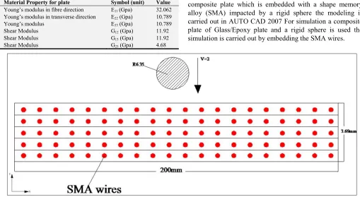
2.1. Geometrical Modeling of a Rigid Sphere and Hybrid Composite Plate
Figure 1 shows the geometric modelling of a hybrid composite plate which is embedded with a shape memory alloy (SMA) impacted by a rigid sphere the modeling is carried out in AUTO CAD 2007 For simulation a composite plate of Glass/Epoxy plate and a rigid sphere is used the simulation is carried out by embedding the SMA wires.
Figure 1. Geometrical modeling of a rigid sphere and hybrid composite plate.
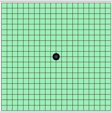
2.2. Finite Element Modelling of Smart Hybrid Composite Plate
Figure 2 shows the finite element modeling of a glass/epoxy laminated composite plates and rigid sphere the analysis is carried on smart hybrid composite plate embedded with a shape memory alloy (SMA) wires. The modeling of
Figure 2. Finite Element model of the smart hybrid composite plate and rigid sphere.
2.3. Analysis of Low Velocity Impact on Smart Hybrid Composite Plate Embedded with Shape Memory Alloy (SMA) Wires
In these case the low velocity impact analysis is carried on a square laminates of (200x200x2.69mm) consisting of unidirectional layers are considered. The SMA wires are
embedded within the different layers of the laminate symmetrically to generate a smart hybrid composite structure. Geometrical and material properties of the composite plate as well as the impactor and SMA wires are presented in respectively.
American Journal of Materials Synthesis and Processing 2017; 2(3): 41-50 44
Figure 4. Comparison force vs time of Present result with shokuhfar [2].
Figure 3 illustrate the damage caused to the smart hybrid composite plate embedded with SMA wires. Due to impactor with mass of 1.5kg and velocity of 2mm/ms. The yellow and green region shows the maximum stress condition at time 2.3ms. As seen from the Figure 4 the maximum contact force obtained with a sphere of mass 1.5kg and velocity of 2mm/ms is 7.6kN at time 2.1ms. Due to continuous loading beyond that point there is a continuous progression of damage to the fibers through the thickness of structure which increases with impact load till time t=2.1 (approx). when there is permanent damage caused to the structure then reduction in the impact force is observed.
Table 4. Comparison of FEM and Experimental Peak force.
RESULTS PEAK IMPACT FORCE (kN)
Shokuafur 7.52
Present 7.6
With the implementation of SMA wires in the composite plate. It was shown that if the SMA wires embedded inside of the unidirectional hybrid composite plate, the global behavior of the structure against the impact would be improved. Therefore, the structure with the SMA wires damps more uniformly and rapidly than the plate without the SMA wires
after the impact. It improves the impact response of the traditional polymer composite structures, and improve the impact resistance of these structures the most.
3. Modeling & Analysis of the Finite
Element Model of Laminated
Composite Plate and Steel Sphere
Created in L. S Dyna 971 Version for
Different Mesh Density
Figure 5. Finite Element model of laminated composite plate and steel sphere.
4. Result and Discussion
Once the model was made in Msc/Pattern and the key file was edited the model was run on a solver for solving the given loading and boundary constraints. The results were studied in L. S-prepost as solver and compared with the results in the literature and good co-relation was found between the simulation and results of Vaziri [1].
The analysis is carried out on a quarter plate by varying the mesh size in plate starting from the mesh of 1x1, 2x2, 4x4,
and 5x5 to obtained the good co-related result.
Although one element approximation of the entire plate resulted in a very good the transient response calculated in this case was found to be stiffer than those obtained using finer meshes. This is because a single element cannot model the higher modes of vibration adequately. Figure 5 shows that a one element representation of a quarter plate (or 2 x 2 elements for the whole plate) can predict the transient response of the plate quite well. However the curve which is closest to the analytical predictions of Vaziri [1].
American Journal of Materials Synthesis and Processing 2017; 2(3): 41-50 46
From the figure 6 the impact force and profile time nearly same for both experimental and fem results for loading only The nature of graph from fem matches from closely with that of analytical prediction of impact load vs time for 4x4 and 5x5 mesh in plate. A higher contact force induced higher contact loading at the impact point for impactor velocity 3mm/ms. Note that from the fem simulation it was observed that the maximum stress condition was not immediately under the impact point but located off from the impact point.
As seen from the Figure 6 the maximum contact force for 1x1 element size is 0.68 at time 0.036. Due to continuous loading beyond that point there is a continuous progression of damage to the fibers through the thickness of structure which increases with impact load until time t=0.036 (approx) as seen from the Figure 6 Where there is permanent damage caused to the structure and thus reduction in the impact force. Therefore the major mode of failure for this impact loading scenario was due bending stress produce in the bottom laminate which is carried to the delamination which in turn there is reduction in the strength of composite plate which in turn causes reduction in load carrying capacity of the plate. The damage in structure started with Matrix cracks since the strength properties of matrix were much less than Carbon fibers.
Then mesh of the quarter plate is refined it to 2x2 and the maximum contact force is 0.31KN at time 0.046 (appox), the result obtained is closely matches to the analytical predicted result but the obtained contact force is less than that obtained by pierson and vaziri. In order to analyze the result more accurately the meshing of the plate is refined more to 4x4 mesh density and the obtained result matches well with the analytical predicted value by pierson and vaziri. similarly for mesh size 5x5 the contact force is 0.336KN at time 0.058ms (approx) and it is seen the curve which is closest to the analytical predictions of pierson and vaziri is obtained by using the finer mesh mesh (4x4 and 5x5 elements for a quarter plate.
Table 5. Comparison of FEM and Experimental Peak force.
Mesh Size
FEM Simulation Peak Impact Load (kN)
Experimental Simulation Peak Impact Load (kN)
1x1 0.68 0.605
2x2 0.31 0.358
4x4 0.338 0.327
5x5 0.336 0.327
5. Study of Parameters That Affects the
Damage Process
Once the proposed FEM model results were validated with corresponding experimental results a parametric study was done on the same model with existing boundary condition and geometry the studies included various parameters impactor material property, lay-up sequence, impactor velocity and boundary conditions that affects the impact damage process.
5.1. Effect by Changing the Material of Impactor
To study the effect of changing material properties of
impactor. but by changing material of impactor from steel to aluminum the diameter of sphere is kept same 12.7mm and the impactor velocity 2.68mm/ms and mass of the impactor is 6.14kg and all other properties are kept same. The material model assign in L. S. DynaPLASTIC_KINEMATIC (MAT_003) Difference was observed in the nature of results for contact force vs time with steel and aluminum projectiles. The peak force from steel impactor was 11.9kN (approx) where from aluminum was 9.02kN (approx) as illustrated in Figure 7.
Figure 7. Comparison of Contact Force for steel and aluminum impactor.
Figure 7 shows the comparison of contact force of a steel impactor and a aluminium impactor by keeping the constant velocity and same material and boundary conditions for the target plate the difference obtained is due to change in the Young’s modulus of impactor. The maximum contact force obtained by steel impactor is 11.9 kN and by aluminium impactor is 9.02kN as seen in figure 7.
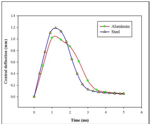
Figure 8. Comparison of central deflection when impacted by a steel and aluminum impactor.
gives a higher contact stiffness which induces higher contact forces and a smaller contact zone. The maximum deflection is seen with steel impactor as compared to aluminum impactor. Shows comparison of peak values of impact force for steel and aluminum impactor.
Table 6. Comparison of peak force for different material of impactor.
IMPACTOR MATERIAL PEAK IMPACT FORCE (kN)
Steel 11.9
Aluminum 9.02
5.2. Effect by Varying the Lay-up Sequence
Another part of the current parametric study examined
how the difference in angle between of two plies affects the impact damage process. In this simulation four lay-up sequence was modeled with same boundary condition and using impactor velocity of V=2.68mm/ms the lay-up configuration for angle ply, anti-symmetric, cross ply symmetric, laminates are as shown in Table 7.
Table 7. Four lay-up sequence of laminates.
LAY-UP NUMBER SEQUNCE NAME LAY-UP
Lay-up 1 Angle-Ply [-45/45/-45/45]3s
Lay-up 2 Anti-symmetric [45/60/-60/-45]3s
Lay-up 3 Cross-ply [0/90/0/90]3s
Lay-up 4 Symmetric [0/30/60]4s
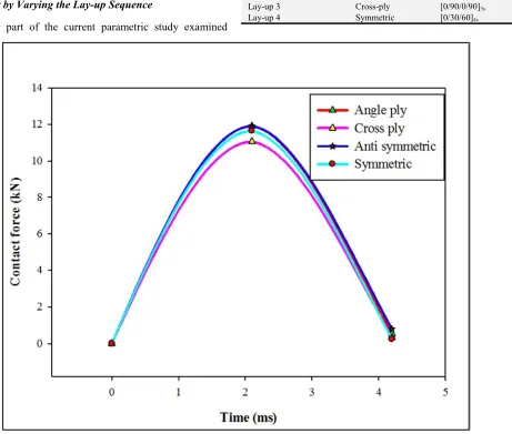
Figure 9. Comparison of contact force vs time for different lay-up sequnce.
Figure 9 shows the number of non-similar ply interfaces for lay-ups LAY-UP 1, 2, 3 and 4. From the Figure 9 the peak force (P.F) for LAY-UP 2 was greater than LAY-UP 1, 3 and 4 (P.F)2>(P.F)1>(P.F)4>(P.F)3. This can be explained by the fact that the greater the interfaces the less is the damage caused and better is the compressive after impact strength property and more is the energy absorbing capacity of the laminate structure. Therefore a laminate structure with more interfaces will have better impact resistance. Figure 9 shows the comparison of peak impact force for different lay-up sequences and impact velocity 2.68mm/ms.
Table 8. Comparison of peak force for different lay-up.
Lay-up sequence Peak force (kN)
[-45/45/-45/45]3s 11.90
[45/60/-60/-45]3s 11.91
[0/90/0/90]3s 11.06
[0/30/60]4s 11.63
5.3. Effect by Changing the Boundary Condition of Plate
American Journal of Materials Synthesis and Processing 2017; 2(3): 41-50 48
properties as that of experimental data with velocity of 2.68mm/ms was used. The two boundary conditions studied was the one that of the experimental set up i.e simply supported condition and the other was clamped boundary
condition. The impact force for both boundary condition for a laminated composite plate of lay-up sequence [45/90/-45/0]3s
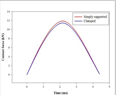
as shown in figure 10 below.
Figure 10. Contact force history for with different boundary condition.
As it can be seen from the Figure 10 the impact force for clamped boundary condition is less that for simply supported boundary condition. This is because in clamped boundary condition the plate is constrained in x, y and z direction therefore there is no vibration at ends of the plate. Where as in simply supported boundary condition the plate is constrained only in y- direction.
Table 9. Comparison of peak force for different boundary condition.
Support type Peak force (kN)
Simply supported 11.9
Clamped 11.46
5.4. Effect by Changing the Thickness of Plate
The impact response of composite laminates changes significantly as the laminate thickness increases. The reason of this behavior is the flexural and contact stiffness varying according to thickness and thereby, causing the impact behavior of a structure to change. Therefore, it is important to determine the impact response of laminated CFRP laminated composite plates with respect to thickness. In the present thesis, lay-up of CFRP laminates are [45/90/-45/0]3s. Two
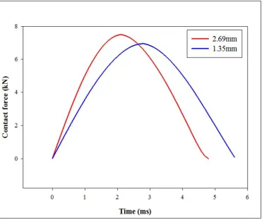
nominal thicknesses with averages of 1.35 mm and 2.69 mm are used for analyzing the thickness effect. 1.35mm specimens are called thin laminates while the 2.69 mm specimens are considered as thick laminates.
Figure 11 shows the impact characteristics of both thick and thin laminates. It can be concluded that the higher the thickness of the composite laminate, the higher the peak force. But the contact time duration decreases with the increasing thickness. This behavior is essentially the same for all the laminated plate dimensions.
In fact, the result that higher the thickness of the specimens has higher peak forces coincides with the fact that the higher thickness of the laminates the stiffer the composite laminate and the dynamic response, such as the impact force, is greatly influenced by the thickness. The maximum contact force reached by changing the thickness of plate is as shown as in Figure 11
Table 10. Comparison of peak force for different thickness of plate.
Thickness (mm) Peak force (kN)
2.69 7.50
Figure 11. Comparison of contact force history for two different thickness.
6. Conclusion
In the present research numerical model was developed so that the effect of low-velocity impact upon the smart hybrid composite structures demonstrated. It was shown that if the SMA wires embedded inside of the unidirectional hybrid composite plate, the global behavior of the structure against the impact would be improved the structure with the SMA wires damps more uniformly and rapidly than the plate without the SMA wires. The one who uses the SMA wires to improve the impact response of the traditional polymer composite structures, he can improve the impact resistance of these structures the most
The analysis is carried out on CFRP plate. The result obtained after the analysis of CFRP plate with different mesh density. The contact force is calculated at the centre of the plate and the results are plotted in Figure 6. Although one element approximation of the entire plate resulted in a very good estimate the transient response calculated in this case was found to be stiffer than those obtained using finer meshes. This is because a single element cannot model the higher modes of vibration adequately. Figure 6 shows that a one element representation of a quarter plate (or 2 x 2 elements for the whole plate) can predict the transient response of the plate quite well. However, the curve which is closest to the analytical predictions of Vaziri [1] is obtained by using the finer mesh (i.e. 4 x 4 and 5x5 elements for a quarter plate). so it has been observed that mesh density is
refined the accuracy is improved. The obtained result are matching well with the results of Vaziri [1].
References
[1] Vaziri. R, Quan. X and Olson. M. D “Impact analysis of laminated composite plates and shells by super finite elements Int. J. Impact Enon 9 Vol. 18, Nos 7 8, pp. 765-782, 1996.
[2] Shokuhfar. A, “Analysis and optimization of smart hybrid composite plates subjected to low-velocity impact using the response surface methodology (RSM)” Thin-Walled Structures 46 (2008) 1204–1212.
[3] SADIGHI. M, H. POURIAYEVALI, SAADATI. M “Response of fully backed sandwich beams to low velocity transverse impact” World Academy of Science, Engineering and Technology 36 2007.
[4] Hosur. M. V, “Studies on the low-velocity impact resip/;ponse of woven hybrid composites” Composite Structures 67 (2005) 253–262.
[5] Ik Hyeon Choi, “Low-velocity impact analysis of composite laminates using linearized contact law” Composite Structures 66 (2004) 125–132.
[6] Liu. G. R and Quek. S. S “The finite element method A practicle course”.
American Journal of Materials Synthesis and Processing 2017; 2(3): 41-50 50
[8] Tiebreak. R. a, Bachene. M b, Rechak S. c, Necib. B “Damage prediction in composite plates subjected to low velocity impact” Composite Structures 83 (2008) 73–82.
[9] Shiuh-Chuan Her, “The finite element analysis of composite laminates and shell structures subjected to low velocity impact” Composite Structures 66 (2004) 277–285.
[10] Zuleyha Aslan “The response of laminated composite plates
under low-velocity impact loading” Composite Structures 59 (2003) 119–127.
[11] Krishnamurthy. K. S, “A parametric study of the impact response and damage of laminated cylindrical composite shells” Composites Science and Technology 61 (2001) 1655– 1669.
![Figure 4. Comparison force vs time of Present result with shokuhfar [2].](https://thumb-us.123doks.com/thumbv2/123dok_us/8466684.1710093/4.595.75.525.76.408/figure-comparison-force-vs-time-present-result-shokuhfar.webp)
![Figure 6. Comparison of Present result with Published results for force vs time [1].](https://thumb-us.123doks.com/thumbv2/123dok_us/8466684.1710093/5.595.149.448.71.354/figure-comparison-present-result-published-results-force-time.webp)