http://www.sciencepublishinggroup.com/j/ijmsa doi: 10.11648/j.ijmsa.s.2018070101.11
ISSN: 2327-2635 (Print); ISSN: 2327-2643 (Online)
Vibration Analysis of Layered Composite Beam According
to Wind Turbine Blades of Variable Cross - Section
Ceyda Okta
1, Gökmen Atlıhan
2, Ö. Altan Dombaycı
1, *1Department of Material Science and Engineering, Faculty of Technology, Pamukkale University, Kinikli, Denizli, Turkey 2
Department of Manufacturing and Mechanical Engineering, Faculty of Technology, Pamukkale University, Kinikli, Denizli, Turkey
Email address:
[email protected] (Ö. A. Dombaycı)
*Corresponding author
To cite this article:
Ceyda Okta, Gökmen Atlıhan, Ö. Altan Dombaycı. Vibration Analysis of Layered Composite Beam According to Wind Turbine Blades of Variable Cross – Section. International Journal of Materials Science and Applications. Special Issue: Energy and Materials II.
Vol. 7, No. 1-1, 2018, pp. 1-7. doi: 10.11648/j.ijmsa.s.2018070101.11 Received: July 3, 2017; Accepted: July 10, 2017; Published: August 2, 2017
Abstract:
In this study, for wind turbine blades of variable cross-section vibration analysis of composite beams has beeninvestigated analytically and numerically. Bernoulli composite beam theory used in the analytical part of the beam and the effect of the shear force from the beam has been neglected. A composite beam was created from layers 8. In the numerical part of the study, using finite element method and ANSYS program were used. As result of calculations, without changing the geometry of the beam, it is observed that the natural frequency can be changed by changing the layer angle of the stratified composite beam.
Keywords:
Wind turbine Blade, Material of Composite, Mechanicial Vibrations1. Introduction
The development of awareness of climate change, caused the largest increase in renewable energy use. This awareness, along with located between renewable energy sources, Wind Energy has gained momentum, world energy production by 2020 and 10% of it is estimated that would be covered by wind energy [1]. Since the beginning of 2000, Wind Energy has been the fastest growing renewable energy source in the world. In 2013, wind energy % 20.7% growth in renewable energy accounted for more than half of the growth. The world of electricity and 3% from wind power is obtained. China's total wind capacity up 31% owner. In 2012 Denmark's electricity production in Spain and 20% in Ireland, 17% Germany, % 7.7% obtained from wind energy. Today, the 7.5 MW turbines can be made. 6,500,000 kWh of electricity from 2.5 MW wind turbine is obtained in the years [2].
Wind turbines used to capture wind energy in the flow in the atmosphere. This energy is converted into electrical energy with wind turbine blades. Of the wind turbine rotor blades, turbine critical parts of the system [3]. In recent
years, the rapid growth of wind power, together with longer and more flexible blades, wind turbines have been developed [4]. It has a capacity different size wind turbines. Considering all the turbine structure, can be divided into two types: speed-increasing gear box type and direct-driven type [5].
From wind energy to mechanical energy conversion efficiency, is dependent on the optimum design of wind turbine blades. The simulation of flow around a wing and the aerodynamic conditions for the estimation of characters, it is quite important to make the design work [6]. In the design of wind turbines, the unsteady aerodynamic loads due to unsteady nature of the environment and accurate estimation is critical. Dynamic stall Unsteady aerodynamic loads are usually calculated using the model. Wing vibrations, the angle of attack of the wing which changes the dynamic factors. The vibration of the wing at the same time, the influence on power generation is great. Therefore, in the wings of the wind turbine technology has become an important issue in reducing the vibration [7-8].
beam and the effect of the shear force from the beam has been neglected. A composite beam was created from layers 8. In the numerical part of the study, using finite element method and ANSYS program were used. The generated beams have the same geometry in the finite element model of composite beam the composite beam acting on the angle of inclination of the vibration is demonstrated numerically and analytically.
2. Materials and Methods
2.1. Analytical Analysis of the Composite Beam
The normal stress in jth layer of a composite laminated beam shown in Figure 1 can be written in the following way [9];
(1)
Figure 1. A composite laminated beam.
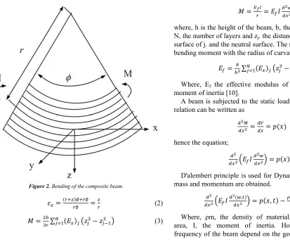
Bernoulli-Euler hypothesis is tilted (Figure 2) at a certain distance from the neutral surface strain;
Figure 2. Bending of the composite beam.
∅ ∅
∅ (2)
∑ (3)
where r, the radius of curvature. The relationship between normal stress and bending moment can be written as;
!
" (4)
where, h is the height of the beam, b, the width of the beam, N, the number of layers and zj. the distance between the outer
surface of j. and the neutral surface. The relationship between bending moment with the radius of curvature.
#
$%∑ (5)
Where, Ef the effective modulus of the beam, I is the
moment of inertia [10].
A beam is subjected to the static load torque load for that relation can be written as
"& "
"'
" ( ) (6)
hence the equation;
" " *
"!
" + ( ) (7)
D'alembert principle is used for Dynamics load by adding mass and momentum are obtained.
" " *
"
!,-" + ( ), .
/01" !
,-"- (8)
depend on material properties and the applied force. So p (x. t) can be taken as zero. Thus, the equation takes the following form.
" " *
" !,-" + 2
/01" !
,-"- 0 (9)
This equation homogeneous equations and boundary conditions in the vertical direction and the coordinates of deflection, which provides time-dependent harmonic components.
4 ), . ∑?6 567896:; <=7>6. (10)
Where, An, the amplitude and ωn, natural frequency of the
n mode of the moment.
A variable beam cross-section is shown Figure 3.
Figure 3. The beam with variable cross section.
As can be seen from Figure 3 variable cross section is defined by means of a function f (x) [11]. ɵ is the taper angle, β is the variable cross-section parameter, hx is the semi
thickness according to x, h1 is the maximum half thickness
and the thickness h2 is the minimum half-thickness;
@ @ A1 CD ) E (11) C *1 $$F+ (12)
and
D ) ; (13)
According to the selected function of the moment of inertia I is calculated.
2.2. Numerical Analysis of Composite Beam
A complex problem by the finite element method, known or easier to comprehend sub-divided into problems, is made more understandable. The sub-problems are solved by combining the solution to the original problem. The three basic qualities of the method. First, geometrically complex finite element solution in the region of the so-called geometrically simple sub-divided into regions. Second, in each element, continuous functions, algebraic polynomials can be defined as a linear combination of the accepted. Third, the particular constant value in each element definition of the equation of the callee points (nodes) is sufficient for solving the problem of obtaining the values of.
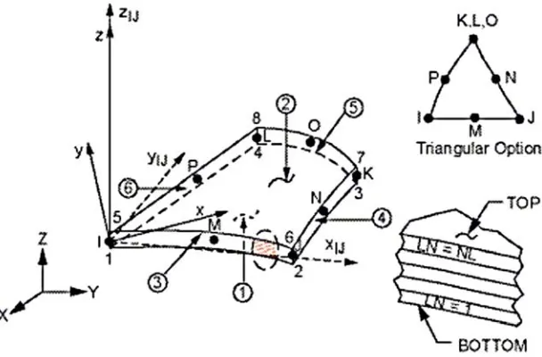
The finite element method (fem) that use many computer programs. ANSYS is one of the best known of these diagnoses [12]. In this study has been identified as a priority in elemet type. The vibration of the element to be analyzed, the layered, composite must have the properties. Shell 99 element that provides these features were selected. Structural Shell 99 layered shell models can be used for up to 250 and the layer allows this to work. This element, X, Y, Z directions of rotation and displacement by a 6-degrees of freedom is fixed. Orthotropic materials are used. Shell 99 (Figure 4), while cubic or triangular element in the mesh are made of the elements can be divided into parts. Table 1 geometric and material properties of the beam generated are given.
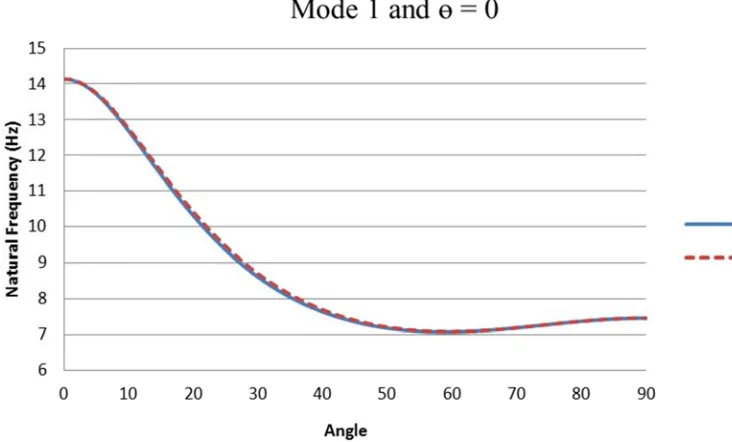
Figure 5. Variation of natural frequency with stacking sequence for mode 1 and ɵ = 0.
Table 1. Material properties and dimensions of the laminated composite beam.
Properties Symbol Present
Longitudinal elasticity modulus (MPa) 44150 Transverse elasticity modulus (MPa) 12300
Shear modulus G (MPa) 4096
Poisson’s ratio H 0.2
Length I(mm) 400
Height @ (mm) 3
Width J(mm) 20
The cross section of the composite beam the angle of ɵ=0, while the angle of the beam shows the effect of the natural frequency of the layer. As shown in Figure 5, the angle of orientation of the composite beam reaches its highest value at the angle of zero degrees and then the frequency quickly decreased. The decrease of this frequency to 58° and the lowest frequency value was found at this angle. The inrease of the natural frequency of the composite beam from 59 degrees to 90 degrees is observed. Both numerical results and the analytical results were also close to each other.
Figure 6. Variation of natural frequency with stacking sequence for mode 2 and ɵ = 0.
Figure 7. Variation of natural frequency with stacking sequence for mode 3 and ɵ = 0.
In Figure 7, the angle of orientation of the composite beam reaches its highest value at zero degrees and the frequency quickly decreased. The decrease of this frequency to 60° and the lowest frequency value was found at this angle. The inrease of the natural frequency of the composite beam from 61 degrees to 90 degrees Mode 1 and Mode 2 in Mode 3 when compared with larger frequency values were obtained. Both numerical results and the analytical results were also close to each other.
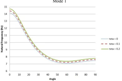
Figure 8. The layer of the natural frequency of laminated composite beams according to the angle of change (mode 1).
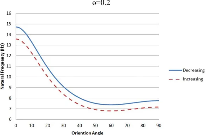
Figure 9. The increasing and decreasing cross-section according to the natural frequency of laminated composite beams according to the angle of the layer change (mode 1).
The cross section of the composite beam the angle of ɵ=0.2 while the angle of the beam shows the effect of the natural frequency of the layer. As shown in Figure 9, orientation of the composite beam reaches its highest value at the angle of zero degrees and the frequency quickly decreased. Laminated composite beam cross-section varies based on whether it is decreasing or increasing the frequency of the beam is observed. It is seen that a larger frequency value reaches a descending beam geometry.
3. Results and Discussions
For wind turbine blades of variable cross-section vibration analysis of composite beams has been investigated analytically and numerically. Laminated composite beams, fiber orientation angle with the change of vibration of the beam without changing the geometry by showing that you know degistirile it is shown that vibration can vary. Boundary conditions with built-in cross section of the beam if the beam is composite of natural frequencies of ascending or descending has been shown to be affected. However;
a) The maximum values of frequency of the composite beam is 0°.
b) It has been observed that the value of frequency drops from 0° to 50°.
c) A slight increase in frequencies of the composite beam in terms of orientation, the next 60° are observed.
d) The numbers of mode of increase, it was observed that the residue frequencies increase of the beam mode.
e) Increase the cross section of the composite beam with the angle of ɵ, the residue of the natural frequency increase was observed.
f) The laminated composite beam cross-section varies based on whether it is decreasing or increasing the frequency
of the beam is observed. It is seen that a larger frequency value reaches a descending beam geometry.
g) Without changing the geometry of the beam, it is observed that the natural frequency can be changed by changing the layer angle of the stratified composite beam.
Nomenclature
: Normal Stress (N/mm2) : Normal Strain
: Young Modulus (N/mm2) r: Radius of curvature (mm) h: height of the beam (mm) b: width of the beam (mm) N: number of layers
zj: distance between the outer surface of j. and the neutral
surface (mm)
M: Bending moment (Nmm)
Ef: the effective modulus of the beam (N/mm2)
I: the moment of inertia (mm4) ρm: the density of material (kg/m3)
A: the cross-section area (mm2) An: amplitute
ωn: Natural frequency (hz)
hx: the semi thickness (mm)
h1: the maximum half thickness (mm)
h2: the minimum half thickness (mm)
β: the variable cross-section parameter L: the beam lenght (mm)
ɵ: the taper angle (dgree)
E1: Longitudinal elasticity modulus (N/mm2)
E2: Transverse elasticity modulus (N/mm2)
G12: Shear modulus (N/mm2)
References
[1] A. Abouhnik, A. Albarbar “Wind türbine blades condution assessment based on vibration mesurements and the level of an empirically decomposed feature”, Energy Conversion and Management 2012,64: 606-613.
[2] S. Erdoğan, “Energy Politics of Turkey” Orion, Ankara, 2117. [3] A. Joshuva, V. Sugumuran “A data driven approach for
condition monitoring of wind türbine blade using vibration signals through best-first tree algorithm and functional trees algorithm: A comparative study”, ISA Transactions 2017, 67: 160-172.
[4] X. Liu, C. Lu, S. Liang, A. Godbole, Y. Chen, “Influence of vibration of large-scale wind türbine blade on the aerodynamic load”, Energy Procedia 2015, 75: 873-879. [5] W. Liu, “The vibration analysis of wind türbine
blade-cabin-tower coupling system”, Engineering Structures 2013, 56: 954-957.
[6] R. B. Mahadisha, S. A. Kale, “Effect of leading edge Radius
and blending distance from leading edge on the aerodynamic performance of smart wind türbine blade airfoils”, International Journal of Energy and Power Engineering 2015, 4: 54-58.
[7] X. Liu, C. Lu, S. Liang, A. Godbole, Y. Chen, “Vibration- induced aerodynamic loads on large horizontal axis wind türbine bladses” Applied Energy, 2017, 185: 1109-1119. [8] B. Fitzgerald, B. Basu, “Cable connected active tuned mass
dampers for control of in – plane vibrations of wind türbine blades”, 2014, 333: 5980-6004.
[9] Atlihan G, Vibration analysis of the delaminated composite beams, Ph. D. Thesis, Pamukkale University, Denizli, Turkey, 2010, 50-95.
[10] R. F. Gibson, “Principles of composite material mechanics”, Philadelphia, USA, 1994.