Published online October 30, 2014 (http://www.sciencepublishinggroup.com/j/jenr) doi: 10.11648/j.jenr.20140305.11
ISSN: 2330-7366 (Print); ISSN: 2330-7404 (Online)
Effect of the shape surface of absorber plate on
performance of built-in-storage solar water heater
Omer Khalil Ahmad, Ahmed Hassan Ahmed, Obiad Majeed Ali
Technical institute of Hawija, Foundation of technical education, Baghdad, Iraq
Email address:
[email protected] (O. K. Ahmed), [email protected] (A. H. Ahmed), [email protected] (O. M. Ali)
To cite this article:
Omer Khalil Ahmad, Ahmed Hassan Ahmed, Obiad Majeed Ali. Effect of the Shape Surface of Absorber Plate on Performance of Built-in-Storage Solar Water Heater. Journal of Energy and Natural Resources. Vol. 3, No. 5, 2014, pp. 58-65.
doi: 10.11648/j.jenr.20140305.11
Abstract:
An experimental and numerical study was carried out on a storage solar collectors to verify its suitability for domestic use. These storage collectors can be used as storage water tanks to replace the ordinary cubical or cylindrical tank commonly used in Iraqi houses. The paper includes study the effect of the shape surface of absorber plate on performance of storage solar collector by construction of three-box type, built –in-storage water heaters with three different shape of front absorber plat, flat, wavy, and zigzag shapes. Experiments were conducted in summer and autumn seasons, and the results were comparable to the theoretical calculation. The results indicated clearly that the storage collector can be used for providing hot water for domestic uses, the zigzag storage collector was the best to obtain a high temperature than the other two designs, also the finite difference model proved to be useful for prediction of water temperatures under variable operating conditions.Keywords:
Solar Energy, Storage Solar Collector, Absorber Plate1. Introduction
Solar domestic hot water systems are probably, to date, the most frequently used devices which utilize solar energy. All the classical solar water heater systems contain two main components; the collector and the storage tank[1].
A compact solar water heater, incorporating the storage tank and collector in a single unit is an attractive alternative to the conventional solar water heating system. The elimination of the storage tank reduces the cost of the solar water heating system and should improve performance[2].
The built-in-storage water heater possesses several advantages over other types. First, it has higher efficiency during the daytime owing to the fact that primarily there are no heat losses during the circulation of water. Second, the superior contact of water with the absorber plate results in better heat transfer in comparison with poor bond conductance, as is the case in the thermosyphon and forced circulation type flat plate solar water heaters. Also, it is of low cost and easily manufactured from common materials without the need for high technology. This storage collector can be used as a water tank to replace the ordinary cubical or cylindrical tank commonly used in Iraqi houses.
Experimental and theoretical investigations on such systems have been carried out by a large numbers of investigators to study a large numbers of design and operation parameters [3-10]. From reconsideration this literature review, we find the effect of the surface shape wasn't study, therefore, the purpose of this paper, is to study the performance of built-in-storage heaters for different three types of shape surface, and various modes of operation.
2. Description of the Experimental
Apparatus
Fig.(1). A galvanized steel sheet of 2 mm thickness painted with ordinary blackboard paint was used as the absorber plate. The dimensions were (1 * 1 m), resulting in an absorber area of one m2. The storage tanks were constructing by bending and welding of the steel sheets, which formed the top, bottom, and sides. The each of three storage tanks was wrap with 5 cm of fiber glass wool insulation on all sides and bottom and housed in an outer woody box. The assembly of each heater was mounted on a steel stand to face south at an angle 45o to the horizontal. This inclination is nearly 10o above, the local latitude of 35.33o N for Kirkuk, where the experimental tests were carried out, to provide mean maximum collection of solar energy incident on the collector during the winter months [1]. The capacity of the each tank was 80 liter. Ordinary window glass of 4 mm thickness was used as the top transparent cover for tilted surface facing the sun. The distance between the absorber plate and the bottom surface of the glass was kept at 45 mm, which is within the recommended value for solar collectors [11, [12]. According to these workers, such a distance was supposed to provide a good insulating gap for the conduction- convection heat transfer from the hot absorber plate to the cooler glass cover. The glass cover edges were sealed with silicon tape to prevent the leakage of the hot air from the gap between the absorbing surface and the glass cover. The refractive index and extinction coefficient of window glass were taken as 1.526 m-1 and 0.02 mm-1 [13]. All construction work was performed at the technical institute of Hawija, Iraq (34 No, 44 Eo).
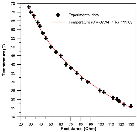
The hourly temperature of heated water was measured, using thermistor probes, at 7 point along the length and breadth of each heater as shown in the Fig (2). Two separate thermistors were used to measure the inlet and outlet temperatures of the storage water. In addition, the temperature of absorber plate measured by two additional thermistors and one to measure the glass temperature. Calibration of the thermistor was carried out by gradually varying the temperature and recording the corresponding resistance change. A bath of boiling water and a bowl of crushed ice were taken as the two limits of measurement. Calibration of thermistor was carried out against a standard mercury thermometer Data obtained regarding the temperature variation and the corresponding resistances are shown in Fig. (3).
Davis Vantage Pro with weather station package used to collect weather data. The standard version of the weather station package contains a rain collector, temperature sensor, humidity sensor, solar radiation sensor, ultra-violet (UV) sensor and anemometer. Temperature and humidity sensors were mounted in a passive radiation shield to minimize the impact of solar radiation on sensor readings. In our study, solar radiation and wind speed data are gotten from this station.
Fig (1). Three types of storage solar collector .
Fig (2). Positions of thermostat inside the storage solar collector
Fig (3). The calibration curve of the thermistors.
3. The Experimental Procedure
The collectors were tested under steady state conditions in which the solar intensity, wind speed, and the ambient temperature were considered constant for a period of time. Also, the inlet and outlet temperature difference and hence the useful energy delivered do not change appreciably during such a period [1]. At the onset of each experiment the collector was filled with fresh water, the glass cover was cleaned thoroughly, thermistors were checked, and the system faced south. The measuring instruments were switched on. Each test starts at sunrise and ends at sunset for
20 30 40 50 60 70 80 90 100 110 120 130
Resistance (Ohm)
10 15 20 25 30 35 40 45 50 55 60 65 70 75
T
e
m
p
e
ra
tu
re
(
C
)
Experimental data
the day of experimentation. The data recorded at the end of each hour included the various temperatures storage, glass cover, absorber plate and the tank inlet and outlet as well as the flow rate of the withdrawn hot water during the test run for each load pattern. The test run was repeated with and without for each load pattern. Some experiments were carried out with a load condition.
The load was connected to the storage collector in such a way that the cold inlet water entered at the bottom of collector and the hot water outlet was taken from the top of collector. A valve at the inlet of the collector regulated the mass flow rate of load water. The load mass flow rate was measured by timing the water collected in a graduated vessel of 1 liters capacity. The temperature of the inlet and outlet of the load water were record at the same time as the other data. A few experiments were conducted by imposing a large load in a short period. Load water, which 12-liter was withdrawn quickly from the collector at a period of approximately 5 minutes. In this, the average temperature of water withdrawn from the collector and the temperature of mains water entering the collector were record.
A few experiments were conducted by imposing a load on the system. In this case, the average temperature of water withdrawn from the tank and the temperature of mains water entering the tank were recorded in addition to the other measurements. A few experiments were conducted by imposing a load on the system. In this case, the average temperature of water withdrawn from the tank and the temperature of mains water entering the tank were recorded in addition to the other measurements.
4. Mathematical Model
A lumped parameter thermal balance on a storage solar collector, which is irradiated on one surface by solar energy as:
(Rate of heat absorber by surface absorber) + (rate of heat carried by water inter the collector) = (rate of heat absorbed by water) + (rate of heat absorber by metal of tank) + (rate of heat carried by water leaving the collector) + (heat lost from the collector).
Mathematically,
( )
( )
T g p Sh d a fw W wi
w C
w W c C
fw W wo L a p a
I τ α e F F A m C T
dT dT
m C m C
dt dt
m C T U A T T
× × × + × × = × × + × × + × × + × − ɺ ɺ (1)
We can re-write eq. (1) using the finite difference method as below:
( )
( )
T g p Sh d a fw W wi
w C
w w c C
fw W wo L a p a
I τ α e F F A m C T
T T
m C m C
t t
m C T U A T T
∆ ∆ ∆ ∆ × × × + × × = × × + × × + × × + × − ɺ ɺ (2)
In other form:
( ) ( )
( ) 1 /
( ) 1 / ( )
T g p sh d a fw w wo wi
w w swf swi
c C CF Ci L a p
I τ α e F F A J m C T T
m C T T τ
m C T T τ U A T Ta ∆ ∆ × × × = = × − + × − × + × − × + × − ɺ (3)
By simplify the eq.(3) we find the outlet temperature of load water from collector as :
( ) . . . . ( ) ( ) . . . w
wo wi swf swi
fw w fw
c c L a
CF Ci p a
fw w fw w
m J
T T T T
m C m τ
m C U A
T T T T
m C τ m C
∆ ∆ = + − − − − − − ɺ ɺ ɺ ɺ (4)
A program using Fortran-90 depending on eq. (4) using to find the Outlet temperature of load water from collector.
For no load condition we can used the following equation to estimate the temperature of water inside tank[1]:
( )
( ) ( )
( )
a L e
A U t
g p e t g p e t MC
w a w a
L L
τ α I τ α I
T T T T e
U U − + = + − − −
(5)
Eq.(5) was solved by trial and error method using a simple program achieved for this purpose.
5. Performance of the Collector
The maximum useful efficiency (MUE) was used in the paper to determine the efficiency of storage solar collector. Specifically [14],
( )
E L a
E o
F U T T µ KF η
I −
= − (6)
In eq. (1), T is the temperature of water in the storage, Ta
is the ambient temperature and I is the irradiance on the aperture plane of the collector.
η
o is the optical efficiency and UL the heat loss coefficient of the collector storage unit.K is the incidence angle modifier and FE is an enthalpy
retrieval defined as:
W W E
W W C C
M C F
M C M C =
+ (7)
Where MW and CW are, respectively, the mass and the
heat capacity of the water and MC and
C
C are therespective mass and heat capacity of the material from which the collector-storage unit is fabricated. Most important of all, the bars indicate time average over the daily heating period, from sunrise until the time the water reaches its maximum daily temperature typically about 8 h. That is to say, we use daily average, rather than instantaneous, values of the variables in Eq. (1). The bar over K indicates a daily energy average, which is fairly constant on a monthly basis. MUE is defined as:
max
( )
( )
W W sunrise
a
M C T T
µ
A I t dt
− =
where Aa is the collector aperture area, and the integral is
taken over the time from sunrise until the water reaches its maximum temperature.
6. Results and Discussions
The main purpose of a storage solar collector is the conversion of solar energy into thermal energy, many parameters was studied as below:
6.1. Parametric Storage Temperatures
The mean storage temperature is an important parameter. It is defined as a mass weighted average temperature, which is calculated as:
total n
i
i i
av
M
T
M
T
∑
==
1*
(9)
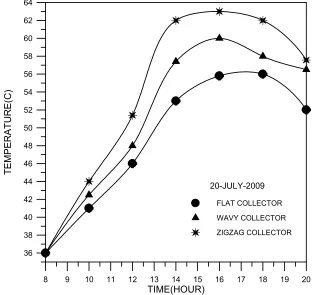
Fig. (4) shows the variation of mean storage temperature during a typical clear summer day. It is observed that the mean storage temperature increased with time, the mean
storage temperature reaches its maximum value and then decreases after 4 p.m. This is because the net energy absorbed becomes just lower than the heat losses, which means that the useful energy transferred to the water is insufficient to cause any further increase in the mean storage temperature.
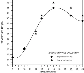
The maximum temperature was recorded for the zigzag storage collector with a front area of 1.414 m2. The minimum temperature recorded for the flat storage collector with the front area of 1 m2. The maximum value of mean storage temperature was 63 oC for this particular day in the zigzag storage collector. The maximum value of the mean storage temperature of the collector and the time of its occurrence is different for the autumn days as can be observed experimentally from Fig. 5. The maximum value depends on the solar radiation intensity, the prevailing weather conditions, the starting inlet temperature and the heat losses, which are different during the days. The maximum value was 45 oC for this particular autumn day, occurred at 3 p.m., and then decreased in the late afternoon.
The agreement between the numerical predictions and the experimental data is good as shown in fig. (6).
Fig (4). The variation of mean storage temperature summer day.
8 9 10 11 12 13 14 15 16 17 18 19 20 TIME(HOUR)
36 38 40 42 44 46 48 50 52 54 56 58 60 62 64
T
E
M
P
E
R
A
T
U
R
E
(C
)
20-JULY-2009
FLAT COLLECTOR
WAVY COLLECTOR
Fig (5). The variation of mean storage temperature of the zigzag collector through the autumn and summer seasons.
Fig(6). The variation of mean storage temperature of the zigzag collector in autumn day.
7. Effect of Loading
In order to show the effect of loading conditions on the system performance, some experiments were carried out with hot water withdrawal from the collector during the operating period in October and July 2009. The hot water withdrawn was taking continuously and intermittently. This was done by permitting cold mains water to enter the collector at its bottom, and the hot water was withdrawn from the top of the collector. The mass flow rate and temperature of the water
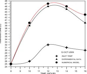
were both measured. Fig.(7) show the variation of system temperatures for a clear day with continuous load condition. The mass flow rate was 0.2 liter/min where the total hot water removed during the whole working period was 96 and 168 liters in winter and summer seasons respectively. Fig. (7) shows the variation of inlet, outlet and mean storage temperature during autumn day. It is observed that the outlet temperatures are increasing throughout the period between 8 a.m. and 1 p.m., which indicates that the useful energy (qu) is
higher than that carried out by the load water. After 1 p.m., these temperatures start decreasing because the value of
8 9 10 11 12 13 14 15 16 17 18 19 20
TIME (HOUR)
22 24 26 28 30 32 34 36 38 40 42 44 46
T
E
M
P
E
R
A
T
U
R
E
(
C
)
ZIGZAG STORAGE COLLECTOR
AUTUMN DAY
useful energy becomes lower than the energy carried out by the load water. The numerical data showed a higher value than experimental result but the agreement between the numerical and experimental data is acceptable as shown in Fig. (8).
Fig. (9) shows the variation of system temperature for a clear day with intermittent load conditions on a autumn day. This load condition was imposed by withdrawing hot water
from the storage at the end of each hour. The amount of water withdrawal was 10.5 liter/hour, starting at 6 a.m. and ending at 6 p.m. The total hot water withdrawal during the day would be 126 liters. Temperature behavior is similar to the continuous load conditions of Fig. 6. The temperature difference between the outlet and inlet temperature is higher than the continuous load conditions, and the zigzag collector have the greatest difference between the other designs.
Fig (7). Variation of system temperatures of storage collector with continuous load in autumn day.
Fig (8). Comparison of experimental and numerical outlet temperature of triangular collector with continuous load.
8 9 10 11 12 13 14 15 16
TIME (HOUR) 24
25 26 27 28 29 30 31 32 33 34 35 36 37 38 39 40 41 42 43 44 45 46 47 48
T
E
M
P
E
R
A
T
U
R
E
(
C
)
12-OCT-2009
Fig (9). Variation of system temperatures of storage collector with intermittent load in autumn day
Fig (10). MUE graph for the zigzag storage collector under study.
8. Efficiency of Storage Collector
From the result of the previous section, the zigzag storage collector was the best to obtain a high temperature than the other two designs. The daily value of MUE of this type are, then plotted against
I T
Tavg − amb
as shown in fig.(10), the equation of this curve as below:
0.673 9.8147( av amb) T
T T MUE
I −
= − (10)
In comparison eq.(10) with eq.(6), we find that
8147 . 9 − =
−FEUL , the value of
F
E can be calculated fromeq. (7) and equal to 0.96, that mean the heat transfer losses coefficient
U
Lequal to 10.22 W/m2.K, this value is high and to enhancement the performance the collector, reduction of this value is very necessary.0.006 0.008 0.010 0.012 0.014 0.016 0.018 0.020 0.022 0.024 0.026
(Taverage - Tamb)/I
0.425 0.450 0.475 0.500 0.525 0.550 0.575 0.600 0.625
M
U
E
9. Conclusions and Recommendations
1. The performance of the zigzag flat plate collector was best than the wavy and flat plate collector.
2. The maximum value of temperature difference across the zigzag collector with 80 liters storage was 27 oC in summer and 20 oC in autumn during clear sky and no load conditions. With continuous loading test for zigzag flat plate collector the maximum temperature difference between the outlet and inlet temperature is 14 oC at 12 p.m. and 10 oC at the end of the day.
3. Studying water motion inside the collector experimentally by using the heliography techniques.
4. Experimental analysis of performance for parallel, series, and parallel-series connection of a bank of storage collectors.
Notation
Symbol Description Units
a
A Irradiated face of collector m2 CW Specific heat of water J/kg.oC
c
C Specific heat of metal of tank J/kg.oC
d
F Fouling factor -
sh
F Shading factor - h Convection heat transfer coefficient W/m2.oC
T
I Total solar radiation on a tilted
surface W/m
2
c
m Mass of the empty collector kg
fw
mɺ Mass flow rate of water kg/s
w
m Mass of water inside the collector kg
a
T Temperature of the ambient air oC
P
T Temperature of the absorber plate oC
wo
T Outlet temperature of load water from
collector
o
C
wi
T Inlet temperature of load water from
collector
o
C
cf
T
Final temperature of the metal of tank oCci
T Initial temperature of the metal of
tank
o
C UL Collector over all coefficient W/m2.K
wsf
T Final temperature of the water inside
tank
o
C
wsi
T Initial temperature of the water inside
tank
o
C
sunrise
T
Temperature of water inside tank atthe sunrise time
o
C UL Collector over all coefficient W/m2.K
c
η Collector efficiency -
τα
Transmittance – absorbtance product -τ
∆ Change in the period time sec
References
[1] Duffie, J. and Beckman, W., 1991, Solar energy thermal processes, John Wiley and Sons, New York.
[2] Garge, H.P and Rani, U., 1982, Theoretical and experimental studies on collector/storage type solar water heater, Solar energy, Vol.29, pp.467-478.
[3] Vaxman, M. and Sokolov, M., 1985, Experiments with an integral compact solar water heater, Solar energy, Vol. 34, No. 6, pp. 447-454.
[4] Muneer, T., 1985, Effect of design parameters on performance of built-in storage solar water heater; Energy conservation and Management Vol. 25, No. 3, pp. 277-281.
[5] Khadiar ,M, 1987, Solar storage by using a bed of rock, M.Sc thesis, Mechanical engineering department, University of Basra.
[6] Mohamed, A.A.,1997, Integrated solar 'collector-storage tank system with thermal diode; Solar Energy, Vol. 61, pp. 221-218.
[7] Farhan, .A, 2002, Computational model for a prism shaped storage solar collector with a right triangular cross section, M.Sc thesis, Mechanical engineering department, University of Baghdad.
[8] Alawi, W.H, 2004, Numerical and experimental study of the solar collector storage pyramidical with right angle, M.Sc. Thesis, University of Technology, Baghdad.
[9] Junaidi HA, Henderson D, Muneer T, Grassie T, Currie J,2002, Study of stratification in a (ICSSWH) integrated collector storage solar water heater, Ninth AIAA/ASME Joint Thermophysics and Heat Transfer Conference, San Francisco, California.
[10] Jose´ M.S. Cruz, Geoffrey P. Hammond, Albino J.P.S. Reis,2002, Thermal performance of a trapezoidal-shaped solar collector/energy store, Applied Energy; 73 pp.195–212.
[11] Buchberg, H., Catton, I., and Edwards, D.K., 1976, Natural convection in enclosed spaces- A review of application of solar collection, Trans of the ASME, J. of Heat transfer, Vol. 98, pp. 182-188.
[12] Test, F.L., 1976, Parametric study of flat-plate solar collectors, J. of Energy conversion, Vol. 16, pp.23-33.
[13] Whillier, A, 1977, Prediction of performance of solar collector, ASHREA GRP 170, Application of solar energy for heating and cooling of building, Edited by Jordon, R.C. and Liu, B.Y.H., ASHREA.