Effect of Rake Angles on Tool during
Orthogonal Metal Cutting Process for
Different Materials through Ansys
Ritesh Patidar¹, Dr. Suman Sharma²
1. M. E Production Engineering and Engineering Design, Department of Mechanical Engineering Sagar Institute of Research & Technology, Indore, India
2. Professor and Head of Mechanical Department Sagar Institute of Research & Technology, Indore, India
Abstract— the process of orthogonal metal cutting is
analyzed using the Academic FEA package ANSYS/Explicit 14.5. The focus of the results presented in this paper, effect on tool by different rake angles and depth of cuts in orthogonal metal cutting process. A number of finite element simulations have been done with the ANSYS/Explicit Dynamics 14.5 to initiate the stress variations on tool during orthogonal metal cutting process. A tool rake angle varying from 20ᵒ, 25°, 30ᵒ and a friction coefficient is constant 0.4 mm and constant cutting speed 2.54 m/s with depths of cut are 0.05, 0.1, 0.15 mm has been considered in the simulations. The results of these simulations provide insight how stresses are influenced by rake angle and depth of cuts.
Keywords: —ANSYS, explicit dynamics, FEA, Materials, Tool
life.
I. INTRODUCTION
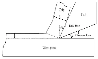
Two types of metal cutting used in industries orthogonal cutting and oblique cutting. In orthogonal cutting, the cutting edge of the tool is at right angles to the direction of the relative motion between the tool and the work piece. In oblique cutting, the cutting edge is inclined but not perpendicular to the direction of the relative motion between the tool and work piece. During the cutting process several forces acting on the tool. The study of effect of these forces is necessary for the qualitative analysis. The cutting parameters include the cutting speed, feed and depth of cut.
Fig. 1:The classical orthogonal cutting model
Machinability is partial by the tool variables, machine variables, cutting conditions and work material variables. These parameters may create failure of tool, poor surface finish, impulsive increase in forces, increase in temperature and stresses. The tool life and tool wear also depends on these
parameters. For the optimum machining, these parameters should be in proper consideration like nature of cut to be made, feed, depth of cut, speed.
II LITERATURE REVIEW
F. W Taylor (1907) [1] showed that an optimum or economic cutting speed exists which could maximize material removal rate. Manufacturing industries have long depended on the skill and experience of shop-floor machine-tool operators for optimal selection of cutting conditions and cutting tools. Considerable efforts are still in progress on the use of hand book based conservative cutting conditions and cutting tool selection at the process planning level. The most adverse effect of such a not-very scientific practice is decreased productivity due to sub-optimal use of machining capability.
Jossel (1865) [2] forces were obtained in lathe cutting and drilling by measuring the torque required to turn the machine while cutting, care being taken to subtract the torque required to overcome the friction of the machine. The effects of uncut chip thickness, speed and rake angle were studied. References to “cutting fluids” are also found in his work (linseed oil, quicklime and nitric acid to name a few), although no explanation of their benefit was attempted.
Tresca (1878) [3] time was the first to correctly model the process ahead of the tool as one of shear, although he may be criticized for his viewpoint that the chip formation took place by fracturing of the metal on successive shear planes rather than by plasticdeformation. This is understandable though since the plastic deformation of metals in operations other than cutting was only beginning to be investigated at the time.
Dr. Merchant’s (1944) [5] presented a simplified 2-D model of the conventional oblique machining process called the orthogonal machining process which considers only two axes at a time which is also one of the widely used research model as it involves less complicated computations, easier to analyze and moreover is found to be in good agreement when extended to a 3-D model. Merchant’s orthogonal machining model is of two types 1) orthogonal plate turning at moderate and high speeds (OPT), 2) orthogonal tube turning at moderate speeds (OTT)
II. SIMULATION PARAMETERS
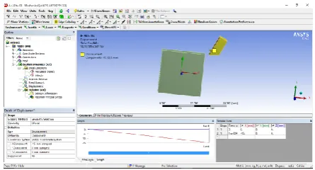
The purpose of this section is to discuss the modeling options in the Academic FEA software ANSYS/Explicit 14.5. A schematic diagram of the model problem in 2D is given below.
Fig. 2: Schematic diagram of orthogonal metal cutting process
The material used is AISI 4340 steel with a Young’s Modulus
(E) of 207 GPa and density (ρ) of 7800 kg/m3
.The chip layer has a height of 50 μm, 100 μm and 150 μm for the various
depth of cuts. The rest of the work piece has a length of 2540
μm and a height of 889 μm. The tool in this study is of a parallelogram shape and has a base length of 407 μm and a height of 762 μm. The tool material properties are taken as E
=207 GPa and ρ = 7800 kg/m3
. The boundary conditions for the chip-work piece-tool system are given as follows. The upper boundary of the tool moves incrementally towards the left with a constant speed of 2.54 m/s (152.4 m/min) while it is restrained vertically. The left end and right end of the work piece are restrained in the cutting direction but not vertically. Since the bottom boundary of the work piece is expected to undergo very little deformation during cutting, it is assigned zero displacements in both directions. A contact pair between the chip and tool face is defined (as shown in Fig 2.) in ANSYS/Explicit 14.5 to take care of the chip sliding on the tool face during the machining.
III 3D MODELING
The tool material is considered is AISI 4340 steel molded with CATIA V5.
In this project the model dimensions is following. The chip layer has height of 50 µm. 100 μm and 150 μm for the various depths of cuts. The rest of the work piece has a length of 2540 μm and a height of 889 μm. The tool in this study is of a parallelogram shape and has a base length of 407 μm and a height of 762 μm. The tool material properties are taken as E =207 GPa and ρ = 7800 kg/m3. The tool material properties are taken as E =207 GPa and ρ = 7800 kg/m3. Three different rack angles 20°, 25° and 30° are used and nose radius is 0.2mm.
Fig. 4: (a) 20° rack angle, (b) 25° rack angle. (c) 30° rack angle
VARIATION IN MACJINING PARAMETERS
Table 1: Variation in Machining Parameters
IV FEA MODELING
Table 2: Tool material properties
Material Density Elastic
modulus
Poisson’s Ratio
AISI 4340 7800
kg/m3
207 GPa 0.3
Meshing of orthogonal machining model
Meshing is an important thing in finite element analysis. We have use 0.9 mm element size and we got 4494 nodes and 3474 element.
Fig.5:4 meshing of orthogonal machining model
Boundary conditions for orthogonal machining model Initial conditions for tool
V= -2540m/s
Fig.6: Velocity for orthogonal machining model (tool)
Fig.7: Fixed support for orthogonal machining model (work piece)
Fig.8: displacement for orthogonal machining model (tool)
V RESULT AND ANALYTICAL DISCUSSION
In this project three different material of steel in orthogonal machining process analysis. Different rack Angles and depth of cuts modeled for FEA work 20°, 25°and 30° rack angles and 0.05, 0.1 and 0.15 depths of cuts.
Reference results of AISI 4340 steel are
Table 3: Reference results of AISI 4340 steel
Rack angle
Depth of cut (t)
mm
Cutting speed (v)
m/s
Coefficient of friction
(µ)
Stress (MPa)
20° 0.05 2.54 0.4 1421
20° 0.1 2.54 0.4 1381
20° 0.15 2.54 0.4 1376
25° 0.05 2.54 0.4 1416
25° 0.1 2.54 0.4 1416
25° 0.15 2.54 0.4 1341
30° 0.05 2.54 0.4 1715
30° 0.1 2.54 0.4 1387
30° 0.15 2.54 0.4 1416
Dynamic analysis results from ANSYS 14.5 of AISI 4340 steel
Table 4: Dynamic analysis results from ANSYS 14.5 of AISI 4340 steel
Rack angle
Depth of cut (t) mm
Cutting speed (v) m/s
Coefficient of friction (µ)
Stress (MPa)
20° 0.05 2.54 0.4 1426
20° 0.1 2.54 0.4 1356
20° 0.15 2.54 0.4 1320
25° 0.05 2.54 0.4 1462
25° 0.1 2.54 0.4 1403
25° 0.15 2.54 0.4 1374
30° 0.05 2.54 0.4 1800
30° 0.1 2.54 0.4 1268
ANSYS results of AISI 4340 steel
Fig. 9: ANSYS results of AISI 4340 steel
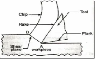
The von-Misses stress distributions in Fig 10 help us to observe the plastic flow behavior. Upon close observation it can be seen that the stress contours are parallel to the tool chip ahead of the tool tip and aligned slightly towards the left in a forward direction. The peak contour is seen to connect the tool tip and the turning point on the chip's free boundary, forming the ``shear'' angle (Shet and Deng) [1].
Analytically solution for 20° rack angle and 0.05 depth of cut
Given data
Force, F = 205 N
Stress F σ = AB * w
Where
W= ρ * L*b*t
W= 7800*0.762*0.5*0.407 W= 1.209 Kg
To find area
Fig. 10: Shear plane angle
Then AB = 0.1196
Stress
Variation of cutting force with varying rake angles and depth of cut
Fig. 11: Stresses at 20ᵒ rake angle
Fig. 12: Stresses at 25ᵒ rake angle
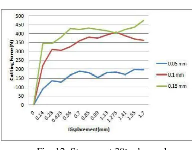
Fig. 12: Stresses at 30ᵒ rake angle
Following figure shows the variation of horizontal cutting forces with the tool tip displacement for varying rake angles and depth of cut. For each value of depth of cut, the cutting force is seen to increase with increase tool tip displacement. For each rake angle, the cutting force for a particular depth of cut is seen to decrease with tool tip displacement.
VI. CONCLUSION
parameters like rake angle and depth of cut and for various materials so as to optimize the machining process for that particular material.
REFERENCES
[1] 1907. "On the Art of Cutting Metals," Transactions of the American Society of Mechanical Engineers, Vol. XXVIII, 1907, pp. 31–350. [2] Merchant, M.E., “Mechanics of the Metal Cutting Process,” Journal of
Applied Physics, Vol. 16, pp 267 -275, 1945.
[3] Komanduri, R., Raff, L.M., “A review of the molecular dynamics simulation of machining at the atomic scale”, Proc. Instn. Mech. Engrs., Vol. 215 Part B, pp 1639 -1672, 2001.
[4] Payton, Lewis, N., “A Basic Correction to the Orthogonal Metal Cutting Models”, Proceedings of the ASME 2009 International Manufacturing Science and Engineering Conference, MSEC2009.
[5] Carroll, John, T (III)., and Strenkowski, John, S., “Finite Element Models of Orthogonal Cutting with Application of Single Point Diamond Turning”, Int. J. MechSci, Vol 30, No 12, pp 899 -920, 1988.
[6] Shih, Albert, J, M., Chandrasekar, S., and Yang, Henry, T, Y., “Finite element Simulation of Metal Cutting Process with Strain- Rate and Temperature Effects”, Fundamental Issues in Machining, ASEM PED – Vol 43, pp 11, 1990.
[7] Komvopoulos, K., and Erpenbeck, S, A., “Finite Element Modeling of Orthogonal Metal Cutting”, Journal of Engineering for Industry, Vol, 113 pp 253 – 267, 1991.
[8] Zhang, Bingqi., and Bagchi, Amit., “Finite Element Simulation of Chip Formation and Comparison with Machining Experiment”, Computational Methods in Materials Processing, MD- Vol. 39/PED Vol. 61, ASME 1992.
[9] Marusich, T, D., and Ortiz, M., “A Parametric Finite Element Study of Orthogonal High-Speed Machining”, Internat.J. Num. Methods Engrg. , 1995.
[10] Haung, J, M., and Black, J.T., “An Evaluation of Chip Formation Criteria for the FEM Simulation of Machining”, Journal of Manufacturing Science and Engineering, Vol. 118, pp 545-554, 1996.
[11] Marusich, Troy, D., “Effects of Friction and Cutting Speed on Cutting Force”, Proceedings of ASME Congress, 2001.
[12] Arrazola, P, J., Ugarte, D., Montoya, J., Villar, A., and Marya, S., “Finite Element Modeling of Chip Formation Process with ABAQUS/EPLICIT 6.3”, VIII International Conference on Computational Plasticity, 2005.
[13] Pramanik, A., Zhang, L, C., and Arsecularatne, J, A., “An FEM investigation into the behavior of metal matrix composites: Tool-particle interaction during orthogonal cutting”, International Journal of Machine Tools and Manufacture 47, pp 1497-1506, 2007.
[14] Masillamani, David, P., and Chessa, Jack., “Determination of Optimal Cutting Conditions in Orthogonal metal Cutting Using LS-DYNA with Design of Experiments Approach”, 8th International LS-DYNA Users Conference, May 2004, Dearborn, MI, USA.
14. Raczy, A., Altenhof, W,J., and Alps, A, T., “An Eulerian Finite Element Model of the Metal Cutting Process”, 8th International LS-DYNA Users Conference, May 2004, Dearborn, MI, USA.
[15] Villumsen, Morten, F., and Fauerholdt, Torben, G., “Prediction of Cutting Forces in Metal Cutting, Using the Finite Element Method, a Lagrangian Approach”, LS-DYNA Anwenderforum, Bamberg, 2008.
[16] Su, Chong., Hou, Jun-Ming., Zhu, Li-da., and Wang, Wan-shan., “Finite Element Analysis of Two Dimensional metal Cutting process”, The 3rd International Conference in innovative Computing Information and Control. IEEE 2008.
[17] Yuming, Zhu., and Guicheng, Wang., “Simulation Model and Mechanism of Burr Formation”, International Workshop on Modeling, Simulation and Optimization, IEEE 2008.
[18] Oxley, P.L.B., 1989, Mechanics of Machining, An Analytical Approach to Assessing Machinability. Halsted Press, John Wiley & Sons Limited, New York.
[19] Zerilli, F, J., and Armstrong, R, W., “Dislocation mechanics based constitutive relations for material dynamics calculations”, Journals of Applied Physics, Vol. 61/5, pp 1816-1825, 1987.
[20] Johnson G, R., and Cook, W, H., “A constitutive model and data for metals subjected to large strains, high strain rates and high temperatures”, Proceedings of the 7th International Symposium on Ballistics, The Hauge, The Netherlands, pp 541- 547, 1983.
[21] Lesuer, D, R., kay, G, J., and LeBlanc, M, M., “Modeling large –Strain, high-Rate Deformation in Metals”, Third Biennial Tri-Laboratory Engineering Conference Modelling and Simulation, CA USA, 1999.