Published online October 30, 2013 (http://www.sciencepublishinggroup.com/j/ijepe) doi: 10.11648/j.ijepe.20130205.12
Load frequency control of interconnected hydro-thermal
power system using conventional pi and fuzzy logic
controller
Muhammad Ahsan Zamee
1, Dipankar Mitra
2, Sadaf Yusuf Tahhan
21Department of Electrical & Electronic Engineering, World University of Bangladesh, Dhaka, Bangladesh
2Department of Electrical & Electronic Engineering, Chittagong University of Engineering and Technology, Chittagong, Bangladesh
Email address:
[email protected] (M. A. Zamee), [email protected] (D. Mitra), [email protected] (S. Y. Tahhan).
To cite this article:
Muhammad Ahsan Zamee, Dipankar Mitra, Sadaf Yusuf Tahhan. Load Frequency Control of Interconnected Hydro-Thermal Power System Using Conventional PI and Fuzzy Logic Controller.International Journal of Energy and Power Engineering.
Vol. 2, No. 5, 2013, pp. 191-196. doi: 10.11648/j.ijepe.20130205.12
Abstract:
In industry or any area increasing load is a vast problem for power generation plants due to increase in demand for power. So making balance between generation and demand is the operating principle of load frequency control (LFC). The reliable operation of a large interconnected power system necessarily requires an Automatic Generation Control (AGC). The objective of AGC is to regulate the power output of Generators within a specified area in response to change in the system frequency, tie line power or relation of the two to each other, so as to maintain the scheduled system frequency and power interchange in the other are within the prescribed limits. This paper presents the use of conventional PI controller and artificial intelligence to study the load frequency control of interconnected power system. In the proposed scheme, a control methodology is developed using conventional PI controller and Fuzzy Logic controller (FLC) for interconnected hydro-thermal power system. The control strategies guarantees that the steady state error of frequencies and inadvertent interchange of tie-lines power are maintained in a given tolerance limitations. The performances of the controllers are simulated using MATLAB/SIMULINK package. A comparison of Fuzzy controller and PI controller based approaches shows the superiority of proposed Fuzzy logic controller for step change in loading conditions. The simulation results also tabulated as a comparative performance in view of settling time and peak over shoot.Keywords:
Load Frequency Control, Fuzzy Logic Controller, PI controller, MATLAB/SIMULINK1. Introduction
Due to increase in system load; turbine speed drops before the governor can adjust the input. As the change in the value of speed decreases, the error signal becomes smaller and the positions of governor valve get close to the required position, to maintain the constant speed. However the constant speed will not be the set point and there will be an offset, to overcome this problem an integrator is added, which will automatically adjust thegeneration to restorethe frequency to its nominal value. This scheme is called automatic generation control (AGC). The role of AGC is to divide the loads among the system, station and generator to achieve maximum economy and accurate control of the scheduled interchanges of tie-line power while maintaining a reasonability uniform frequency. Automatic generation control (AGC) plays a very important role in power system
would accomplish the desired objective. This control signal is known as area control error (ACE).ACE serves to indicate when total generation must be raised or lowered in a control area. In an interconnection, there are many control areas, each of which performs its AGC with the objective of maintaining the magnitude of ACE (area Control Error) “sufficiently close to 0” using various criteria. In order to maintain the frequency sufficiently close to its synchronous value over the entire interconnection, the coordination of the control areas’ actions is required. Any wide deviation from the nominal value of frequency or voltage will lead the system to total collapse. Hence AGC has gained importance with the growth of interconnected systems and with rise in size of interconnected system automation of the control system have aroused. A number of control strategies exist to achieve better performance. [7]
The most applied controller is Conventional Proportional Integral (PI) [3, 6]. It is easier but usually gives large settling time. Most research going on now is based on artificial intelligent systems (fuzzy and neural networks). The inherent gain of these techniques is that they do not require the system model and identification but depend on human expertise knowledge of the behavior.
In this paper, a fuzzy logic controller along with PI controller is proposed and performance comparison is carried out for conventional PI.
2. Load Frequency Control Theory
2.1. The Investigated Power System
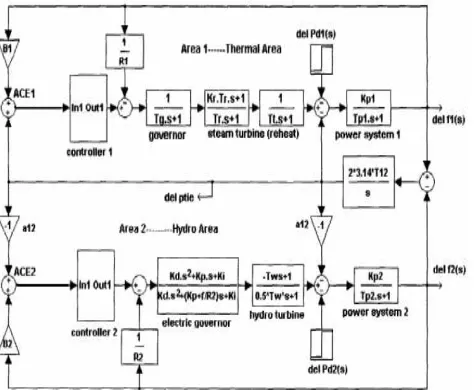
The detailed block diagram modeling of two area thermal-hydro power system for load frequency control investigated is shown in figure 1. An extended power system can be divided into a number of load frequency control areas interconnected by means of tie lines. Without loss of generality one can consider a two- area case connected by single tie line (Surya-Prakash et al.2009).
Fig. 1: Block diagram model of hydro-thermal reheat power system.
The control objectives are as follows:
● Each control area as for as possible should supply its own load demand and power transfer through tie line should be on mutual agreement.
● Both control areas should controllable to the frequency control.
In an isolated control area case the incremental power (∆PG − ∆PD) was accounted for by the rate of increase of stored kinetic energy and increase in area load caused by increase in frequency. Since a tie line transports power in or out of an area, this fact must be accounted for in the incremental power balance equation of each area.
2.2. Modeling of the Tie-Line
The power transfer equation through tie line is given by,
)
(
1 22 1
12
=
Sin
δ
−
δ
x
V
V
P
(1)12
P
= Power transferred from area 1 to 2 through tie line. Considering area 1 has surplus power and transfers to area 2.)
(
1 212 2 1
12
=
Sin
δ
−
δ
X
V
V
P
(2)Therefore, Power transferred from Area 1 to Area 2 is given by the following equation
(
(
)
(
)
)
2
)
(
1 20
12
f
s
f
s
s
T
s
P
=
∆
−
∆
∆
π
(3)T0 = Torque produced
2.3. Tie line Control
In normal operation the power on the tie-line follows from the equation
i.e.
1
1 1 12 1
0 1 1 2 [ ( ) ( ) ( )] ( ) ( ) T E H
P s P s P s s f s
f B f s
∆ − ∆ − ∆ = ∆ + ∆ (4) 1 1 1 0 1 1 1 0 1
2
1
( )
1
2
1
P
H
f s B
s
f
B
H B
If
f
K
=
∆
+
=
(5)Equation (4) can be written as
)]
(
)
(
)
(
)[
(
)
(
1 1 1 121
s
G
s
P
s
P
s
P
s
f
=
P∆
T−
∆
E−
∆
21 12 1 1 1
1
)
(
P
P
sT
K
s
G
P P P∆
=
∆
+
=
(7)Where ∆PEis real load change
Due to the action of turbine controllers, the generator increases its output by the amount ∆PT.
The net surplus power ∆PT− ∆PEwill be absorbed by the system.
Tie-line bias control is used to eliminate steady state error in frequency in tie-line power flow. This states that the each control area must contribute their share to frequency control in addition for taking care of their own net interchange.
Let
ACE1 = area control error of area 1 ACE2 = Area control error of area 2
In these control areas, ACE1 and ACE2 are made linear combination of frequency and tie line power error.
1 12 1 1
ACE = ∆ + ∆P b f (8)
2 21 2 2
ACE = ∆ + ∆P b f (9)
Where, the constant b1 & b2 are called area frequency bias of area 1 and area 2 respectively.
Now ∆PR1 and ∆PR2 are mode integral of ACE1 and ACE2 respectively.
dt
f
b
P
K
PR
ti
(
12 1 1)
0 1
1
=
−
∆
+
∆
∆
∫
(10)dt
f
b
P
K
PR
ti
(
21 2 2)
0 2
2
=
−
∆
+
∆
∆
∫
(11)Taking Laplace transform of the above equation, we get
)]
(
)
(
[
)
(
1 12 1 11
P
s
b
f
s
s
K
s
PR
=
−
i∆
+
∆
∆
(12))]
(
)
(
[
)
(
21 2 22
2
P
s
b
f
s
s
K
s
PR
=
−
i∆
+
∆
∆
(13)The step changes ∆PD1 and ∆PD2 are applied simultaneously in control area 1 and 2 respectively. When steady state conditions are reached, the output signals of all integrating blocks will be constant and their input signal must become zero.
i.e. ∆P12 + b1∆f1 = 0 (input of integrating block
s
K
i1−
) (14)∆P21 + b2∆f2 = 0 (input of integrating block
s
K
i2−
)(15)∆f1 – ∆f2 = 0 (input of integrating block
s
T
122
π
−
) (16)∆P12 = ∆Ptie, 1 and ∆P12 = ∆Ptie, 2 Therefore
=
−
=
−
=
∆
∆
12 21 12 2 , 1 ,1
a
T
T
P
P
tie tieConstant (17)
Hence ∆Ptie,1 = ∆Ptie, 2 = 0 ∆PR1 = ∆PR2
And ∆f1 = ∆f2 = 0
Thus, under steady condition change in the tie- line power and frequency of each area is zero. This has been achieved by integration of ACEs in the feedback loops of each area (Surya-Prakash et al. 2009). Control methodology used (FLC & PI) is mentioned in next preceding sections. [1, 2, 8]
3. Controller Used
a) Conventional PI Controller b) Fuzzy Logic Controller.
3.1. Conventional PI Controller
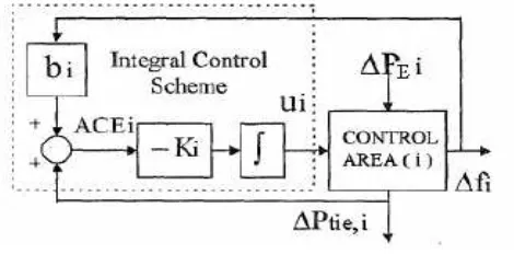
When an integral controller is added to each area of the uncontrolled plant in forward path the steady state error in the frequency becomes zero. The task of load frequency controller is to generate a control signal u that maintains system frequency and tie-line interchange power at predetermined values [2]. The block diagram of PI controller is shown in figure2.
Fig. 2: Conventional PI controller
Conventional Proportional plus Integral controller (PI) provides zero steady state frequency deviation, but it exhibits poor dynamic performance (such as number of oscillation and more settling time), especially in the presence of parameters variation and nonlinearity [10].In PI Controller Proportionality constant provides simplicity, reliability, directness etc. The disadvantage of offset in it is eliminated by integration but this system will have some oscillatory offset. The control signals can be written as:
U1 = K p. ACE1 – K i ʃ ACE dt
U2 = K p. ACE2 – K i ʃ ACE2 dt
respectively. For conventional PI controller, the gain K p and K i has been optimized using integral square error (ISE) criterion. For ISE technique, the objective function used is,
J=
F
P
dt
t
tie
∫
∆
+
∆
+
+
∆
0
2
1
)
F
(
Where
F = Change in frequency Ptie = Change in tie line power
3.2. Fuzzy Logic Controller
Fuzzy logic is a problem-solving control methodology incorporated in control system engineering, to control systems when inputs are either imprecise or the mathematical models are not present at all. There are three principal elements to a fuzzy logic controller
1.Fuzzification module (Fuzzifier) 2.Inference rule engine
3.Defuzzification module (Defuzzifier)
For Load Frequency Control the process operator is assumed to respond to respond to variables error (e) and change of error (ce) (that is frequency deviation and change in frequency deviation). five number of triangular membership function (MFs) which provides better dynamic response with the range on input (error in frequency deviation and change in frequency deviation) i.e. universe of discourse is -0.25 to 0.25. The numbers of rules are 25. The dynamic response are obtained and compared to those obtained with conventional integral controllers.
Fig. 3: Membership functions for control input variable
Table 1: Fuzzy Interference rule for fuzzy logic controller
Input e(k)
ce(k)
NB NM ZE PM PB
NB NB NB NM NM ZE
NM NB NB NM ZE ZE
ZE NM NM ZE PM PM
PM ZE PM PM PB PB
PB ZE ZE PM PB PB
4. Results and Discussions
MATLAB/SIMULINK software has been used for evaluating the performance of proposed controller for both
PI and Fuzzy Logic Controller. For fuzzy logic controller, fuzzy logic toolbox has been used to set up the membership function and interference rules.
Fig. 4: Setting up fuzzy rules in MATLAB/SIMULINK
Fig. 5: Frequency response without using any controller.
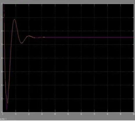
Fig. 7: Frequency response using fuzzy logic controller
4.1. Comparison of System Performance
Table 2: Performance evaluation without using any controller
Thermal Hydro Combined
Frequency deviation
-4 -1.5 ~ +2 -7.8
Settling time
Stable at deviated frequency
Stable at deviated frequency
Stable at deviated frequency
Table3: Performance evaluation using PI controller
Thermal Hydro Combined
Frequency deviation
-3.5~+3.5 -4.0~2.7 -6.5~+2.5
Settling time 40 Sec 45 sec 50 Sec
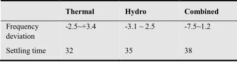
Table 4: Performance evaluation using Fuzzy Logic controller
Thermal Hydro Combined
Frequency deviation
-2.5~+3.4 -3.1 ~ 2.5 -7.5~1.2
Settling time 32 35 38
5. Conclusion
From the above research it can be seen concluded that the transient response, settling time and peak overshoot in case of fuzzy logic controller is lesser compared to the conventional PI controller. Thus simulation results of FLC have better control performance over conventional PI when some disturbance in load is given to the system. In short we can say that FLC is adequate for better quality and reliable electric power supply.
6. Future Scope
1.More than two areas such as thermal, hydro, gas etc can be interconnected and controlled for automatic generation of controlled power.
2.New controllers can be designed with others Artificial Intelligence algorithms for better control performance in terms of frequency and tie line power deviation. 3.More than one controller can be used such as
conventional PI, PID and FLC or Artificial Neural Network in serial or parallel for reducing transient response and peak overshoot.
Appendix
Parameters are as follows:
f = 50 Hz, R1 =R2= 2.4 Hz/ per unit MW, Tg = 0.08 sec, Tp=20 sec
P tie, max = 200 MW Tr = 10 sec kr = 0.5,
H1 =H2 = 5 sec Pr1 = Pr2 =2000MW Tt = 0.3 sec Kp1=Kp2 = 120 Hz.p.u/MW Kd =4.0 ki = 5.0 Tw = 1.0 sec
D1 =D2= 8.33 * 10-3 p.u MW/Hz.
Nomenclature
F : Nominal system frequency
Pri : Area rated power, Hi: Inertia constant ∆ P Di : Incremental load change
∆ Pg i : Incremental generation change
T12 : Synchronizing coefficient, Tg:Steam governor time constant
Kr : Reheat constant, Tr : Reheat time constant
Tt : Steam turbine time constant
Ri : Governor speed regulation parameter Bi: Frequency bias constant
References
[1] Anand B., Ebenezer A. Jeyakumar. 2009. Load frequency control with fuzzy logic controller considering non-linearities and boiler dynamics, ICGST-ACSE Journal, ISSN 1687-4811, Volume 8, issue 111, pp 15-20.
[2] Aravindan P., Sanavullah M.Y. 2009. Fuzzy Logic Based Automatic Load Frequency Control of Two Area Power System With GRC, International Journal of Computational Intelligence Research, Volume 5, Number 1. pp. 37–44. [3] Jawat, T. and Fadel, A, B. “Adaptive Fuzzy Gain Scheduling
for Load frequency control”, IEEE Trans. on PAS, vol. 14, No 1, February 1999.
[4] Ibraheem, Kumar P., Kothari D.P., 2005. Recent Philosophies of Automatic Generation Control strategies in Power systems,
IEEE Transaction on Power System Vol.20, No.1, pp-346-357.
[5] Surya-Prakash, Sinha S.K., Brijesh-Singh, Pandey A.S. 2009. Impact of slider gain on Load Frequency Control using Fuzzy Logic Controller, ARPN Journal of Engineering and Applied Science, Vol. 4, No 7.pp. 20-27.
conf; vol. 57, No. 2, 1995, pp 1419-1427.
[7] Amit Kumar, Aziz Ahmad, Ashwani Grover, Umesh Gupta, “Load Frequency Control Using Fuzzy Logic” , International Journal of Scientific and Research Publications, Volume 2, Issue 7, July 2012
[8] Surya Prakash , S. K. Sinha, “Application of artificial intelligence in load frequency control of interconnected power system”, International Journal of Engineering, Science and Technology.
[9] A. Mangla and J. Nanda , “Automatic Generation Control of an Interconnected Hydro-Thermal System Using Conventional Integral and Fuzzy Logic controller”, International conference on electrical utility, deregulation, destructuring, and power technologies, pp372-377, April 2004.