A FEW ASPECTS OF POWER QUALITY
IMPROVEMENT USING SHUNT ACTIVE POWER
FILTER
1
Bhoir Akshay,
2Pawar Shrikant,
3Bhosle Vishvas,
4Bankar Rahul,
5Prof.A.J.Tripathi
1,2,3,4T.E Electrical B.V.C.OE&R.I. NASHIK MAHARASHTRA
5
Lecturer Electrical Engineering Dept. B.V.C.O.E&R.I NASHIK MH
ABSTRACT
Power quality standards (IEEE-519) require to limit the total harmonic distortion within the suitable range.
This paper mainly deal with shunt active power filter which has been generally used for harmonic removal.
Active power filter which has been used here monitor the load current continually and always settle in to the
changes in load harmonics. The performance of three phase shunt active power filter using instant power theory
with PI and Hysteresis current controller is explain in this paper.
Index Terms- Active power filters (APF), composite load, harmonic compensation, linear and non
linear load, reactive power.
I. INTRODUCTION
harmonic is a component of a periodic wave having a frequency that is an integral multiple of the fundamental
power line frequency. Harmonics are the multiple of the fundamental frequency, and whereas total harmonic
distortion is the contribution of all the harmonic frequency currents to the fundamental. Harmonics are the by
products of modern electronics. They occur frequently when there are large numbers of personal computers
(single phase loads), uninterruptible power supplies (UPSs), variable frequency drives (AC and DC) or any
electronic device using solid state power switching supplies to convert incoming AC to DC. Non-linear loads
create harmonics by drawing current in abrupt short pulses, rather than in a smooth sinusoidal manner
The terms “linear” and “non-linear” define the relationship of current to the voltage waveform. A linear
relationship exists between the voltage and current, which is typical of an across-the-line load. A non-linear load
has a discontinuous current relationship that does not correspond to the applied voltage waveform. All variable
frequency drives cause harmonics because of the nature of the frontend rectifier.
1.1
Need For Harmonic Compensation:
The implementation of Active Filters in this modern electronic age has become an increasingly essential element
to the power network. With advancements in technology since the early eighties and significant trends of power
electronic devices among consumers and industry, utilities are continually pressured in providing a quality and
reliable supply. Power electronic devices such as computers, printers, faxes, fluorescent lighting and most other
office equipment all create harmonics. These types of devices are commonly classified collectively as „nonlinear loads‟. Nonlinear loads create harmonics by drawing current in abrupt short pulses rather than in a smooth
sinusoidal manner. The major issues associated with the supply of harmonics to nonlinear loads are severe
overheating and insulation damage. Increased operating temperatures of generators and transformers degrade the
insulation material of its windings. If this heating were continued to the point at which the insulation fails, a
flashover may occur should it be combined with leakage current from its conductors. This would permanently
damage the device and result in loss of generation causing widespread blackouts. One solution to this
foreseeable problem is to install active filters for each nonlinear load in the power system network. Although
presently very uneconomical, the installation of active filters proves indispensable for solving power quality
problems in distribution networks such as harmonic current compensation, reactive current compensation,
voltage sag compensation, voltage flicker compensation and negative phase sequence current compensation.
Ultimately, this would ensure a polluted free system with increased reliability and quality. The objective of this
project is to understand the modeling and analysis of a shunt active power filter. In doing so, the accuracy of
current compensation for current harmonics found at a nonlinear load, for the PQ theory control technique is
supported and also substantiates the reliability and effectiveness of this model for integration into a power
system network. The model is implemented across a two bus network including generation to the application of
the nonlinear load.
The aim of the system simulation is to verify the active filters effectiveness for a nonlinear load. In simulation,
total harmonic distortion measurements are undertaken along with a variety of waveforms and the results are
justified accordingly. One of the most important features of the shunt active filter system proposed is its
versatility over a variety of different conditions. The application of the positive equence voltage detector from
within the active filter controller is the key component of the system. The positive sequence voltage detector
gives incredible versatility to the application of the active filter, because it can be installed and compensate for
load current harmonics even when the input voltage is highly distorted. When filters alike do not contain this
feature and is installed with a distorted voltage input, the outcome is a low efficient current harmonic
1.2 Harmonic filters:
Harmonic filters are used to eliminate the harmonic distortion caused by nonlinear loads. Specifically, harmonic
filters are designed to attenuate or in some filters eliminate the potentially dangerous effects of harmonic
currents active within the power distribution system. Filters can be designed to trap these currents and, through
the use of a series of capacitors, coils, and resistors, shunt them to ground. A filter may contain several of these
elements, each designed to compensate a particular frequency or an array of frequencies
1.3 Representation of harmonics
:
Fig. of harmonics from a non-linear load.
The current waveform for cancelling harmonics is achieved with the voltage source inverter and reactor. The
reactor converts the voltage signal created by the inverter to a current signal. The desired waveform is obtained
by accurately controlling the switches in the inverter
.
Control of the current wave shape is limited bythe
switching frequency of the inverter and by the available driving voltage across the interface reactor. The driving
voltage across the reactor determines the maximum di/dt that can be achieved by the filter. This is important
because relatively high values of di/dt may be needed to cancel higher order harmonic components.
III.TYPES OF HARMONIC FILTERS INVOLVED IN HARMONIC COMPENSATION
3.1 Passive Filters:
Passive filters are generally constructed from passive elements such as resistances, inductances, and
capacitances. The values of the elements of the filter circuit are designed to produce the required impedance
pattern. There are many types of passive filters, the most common ones are single-tuned filters and high-pass
filters. This type of filter removes the harmonics by providing a very low impedance path to the ground for
harmonic signals.
3.2 Active Filters:
The increasing use of power electronics-based loads (adjustable speed drives, switch mode power supplies,etc.)
to improve system efficiency and controllability is increasing the concern for harmonic distortion levels in end
use facilities and on the overall power system. The application of passive tuned filters creates new system
to avoid leading power factor operation for some load conditions. Active filters have the advantage of being able
to compensate for harmonic without fundamental frequency reactive power concerns. This means that the rating
of the active power can be less than comparable passive filter for the same non-linear load and the active filter
will not introduce system resonances that can move a harmonic problem from one frequency to another.
3.3 Types of Active Filters:
Active filter can be classified based on the connection
scheme as:
� Shunt active filter
� Series active filter and
� Hybrid active filter.
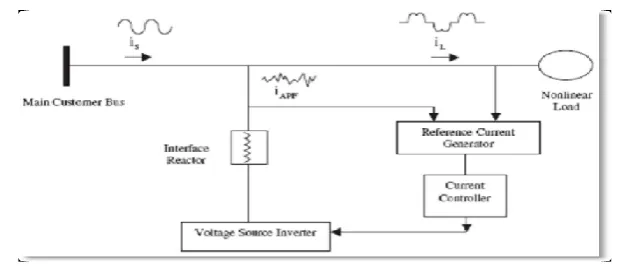
3.3.1 Shunt Active Filter:
The active filter concept uses power electronic equipment to produce harmonic current components that cancel
the harmonic current components that cancel the harmonic current components from the nonlinear loads.. In this
configuration, the filter is connected in parallel with the load being compensated .Therefore the configuration is
often referred to as an active parallel or shunt filter. Fig 3 illustrates the concept of the harmonic current
cancellation so that the current being supplied from the source is sinusoidal. The voltage source inverter used in
the active filter makes the harmonic control possible. This inverter uses dc capacitors as the supply and can
switch at a high frequency to generate a signal that will cancel the harmonics from the nonlinear load. The
active filter does not need to provide any real power to cancel harmonic currents from the load.
The harmonic currents to be cancelled show up as reactive power. Reduction in the harmonic Voltage distortion
occurs because the harmonic currents flowing through the source impedance are reduced. Therefore, the dc
capacitors and the filter components must be rated based on the reactive power associated with the harmonics to
be cancelled and on the actual current waveform (rms and peak current magnitude)
that must be generated to achieve the cancellation.
Fig.Shunt Active Power Filter
The current wave form for canceling harmonics is achieved with the voltage source inverter in the current
controlled mode and an interfacing filter. The filter provides smoothing and isolation for high frequency
gate bipolar transistors (IGBT‟s) in the inverter. Control of the current wave shape is limited by the switching
frequency of the inverter and by the available driving voltage across the interfacing inductance.
The driving voltage across the interfacing inductance determines the maximum di/dt that can be achieved by the
filter. This is important because relatively high values of di/dt may be needed to cancel higher order harmonic
components. Therefore, there is trade –off involved in sizing the interface inductor. A large inductor is better for
isolation from the power system and protection from transient disturbances. However, the larger inductor limits
the ability of the active filter to cancel higher order harmonics. The inverter in the Shunt Active Power filter is a
bilateral converter and it is controlled in the current Regulated mode i.e. the switching of the inverter is done in
such a way that it delivers a current which is equal to the set value of current in the current control loop. Thus
the basic principle of Shunt Active Filter is that it generates a current equal and opposite to the harmonic current
drawn by the load and injects it to the point of coupling there by forcing the source current to be pure sinusoidal.
This type of Shunt Active own Filter is called the Current Injection Type APF.
Fig.Shows Need Shunt Active Filter
3.4 Harmonic compensation
3.4.1 Current Harmonic Compensation:
Current harmonic compensation strategies are exceptionally important .Current harmonics are greatly reduced
by the compensation of voltage harmonics at the consumer‟s point of common coupling. The reduction in
current harmonics is not only important for reasons such as device heating and reduction in life of devices but
also in design of power system equipment. One of the major design criteria covers the magnitude of the current
and its waveform. This is to reduce cable and feeder losses. Since the root mean square (RMS) of the load
current incorporates the sum of squares of individual harmonics, true current harmonic compensation will aid
system designers for better approached power rating equipment.
3.4.2 Harmonic detection and extraction:
A shunt active filter acts as a controllable harmonic current source. In principle, harmonic compensation is
achieved when the current source is commanded to inject harmonic currents of the same magnitude but opposite
III. SHUNT ACTIVE POWER FILTER
3.1) Introduction to Open Loop System:
I n typical distribution systems the proliferation of diode rectifiers has resulted in serious utility interface issues
as well as power quality degradation such as supply current and voltage harmonics, reactive power, flicker and
resonance problems in industrial applications. Voltage distortion due to current harmonics is becoming a major
problem for the utilities at distribution levels. Utilities more frequently encounter harmonic related problems,
such as higher transformer and line losses, reactive power and resonance problems, required derating of
distribution equipment, harmonic interactions between customers or between the utility and load, reduced
system stability and reduced safe operating margins. This has led to the proposal of more stringent requirements
regarding power quality; standards such as IEEE-519 [5] reflect these preoccupations. Passive filters are being
used widely for harmonic elimination. However, they may create system resonances, need to be significantly
overrated to account for possible harmonic absorption from the power system, must be coordinated with reactive
power requirements of the loads and need a separate filter for each harmonic frequency to be cancelled. The
concept of using active power filters to mitigate harmonic problems and to compensate reactive power was
proposed more than two decades ago. Since then the theories and applications of active power filters have
become more popular and have attracted great attention. The concept of using active power filters to mitigate
harmonic problems and to compensate reactive power was proposed more than two decades ago.
Fig:5 Main block diagram of an open loop system
Without the drawbacks of passive harmonic filters, the active power filter appears to be a viable solute for
reactive power compensation as well as for eliminating harmonic currents. The schematic diagram of a power
conditioner system employing shunt APF is as shown above. The composite load includes a three-phase diode
rectifier, and a three phase R load. The ac side inductance is often sufficiently provided by the connected
transformer. The unbalance in the present study is created by connecting resistive load between two phases.
IV.BENEFITS OF POWER FACTOR IMPROVEMENT:
i) Reduction in kVAR Demand
ii) Reduction in kVA Demand
iv) Reduction in Line Current
v) Reduction in Cable Size
vi) Reduction in Switchgear rating vii) Reduction in Power Loss
V.CONCLUSION
A current decomposition technique based on instantaneous power theory for shunt active power filters is
studied, a simulink model is designed and total harmonic distortion is calculated using FFT analysis. Active
power filter which has been used here monitors the load current constantly and continuously adapt to the
changes in load harmonics. The performance of three phase shunt active power filter using instantaneous power
theory with PI and hysteresis current controller is explained in this paper.
REFERENCES
[1] Schlabbach, D. Blume, and T. Stephanblome, “Voltage Quality in Electrical Power Systems”, ser. PEE
Series. NewYork: IEE Press,2001.
[2] L. Gyugyi and E. C. Strycula, “Active AC power filter,” in Proc. IEEE IAS Annu. Meeting, 1976, pp.
529–529.
[3] H. Akagi, Y. Kanazawa, and A. Nabae, “Generalized theory of the instantaneous reactive power in
three-phase circuits,” in Proc. IEEE and JIEE IPEC, 1983, pp. 821–827.
[4] Y. Komatsu and T. Kawabata, “Experimental comparison of pq and extended pq method for active power
filter,” in Proc. EPE, 1997, pp.2.729–2.734
[5] V. Soares, P. Verdelho, and P. D. Marques, “Active power filter control circuit based on instantaneous
active and reactive current id – iq method,” in Proc. IEEE PESC, 1997, pp. 106–101.
[6] B. Singh, K. Al-Haddad, and A. Chandra, “A new control approach to three-phase active filter for
harmonics and reactive power compensation,”
[7] IEEE Trans. Power Syst., vol. 13, no. 1, pp. 133–138, Feb. 1998. “Active power filters for non-linear
loads”.Instantaneous Power Theory Based Active Power Filter: A Mat lab/ Simulink Approach.
[8] Generalized theory of the instantaneous reactive power inthree-phase circuits,” in Proc. IEEE and JIEE
IPEC, 1983, pp.821–827.
[9] Harashima F., Inaba H. and Tsuboi K., “A close-loop control system for the reduction of reactive power
required by electronic converters,”Toshiba Electric Co., Tokyo, Japan, Oct. 1975.
[10] Knoell H., “3 kW-switch-mode supply providing Sinusoidal mains current and large range of dc-output,”
PCI, Munich, Germany, 1980.
[11] Nastran J.. “Active Power Filter,” dissertation presented at the Faculty of Electrical Engineering,