756 | P a g e
AUTOMATIC POWER FACTOR IMPROVEMENT
USING EMBEDDED SYSTEM
Aravindan V
1, Venkatesh R
2, Kalyani Sundaram S
31,2,3
UG Scholar, Department of EIE, SNS College of Technology, Coimbatore, Tamil Nadu, (India)
ABSTRACT
The objective of this project is to moniter and control the cosine angle between the voltage and current in order to save the electric energy.This project is very useful in the industries where heavy inductive loads are used.If the powerfactor is less than unity the line current is greater and increases the KVA demand.This attracts penalty
imposed by Electricity Board.
Keywords: Electric Energy, Power Factor, Cosine Angle, KVA.
I.INTRODUCTION
1.1 Need of Project
This project is used to monitor and control the cosine angle between the voltage and current in order to save the electric energy. If the power factor is less than unity, the line current is greater than the load current, which causes heating of switch contacts, cables etc. As also it causes to rise in reactive power, the KVA demand increases.
This leads to double payment to EB office and this leads to penalty charges. So this project is very useful to the industries where inductive loads are used.
At present maximum number of industries use power factor controller to maintain the power factor. Those power factor controller use normal relays in their circuits for the switching purposes. Since those normal relays have a low switching speed, the power factor cannot be controlled continuously without steps.
757 | P a g e
II. OVER VIEW OF AUTOMATIC POWER FACTOR IMPROVEMENT USING EMBEDDED
SYSTEM
2.1 Block Diagram
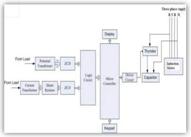
Fig 1.1 Block diagram of Automatic Power Factor Improvement Using Embedded System
2.2 Block Diagram Description
1.Potential transformer
Voltage to the motor is measured with the help of a potential transformer. The potential transformer will convert the mains supply voltage to low voltage ac. That ac voltage is given to zero crossing detectors
2. Current transformer
The current transformer will convert the load current in to lower values that current output will be converted in to voltage with the help of the shunt resistor. Then the corresponding the ac voltage is given to zcd.
3. Zero crossing detectors
758 | P a g e
4. Logic circuit
In this logic circuit an ex-or gate is used. This ex-or gate is used for calculation. This intakes the output from the two comparators and makes a calculation. Then the square wave signal is given to logic circuit in order to find timing between the two pulses. Then the corresponding pulse output is given to microcontroller.
5. Micro controller
The microcontroller is the flash type reprogrammable microcontroller in which we have already programmed with our objectives the microcontroller received the corresponding square pulse from the logic circuit and performs the mathematical calculation on the pulse to find the cosine angle.
6. Lcd display
2x16 lcd display used to display the power factor value.
7. Driver circuit
This circuit is used to drive the thyristor.
8. Thyristor
Thyristor is a semiconductor switching device and it is used for adding and cutting the capacitor.
9. Capacitor
The capacitor is mainly used to improve the power factor when normal power factor is going lagging condition.
III.WORKING PRINCIPLE
Voltage to the motor is measured with the help of a potential transformer. The potential transformer will convert the mains supply voltage to low voltage AC. That AC voltage is given to zerocrossing detectors. Current consumed by the motor is measured with the help of a current transformer.
The current transformer will convert the load current in to lower values that current output will be converted in to voltage with the help of the shunt resistor. Then the corresponding the AC voltage is given to Zero crossing detectors.
The zero crossing detectors are used to convert the input sine wave signal to corresponding square wave signal. Then the square wave signal is given to logic circuit in order to find timing between the two pulses. Then the corresponding pulse output is given to microcontroller.
Here the microcontroller is already programmed with our objectives. The microcontroller receives the corresponding square pulse from the logic circuit and performs the mathematical calculation on the pulse to find the cosine angle.
759 | P a g e
The fixed capacitor is connected across the Thyrister output terminal. When Thyrister output terminal is shorted through the capacitor the lagging angle is compensated through lading angle due to the capacitor. If the cosine angle crosses the unity and moves towards the leading angle suddenly the capacitor is cut off and the angle moves towards the unity. Thus the power factor is maintained efficiently
IV.TEST RESULTS
4.1 Load Test (Without Capacitor)
Table:1.1 Test results
4.2 Load Test (With Capacitor)
Table:1.2 Test results
4.3 Bar Chart
Fig:1.2 Bar chart
Load status Line voltage
Line current
Input power
cosφ % ofŋ
No load 230 0.5 20 0.2 -
Full load 230 0.75 130 0.7 85
Load status Line voltage
Line current
Input power
cosφ % ofŋ
No load 230 0.5 20 0.9 -
760 | P a g e
From the bar chart we can understand that when an industry run without a power factor controller the power consumption will be high and so much loss will occur to the EB and to the industry. By introducing the power factor controller the power will be 80% saved and power losses will be no more.
4.4 Graph
Fig:1.3 Graph
The above graph shows relation between the current and the conductor. From the graph we can know that when the current increases the conductor size also increases.
Thus when a power factor controller is fixed the current in the line is too minimum so the size of conductors will reduces and the initial cost also reduced.
V. DRAWBACK
5.1 HARMONIC DISTORTION
1. The Harmonic Problem
Any device with non-linear operating characteristics can produce harmonics in your power system. If you are currently using equipment that can cause harmonics or have experienced harmonic related problems, capacitor reactor or filter bank equipment may be the solution. Harmonic distortion and related problems in electrical power systems are becoming more and more prevalent in electrical distribution systems.
2.Problems Created by Harmonics
Excessive heating and failure of capacitors, blowing of capacitor fuses, heating of transformers, motors
761 | P a g e
Nuisance tripping of circuit breaker or blown fuses Presence of the third harmonic & multiples of the 3rd harmonic in neutral grounding systems may require
the de-rating of neutral conductors
Noise from harmonics that lead to erroneous operation of control system components
Damage to sensitive electronic equipment
Electronic communications interference
The following is a discussion of harmonics; the characteristics of the problem; and a discussion of our solution.
3.Harmonic Solution
Capacitor, De-tuned Capacitor & Filter Bank products from ABB Control:
Asea Brown Boveri (ABB) is the world's largest manufacturer of dry type low voltage capacitors. ABB Control utilizes this experience in recommending three options to solve the problems associated with applying capacitors to systems having harmonic distortion:
1. Apply the correct amount of capacitance (kvar) to the network to avoid resonance with the source. This may be difficult, especially in automatic systems as the capacitance is always changing.
This solution usually means connecting less capacitance to the system than is actually needed for optimum power factor correction.
2. Install reactors in series with capacitors to lower the resonance below critical order harmonics; i.e., 5th, 7th, 11th & 13th. This design tunes the resonant frequency of the system well below the 5th harmonic and is called a detuned filter bank.
This solution allows the capacitors to operate in a harmonic environment.
3. Filters are recommended if a problem exists with harmonic distortion before the application of power factor correction, or if the harmonic distortion is above the limits recommended in IEEE 519, Guide for Harmonic Control and Reactive Compensation of Static Power Converters.
Tuned filters sized to reduce the harmonic distortion at critical frequencies have the benefits of correcting the power factor and improving the network power quality.
VI.ADVANTAGES
Low power consumption.
The parameters are acquired effectively.
High Efficiency.
Long life of machines.
762 | P a g e
Maintenance is less. Much useful for industries.
VI.CONCLUSION
Now days, in industries 70% of motors are induction motors. In this motor the no load power factor will be low due to the magnetizing current. And so in industries large amount of loss occurs.This project will be helpful in maintaining the power factor of an industry. By adopting this project, mutual benefit is gained over consumer and Electricity Board. We have given clear details about each and every section of this project. The project is economically beneficial one.
REFERENCE
[1] Author Kenneth J Ayala, “Micro controller”, Thomson Delmer Learning.
[2] Author Dr. Raji Kapadia, PIC16F877A Microcontroller & Embedded systems, JAI & CO publishing House, Mumbai.
[3] Author R.K. Agarwal, „Principles of Electrical Machine Design‟, S.K.Kataria and Sons, Delhi,
[4] Author Frank Vahid, „Embedded System Design – A Unified Hardware & Software Introduction‟,John Wiley.
[5] Authors Sriram V. Iyer, Pankaj Gupte, „Embedded Real Time Systems Programming‟, Tata McGrawHill. [6] Author Steve Heath, „Embedded System Design‟, II edition, Elsevier.
[7] Authors Dubey, G.K., Doradia, S.R., Joshi, A. and Sinha, R.M., „Thyristorised Power Controllers‟Wiley Eastern Limited.
[8] Author Lander,W., „Power Electronics‟, McGraw Hill and Company. [9] www.microchip.com
[10]www.google.com [11]www.wikipedia.com
BIOGRAPHICAL NOTES
Mr. V. Aravindan is presently pursuing B.E pre final year in Electronics and Instrumentation Engineering Department from SNSCT, Coimbatore, Tamil Nadu, India.
Mr. R. Venkateshis presently pursuing B.E pre final year in Electronics and Instrumentation Engineering Department from SNSCT, Coimbatore, Tamil Nadu, India.