156 | P a g e
CONJUGATE HEAT TRANSFER ANALYSIS OF
HELICAL COIL HEAT EXCHANGE USING CFD
Rudragouda R Patil
1, V Santosh Kumar
2,
R Harish
3, Santosh S Ghorpade
41,3,4
Assistant Professor, Mechanical Department, Jayamukhi Institute of Technology & Science
2
Assistant Professor, Mechanical Department, Holy Mary Institute of Technology & Science
ABSTRACT
Heat exchangers are one of the important engineering system has variety of applications like0food industries,
chemical0processing, heat recovery systems, and air conditioning. The configuration of helical coil has
very effective for heat0exchangers food industries due to their larger heat transfer area in a smaller
space and has high heat 0transfer coefficient. In the available configurations basic and most
common design consist of a series of stacked helical coil placed in outer cylindrical cover. Ends of
the inner tube connected to the0manifold act as fluid entry and exit locations, outer tube also connected to
the inlet and outlet manifold0becomes the passage of cold fluid. The complex fluid flow inside the helical coil
heat exchanger has offer certain advantages over the straight tube, shell and tube type heat exchangers in
terms of area or volume ratio, with enhancing of heat transfer and mass transfer coefficients. In a heat
exchanger the convective heat transfer between surface and surrounding fluid has a major issue and
take long time to study.
In this particular study, attempt has made to analysis parallel flow through helical tube, where cold fluid
flows in inner tube and outer tube contains hot fluid. Different dimensions of helical coil parameters are
taken into considerations for analyses.
Key words: Heat exchanger, Helical coil, Straight tubes.
I. INTRODUCTION
157 | P a g e
minimize the resistance of fluids flowing through the heat exchangers. In addition of0corrugation in one or both direction to increase surface area and do turbulence can affect its performance.
II. OBJECTIVE
In the present study numerical analysis is carried out to determine the heat transfer characteristics of helical coil heat exchanger by varying the coil parameter0like pitch with different mass flow rates. The main aim is to obtain the higher heat transfer rate that happens when0fluid flows through the helical coil tube.
CFD Analysis of helical heat exchanger for various configurations.
Comparison of parameters like coefficient of heat transfer and temperature variation for various pitch0configurations.
Generation of contours and vectors for temperatures, Pressures and velocities.
III. METHODOLOGY
The methodology involved in carrying out this work is discussed below:
Selection of the material:
Aluminium material with high thermal conductivity and low density is investigated.Modeling
Geometry: 2D and 3D design of the double pipe helical coil is generated according to the dimensions
with CATIA V5 R20.
Domain: A physical domain of desired dimension is generated subjected to the atmospheric conditions
using ANSYS ICEM CFD 15.
FV-analysis: 3D model is meshed and boundary conditions and loading are applied with ANSYS CFX
15.
FV analysis:
FV model is subjected to the required analysis using ANSYS CFXInterpretations of results:
The FV results are analysis with the experimental data.Presentation of data:
the plots, graphs are presented in MS-excel.Prototype model:
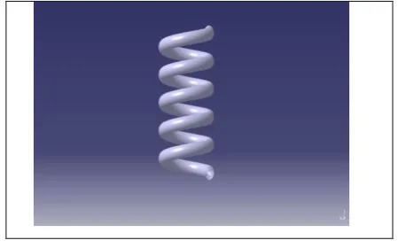
The tool for the final design is realized and the actual component is fabricated by adopting a related manufacturing technology.3.1 Geometry
158 | P a g e
Fig 3.1 3D model of Helical pipe.3.2. Selection of material
Material selection plays vital role in the modeling process. It is one of the most important steps the designer must make before creating the model. To select an appropriate material, the designer should look at their characteristics and behavioral feature required0for the component. The overall performance, efficiency, service life of the structural component depends on the0material used. Following factors should be considered while selecting the material are,
Geometry of the component.
Operating environment.
Required Service life.
Performance required.
Modes of failure.
Loadi.ng conditions.
Cost.
3.3
Boundary conditions
According to the need of the model boundary conditions are used. Inlet Velocity and outlet pressure defined as the inlet and outlet conditions. Parallel flow is the condition taken here, has two inlets and outlets. No slip condition is considered for each wall is separately specified with respective boundary conditions. The turbulence model applied for present analysis was SST model.
Working fluid: water Flow: Turbulent
Inner tube = Cold fluid
Mass flow rate at inner tube inlet = 5 kg/s
Temperature at inner tube inlet = 273.15 K
159 | P a g e
Annulus = Hot fluid
Mass flow rate at outer tube inlet = 2.5 kg/s, 5 kg/s.
Temperature at outer tube inlet = 353.15K
Static pressure at outer tube outlet =1bar
3.4Tetra mesh
The mesh of the model is shown in fig. It depicts that the domain was meshed with tetra cells. Initially a relatively coarser mesh is generated. This mesh0contains triangular faces at the boundaries. Care is taken to use structured tetra cells as much0possible. It is meant to0reduce numerical diffusion as much as possible by structuring the mesh in a well manner, particularly near the wall region. Later on, a fine mesh is generated panel is increased from 0.75 mm to 1.00mm.
3.4.1
Meshing of the mode
IV. RESULTS
The contours for the temperature distribution, velocity distribution, and heat transfer co-efficient distribution on double pipe helical coil are studied first. Then the effect of these distributions on helical coil, heat transfer0enhancement is evaluated by studying the heat transfer co-efficient and temperature0variation on inner coil and outer coil. The result is analyzed for different mass flow rates.
4.1.Velocity Contour
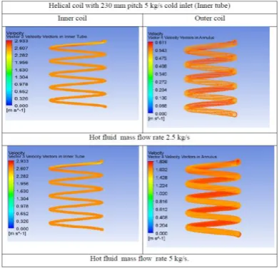
The velocity contours along the length of the coil as shows that velocity profile at a cross section is found symmetric. Subsequently, this uniform velocity pattern changes to a pattern with a high velocity region located at the outer 0side of the coil. This behavior is seen predominantly and continues to develop. It can be seen that, the high velocity0region is present only in outer half cross-section. Area of high velocity region0further reduces the flow gets developed covers approximately1/3
rd
160 | P a g e
Fig 4.1 Velocity distribution of inner and outer coil at 230 mm coil pitch4.2.Temperature Contours:
The temperature distribution of inner and outer helical coil at 230 mm coil pitch for 2.5 kg/s to 5 kg/s mass flow rate is shown in above Figures.The temperature of cold fluid goes on increases from 12.00 K to 20.46 K and hot fluid goes losses its temperature from 23.22 K to13.25 K.As it can seen that temperature of hot fluid decreases as increase in the coil pitch. It is due to curvature effect occurs in helical coil.
161 | P a g e
So this temperature variation is higher for 230 mm pitch with 5 kg/s as compared to 2.5 kg/s. Thus from these contours it shows that, thermal loading on a 230 mm pitch with 5kg/s is high.
V.CONCLUSION
By observing above results comparing with practical values at different coil pitches the heat transfer coefficient increases due to increase in pitch of0helical coil at different mass flow rates. The heat transfer coefficient causes for0increases the rise in temperature of cold fluid.
The increase in heat transfer coefficient has been listed for each hot inlet mass flow rate and this heat transfer coefficient can be observed with different hot inlet mass flow rates and for pitch values of 230 mm. Comparing results observed that, for each pitch of helical coil, rise in temperature of cold fluid is more in 230 mm coil pitch with 5kg/s. Due to increases in mass flow rate i.e. increase in velocity causes increase heat transfer coefficient.
Table : Rise in total temperature
REFERENCES
1. Prakash J Sakariya, Prof. Priyanka M Jhavar, Prof.Ravi D Gujarati. Review paper on analysis heat transfer in spiral plate heat exchanger using experimental and CFD. vol.
2. J.S. Jayakumar, S.M. Mahajani , J.C. Mandal , Kannan N. Iyer , P.K. Vijayan. CFD analysis of single-phase flows inside helically coiled tubes.Computers and Chemical Engineering 34 (2010) 430–446. 3. Mr. Jeevan Wankhade, Ms. Madhuri Tayde, Prof. Shylesha Channapattana. Helically coiled heat
exchanger heat transfer analysis using fluent 14.0 vol. 2, issue 11, (2015).
4. S.D.sancheti Dr.P.R.suresha Experimental and CFD estimation of heat transfer in helically coiled heat exchangers,(Mar-2012) 277-280.