Abstract—To improve Winkler foundation model that ignores the shear effect of the layered soil, the second soil elastic parameter is introduced to take into account the shear deformation of soil. An initial parameter method is developed to solve the dynamic differential equation of lateral vibration for a pile which is embedded in a layered Pasternak foundation. By means of the transfer matrix method, the relationship of the lateral displacement, rotation angle, bending moment and shear force between the pile head and pile tip is investigated. Based on the boundary conditions as well as the continuity conditions, the accuracy of the theoretical derivation and the calculation program of the natural frequency has been verified through an engineering example. The method in this paper gives much better results in contrast to the energy method and equivalent depth method. The analysis also demonstrates that the role of soil shear makes the dynamic stiffness of a pile increase when compared with one in the Winkler foundation model.
Index Terms—Bridge pier, natural frequency, pasternak foundation, soil-foundation dynamic interaction.
I. INTRODUCTION
The natural frequency reflects the inherent vibration characteristics of the structure. At the same time, the soil-structure interaction (SSI) under impact or seismic excitations is a key issue in the dynamic problems of pile foundation. Therefore attention has been paid to the natural frequency of a pile considering pile-soil dynamic interaction. Various Models, such as the continuum model [1], the Winkler model [2], [3] and the finite element model [4], [5] have been presented to study the dynamic interaction problems. The continuum model only applies to the homogeneous foundation model, on the other hand, the numerical model cannot be extended to large practical projects because of high cost. The Winkler foundation has experienced widespread applications in which the pressure at that point is only related to the deflection at that point, in addition to the clear physical concept and simple calculation. In contrast to the three-dimensional analysis results, Kagawa [6] established the coefficients of the pile-soil model. Some domestic scholars compared this model in consideration of the shear effect [7] of a pile and layered soil [8]with the finite element results. However, based on a series of independent springs and dashpots, the Winkler model ignores the shear behavior of soil, that is to say, it cannot describe the continuous deformation of a practical foundation, which is not theoretically rigorous.
Manuscript received December 5, 2016; revised April 1, 2017. This work was supported by the Natural Science Foundation of Jiangsu Province, China (SBK201322459) and the Key University Science Research Project of Jiangsu Province, China (12KJA580002).
The authors are with the College of Civil Engineering, Nanjing Tech University, Nanjing 211816, China (email: [email protected], [email protected]).
Combing spring-dampers with the incompressible pure shear element that only result in vertical shear deformation, the Pasternak foundation model introducing a second foundation parameter improves the previous model, namely, it overcomes the limitation of the Winkler model. Jue Wang [9]made vibration impedance analysis on a pile considering soil shear effect in layered foundation which indicated it was necessary to make use of two-parameter foundation model. In addition, the vibration of pile foundation is that of infinite number of degrees of freedom system. Considering the complexity of pile-soil interaction, the primary circular frequency of a pile simplified to the cantilever structure is solved by the equivalent depth method [10] which presented a simplified analytical formulation. Weifeng Sun [10]adopted the energy method [11] to simplify the layered foundation into soil springs with equivalent stiffness coefficient as well as obtained the results compared with the energy method and the measured data. In this paper, a study is focused on vibration of a pile in the two-parameter foundation. The method of initial parameter and transfer matrix are developed to acquire the differential equation of lateral vibration of a pile. According to the boundary condition and continuous condition, the accuracy of the natural frequency formula is verified by an engineering example.
II. FORMULATIONS
A. Vibration of the Pile below the Ground
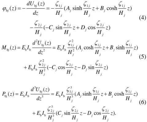
To better understand the behavior of dynamic interaction of the bridge pier in Pasternak foundation model, lateral vibration model of the pile below the ground is shown in Fig.1. The Euler-Bernoulli beam theory is used to describe the vibration of a pile. When the piers are impacted, the displacement and deformation will be transmitted to the superstructure through the bearings while the deformation of the superstructure will also restrain the piers correspondingly. In such a case, springs with compressive rigidity and rotational stiffness can be used to represent the lateral restraint to the piers. The pile below the ground is divided intoNsegments along its shaft according to the specific distribution of the stratum. Each segment with more or less uniform mechanical property is taken into account as a system composed of an incompressible shear layer, which is connected through infinitely close linear springs and dashpots.
Natural Frequency of Bridge Pier Considering Soil Shear
Effect in Layer Foundation
Ying Sun and Ding Zhou
The dynamic equation of the jth segment, without consideration of the damping effect, can be expressed as
4 2 2
b b b
b b 4 b b 2 b 2
( , ) ( , ) ( , )
( , ) 0.
j j j
xj j xj
u z t u z t u z t
E I A k u z t g
z t z
Fig. 1.Lateral vibration model of the pile below the ground in Pasternak foundation.
where ubj( , )z t is the transverse deflection of the jth
segment and bAb is the mass per unit length along the single pile; E Ib b is the flexural stiffness of the pile. gxj and kxj are the shear stiffness and the compressive stiffness of the jth layer, respectively. G gxj kxj is defined as the ratio of the elastic foundation parameters in the Pasternak model, whose algebraic expressions have been developed in [2]. During the steady-state harmonic vibration, the deflection of a pile can be expressed as
b( , ) bj( ) i t j
u z t U z e , where i 1, is the frequency of the excitation. In such a case, equation (1) becomes
4 2 2 4
b b
b
4 2 2 4
( ) ( )
( ) 0.
j j j j
j
j j
d U z d U z
U z
dz H dz H
(2)
where j and j are defined by jHj Gkxj E Ib b
and 4 2
b b b b
j Hj A kxj E I
, respectively. The general
solution for (2), which exists four characteristic roots, is obtained by
1 1
b
2 2
( ) cosh sinh
cos sin .
j j
j j j
j j
j j
j j
j j
U z A z B z
H H
C z D z
H H
(3)
in which
4 4 2
2j ( j/ 4) j ( j/ 2)
, 2 4 4
1j ( j / 2) ( j / 4) j .
j
A ,Bj ,Cj,Djare undetermined coefficients which are determined by the boundary condition between the head of the pile below the ground and the tip of the pile above the ground.
According to the deflection curve differential equation of the beam, rotation angle bj( )z , bending moment Mbj( )z
and shear force P zbj( ) of the pile are
b 1 1 1
b
2 2 2
( )
( ) ( sinh cosh )
( sin cos )
j j j j
j j j
j j j
j j j
j j
j j j
dU z
z A z B z
dz H H H
C z D z
H H H
(4)
2 2
b 1 1 1
b b b 2 b b 2
2
2 2 2
b b 2
( )
( ) ( cosh sinh )
( cos sin )
j j j j
j j j
j j
j
j j j
j j
j j
j
d U z
M z E I E I A z B z
H H
dz H
E I C z D z
H H
H
(5)
3 3
b 1 1 1
b b b 3 b b 3
3
2 2 2
b b 3
( )
( ) ( sinh cosh )
( sin cos ).
j j j j
j j j
j j
j
j j j
j j
j j
j
d U z
P z E I E I A z B z
H H
dz H
E I C z D z
H H
H
(6)
According to the initial parameter method, we define a local coordinate system for jth segment to represent the internal forces and deflections at the top of the segment as
b
1 2 b
2 2 1 2 b b b
3 3 1 2 b b b 3 3
( )
( )
.
( ) ( )
( ) ( )
j j j
j j
j j j
j j
j j j 2 j 2 j
j j
j j
j j j
j j
U 0 A C
0 B D
H H
M 0 E I A C
H H
P 0 E I B D
H H
(7)
Thus, the four unknown coefficients can be acquired from (3)-(7) as follows:
2 2
2 1 b 1 b b b
2 2
2 2 b 2 b b b
2 2
1 1 b 1 b b b
2 2
1 3 b 3 b b b
(0) (0)
(0) (0) /
(0) (0) /
(0) (0) /
j j j j j j j
j j j j j j j
j j j j j j j
j j j j j j j
A k U H k M E I
B k H k P E I
C k U H k M E I
D k H k P E I
(8)
in which 1
2 2
1 2
1
( )
j
j j
k
, 2 2 3
1 2 1
( )
j j
j j j
H k
,
3 2 3
1 2 2
.
( )
j j
j j j
H k
The relationship of deflections and internal forces between the top and the head at the jth segment by substituting (8) into (3)-(6) can be written in a matrix form, as shown below
b b
b b
b
b b
b b
( ) (0)
( ) (0)
.
( ) (0)
( ) (0)
j j j
j j j
j
j j j
j j j
U H U
H
P H P
M H M
T (9)
where the expression of each element in matrix Tbj is given in Appendix.
deflections and internal forces between the head and the tip of a pile by means of the transfer matrix method, which is recommended as
b b
b b
b
b b
b b
( ) (0)
( ) (0)
.
( ) (0)
( ) (0)
U L U
L
P L P
M L M
T (10)
where TbT TbN bN1T1 is called the lumped transfer matrix.
B. Vibration of the Pile above the Ground
When the compressive stiffness in the (1) is zero, the dynamic equation of the ith segment of the pile above the ground can be derived as
4 2
u u
u u 4 u u 2
( , ) ( , )
0.
i i
i i i i
u z t u z t
E I A
z t
(11)
where uui( , )z t is the transverse deflection of the ith
segment and uiAui is the mass per unit length along the pile; E Iui ui is the flexural stiffness of the pile. Lateral vibration model of the pile above the ground is shown in Fig.2.
Fig. 2.Lateral vibration model of the pile above the ground in Pasternak foundation.
Referring to the solution of the dynamic equation of the jth segment as well as the transfer matrix of the pile below the ground, we can establish the transfer matrix Tui of the ith segment above the ground correspondingly, where
u u u u i hi iAi E Ii i
and the expression of each element
in matrix Tui are given in Appendix.
III. CONTINUITYCONDITIONS
According to the continuity condition at the interface of the pile above the ground and that below the ground, equation (12) can be expressed as
u1 b1
u1 b1
u1 b1
u1 b1
(0) (0)
(0) (0)
.
(0) (0)
(0) (0)
U U
P P
M M
(12)
where Ub1 , b1 , Pb1 , Mb1 are amplitude of lateral displacement, rotation angle, shear force and bending moment of the first segment of the pile above the ground. Applying the dynamic equation of the ith segment on (3)-(6), equation (13) is
1 1 1 1
1 11 21 1 1 1 1
1 1 1
2 2 2
1 11 21
u1 u1 2 1 1 b b 2 1 2 1
1 1 1
3 3 3
1 11 21
u1 u1 3 1 1 b b 3 1 3 1
1 1 1
( )
.
( ) ( )
( ) ( )
a c A C
b d B D
h H H
E I a c E I A C
h H H
E I b d E I B D
h H H
(13)
in which, E Iu1 u1 is the flexural stiffness of a pile above the ground in the first segment. ai,bi,ci,di are undetermined coefficients which are determined by the boundary condition.
IV. BOUNDARYCONDITIONS
Selecting the segments of the first and second line in the transfer matrix of (10), the following matrix equation is recurrently obtained as
b
b b11 b12 b13 b14 b
b b21 b22 b23 b24 b
b
(0)
( ) (0)
.
( ) (0)
(0) U
U L T T T T
L T T T T P
M
(14)
By applying the boundary condition at the pile tip {U Lb( )0,b( )L 0} to (14), the force-displacement relationship at the pile head below the ground can be acquired
b11 b12 b 13 14
21 22 2
b b b
b b b b3 b24 b
(0) (0) 0
.
(0) (0) 0
T T U T T P
T T T T M
(15)
Combined with (7), the unknown coefficients can be obtained
b b
b b
b b
1 1
11 12
11 21
1 1
21 22
1 1
3 3
11 21
1 1
3 3
1 1
13 14
2 2
23 24 11 21
1 1
2
b b
b b
b b
b 1
b 2
1
b b
0 . 0
A C
T T
B D
T T
H H
E I B E I D
H H
T T
T T
E I A E I C
H H
(16)
2 u
u 2 T u
u Z u
( , )
( , ) ( , ) 0
.
( , ) ( , ) 0
n n
n
n n
n
n z h n z h
z h
n z h n z h
u z t
P z t M K u z t
t
M z t K z t
(17)
in which, uun ,un ,Pun ,Mun are lateral displacement, rotation angle, shear force and bending moment of the segment n of the pile above the ground. During the steady-state harmonic vibration, we have combined with the transfer matrix above the ground. Equation (18) can be written as
u1 2
u1 T
u u1 Z
u1
(0)
(0) 0
0 1 0
.
(0) 0
0 0 1
(0) U
M K
P K
M
T (18)
We definetas
2 T
u Z
0 1 0
0 0 1
M K
K
t T . Equation
(19) is in the following form in consideration of the initial parameter solution of the pile above the ground
1 1
1 1 1 1
11 12 13 14 2
1
u1 u1 1 1
21 22 23 24 2
1 3 1 u1 u1 3 1 1
1
( )
0 .
( ) 0
( )
a c
b d
h
t t t t
E I a c
t t t t
h
E I b d
h
(19)
V. FREQUENCYEQUATION
Equation (13), equation (16) and equation (19) can be
written in the form of BC0 (20), in which
1 1 1 1 1 1 1 1
[a b c d A B C D]T
C . The expression of each
element in matrix B is given in Appendix in detail. To make (20) have nonzero solutions, that is to say,
1 1 1 1 1 1 1 1 0
a、 、 、 、 、 、 、b c d A B C D , the determinant of matrix B must be zero, then the frequency equation about
can be acquired finally.
VI. EXAMPLEVALIDATION
The first order natural frequency of No.6 test pile of Qingdao Bay Bridge was obtained with the energy method in [10]. In this paper, we choose this engineering example to verify the accuracy of the theoretical deduction. Geological conditions of No.6 test pile is shown in Table I.
TABLE I:GEOLOGICAL CONDITIONS OF NO.6TEST PILE.
Layer Number
Bottom Elevation
Layer Thickness
Geotechnical Classification
Bearing Capacity
Friction Resistance 1 -10.54 5.62 Silt Clay 70 20
2 -15.92 5.38 Clay 270 55 3 -18.32 2.4 Coarse Sand 350 70 4 -20.22 1.9 Clay 200 50 5 -33.82 13.6 Gravel Sand 500 100
6 -37.52 3.7
Strongly Weathered
Mudstone
400 80
7 -66.12 28.6
Weakly Weathered
Mudstone
550 110
In ABAQUS analysis, we use Unit C3D8R to simulate the bridge pier and linear Drucker Prager plasticity model for each soil layer setting the shear hardening parameters, as well as tangential friction coefficients at the interface of adjacent layers, regardless of those at pile-soil interface. We employ far-place boundaries to improve the accuracy when simulating the soil boundary, whose diameter is taken as 10 times that of the bridge pier. Fig. 3 gives modal analysis results of No.6 test pile in Pasternak foundation.
Fig. 3. Modal analysis results of No.6 test pile in Pasternak foundation.
The numerical results of MATLAB program are developed to obtain the first order natural frequency of a pile embedded in the Pasternak foundation model in contrast to the theoretical result, which is given in Table II.
TABLE II:ANALYSIS OF FUNDAMENTAL NATURAL FREQUENCY OF NO.6 TEST PILE
Measured
Value Abaqus Matlab
Energy Method
Equivalent Depth Method Frequency 2.000 2.031 2.593 2.670 4.030 Error - 1.55% 29.65% 33.50% 101.50%
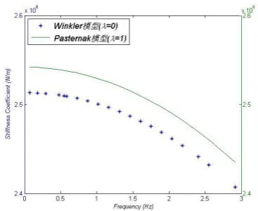
Fig. 4. Comparison of the stiffness coefficient of a pile in Pasternak foundation.
VII. CONCLUTION
In the present analysis, the natural frequency of a pile
embedded in the two-parameter (Pasternak) foundation model has been investigated in the framework of the Euler-Bernoulli beam theory. A pile is divided into nN segments along its shaft with the transfer matrix employed to deal with the layered characteristics of the soil media. The correctness of the theoretical derivation has been proved through a comparative study. The Winkler model is less reasonable than the Pasternak model because it ignores the shear stiffness of the soil layer. Throughout the comparison to the equivalent method, the energy method and the engineering example, the Pasternak model is more accurate in terms of the natural frequency. The numerical results indicate that the dynamic stiffness coefficient in the two-parameter model composed of infinitely close linear
springs and dashpots, which is connected with
incompressible shear layers is obviously larger than that in the single-parameter (Winkler) model.
APPENDIX The elements in matrix B:
11 12 13 14 15 16 17 18
21 22 23 24 25 26 27 28
31 32 33 34 35 36 37 38
41 42 43 44 45 46 47 48
51 52 53 54 55 56 57 58
61 62 63 64 65 66 67 68
71 72 73 74 75 76 77 78
81 82 83 84 85 86 87 88
b b b b b b b b
b b b b b b b b
b b b b b b b b
b b b b b b b b
b b b b b b b b
b b b b b b b b
b b b b b b b b
b b b b b b b b
B
in which,
1 1 11 21
11 12 13 14 15 16 17 18 21 22 23 24 25 26 27 28
1 1 1 1
2 2 2 2
1 1 11 21
31 u1 u1 2 32 33 u1 u1 2 34 35 b b 2 36 37 b b 2
1 1 1 1
1, 0, 1, 0, 1, 0, 1, 0, 0, , 0, , 0, , 0, ,
, 0, , 0, , 0, ,
b b b b b b b b b b b b b b b b
h h H H
b E I b b E I b b E I b b E I
h h H H
13
38 41 42 u1 u1 3 43 1
3 3 3 2 3 2
1 11 21 1 1 1 1
44 u1 u1 3 45 46 b b 3 47 48 b b 3 51 11 u1 u1 2 13 52 12 u1 u1 3 14 53 11 u1 u1 2 13 1
1 1 1 1 1 1
3 1 1 54 12 u1 u1 3 1 1
0, 0, , 0,
, 0, , 0, , , , ,
b b b E I b
h
b E I b b E I b b E I b t E I t b t E I t b t E I t
h
h H H h h h
b t E I
h h
12 1 13 12
14 55 56 57 58 61 21 u1 u1 2 23 62 22 u1 u1 3 24 63 21 u1 u1 2 23 1
1 1 1
3 1 1
64 22 u1 u1 3 24 65 66 67 68 71 72 73 74 75 b11 b14 b b 1 1
, 0, 0, 0, 0, , , ,
, 0, 0, 0, 0, 0, 0, 0, 0,
t b b b b b t E I t b t E I t b t E I t
h
h h h
b t E I t b b b b b b b b b T T E I
h h
112 11 113
76 b12 b13 b b
2 3
1
1 1
2 3 2 3
21 21 21 11 11 11
77 b11 b14 b b 2 78 b12 b13 b b 3 81 82 83 84 85 b21 b24 b b 2 86 b22 b23 b b 3
1 1
1 1 1 1
2 21 87 21 24 b b 2 1
, ,
, , 0, 0, 0, 0, , ,
,
b b
b T T E I
H
H H
b T T E I b T T E I b b b b b T T E I b T T E I
H H
H H H H
b T T E I b
H
21 213
88 b22 b23 b b 3
1 1
.
T T E I
H H
The elements in matrix Tui:
3 2
3 2
u u u u
2
2 u u u
0.5(cosh( ) cos( )) (sinh( ) sin( )) (sinh( ) sin( )) (cosh( ) cos( ))
2 2 2
(sin( sinh( )) 0.5(cosh( ) cos( )) (cos( ) cosh( ))
2 2
i i i
i i i i i i i i
i i i i i i i
i i
i i i i i i
i i i i
i
h h h
E I E I
h
h E I
T
)-u u
3 2
u u u u
3 2
2
u u u u
2
(sin( ) sinh( )) 2
(sinh( ) sin( )) (cos( ) cosh( )) 0.5(cosh( ) cos( )) (sinh( ) sin( ))
2
2 2
(cosh( ) cos( )) (sin( )
2 2
i
i i i i i
i i i i i i i
i i i i i i i i
i
i i
i i i i i i
i i i
i i
h E I
E I E I
h
h h
E I E I
h h
sinh( )) (sinh( ) sin( )) 0.5(cosh( ) cos( ))
2
i
i i i i i
i
h
2 2 1
2 2 2 2
1 2 1 1 2 2 2 1 1 3 2 2 1 3 2 1 2
b b b b
1 1 2 1 2
1 2 2 1 2 2 1 1 3 2 2 3 b b b
( cosh cos ) ( sinh sin ) ( sinh sin ) (cosh cos )
( sin sinh ) ( cosh cos ) ( c
j j j
j j j j j j j j j j j j j j j j j
j j j j j j
j j j j j j j j j j j j
j j
j
H k H
k k k k k
E I E I
k H
k k k
H H E I
T
1
2 1 2 1 1 1 2 2 b b
2 2 2 2 3 3
b b 1 2 1 b b 1 2 1 2 1 2 3 2 1 3 3
1 1 2 2 3 2 2 2 1 1 1 1 1 2
3 3
b b 1
os cosh ) ( sinh sin )
cosh cos
( sinh sin ) ( cos cosh ) ( sinh sin )
j j
j j j j j j j j
j j j j j j j j j j j j
j j j j j j j j j j j j j j
j j j j
H k k
E I
E I k E I k k k
k k
H H H H
E I
2 2 2 2
2 1 b b 1 2 2 2 2 2
1 2 3 2 2 1 1 2 1 2 3 2 1 1 1 2 2
2 (cosh cos ) 2 ( sin sinh ) sinh sin ( cosh cos )
j j j j j
j j j j j j j j j j j j j j j j j
j j
k E I
k k k k k
H H
ACKNOWLEDGMENTS
The financial supports from the Natural Science Foundation of Jiangsu Province, China (SBK201322459) and the Key University Science Research Project of Jiangsu Province, China (12KJA580002) are gratefully acknowledged.
REFERENCES
[1] C. B. Hu and T. Zhang, “Soil-pile interaction in torsional vibrations of a pile in viscious damping soil layer,” Engineering Mechanics, vol. 24, no. 3, pp. 147-153, 2007.
[2] G. Gazetas and R. Dobry, “Horizontal response of piles in layered soils,” Journal of Geotechnical Engineering ASCE, vol. 110, no. 1, pp. 20-40, 1984.
[3] J. Penzien, C. F. Scheffey, and R. A. Parmelee, “Seismic analysis of bridge on long pile,” Journal of the Engineering Mechanics Division, vol. 90, no. 3, pp. 223-254.
[4] G. Wu, “Dynamic elastic analysis of pile foundations using finite element method in the frequency domain,” Canadian Geotechnical
Engineering Journal, vol. 34, no. 1, pp. 34-43, 1997.
[5] L. A. Padron, G. Mylonakis, and D. E. Beskos, “Simple superposition approach for dynamic analysis pf piled embedded footings,” International Journal for Numerical and Analytical Methods in Geomechanics, vol. 36, no. 12, pp. 1523-1534, 2012. [6] T. Kagawa and L. M. Kraft, “Lateral load-deflection relationship of
piles subjected to dynamic loadings,” Soil and Foundation, vol. 20, no. 4, pp.19-35, 1980.
[7] A. F. Hu, K. H. Xie, and Z. R. Xiao, “Analytical solutions for lateral vibration of pile in layered soils considering shear deformation,”
Journal of Zhejiang University (Engineering Science), vol. 39, no. 6, pp. 871-886, 2005.
[8] G. Yu and S. M. Wu, “Dynamic behavior of pile under horizontal vibration,” Journal of Zhejiang University (Natural Science), vol. 30, no. 5, pp. 490-496, 1996.
[9] J. Wang and D. Zhou, “Vibration impedance analysis on single pile considering soil shear effect in layered foundation,” Journal of Nanjing University of Technology (Natural Science), vol. 35, no. 5, pp. 3-8, 2013.
[10] W. F. Sun and W. M. Gong, “Calculating method of natural frequency of pile in layered soils,” Shanxi Architecture, vol. 33, no. 2, pp.16-17, 2007.
[11] X. C. Chen, “Formulas of energy method for the natural frequency of bridge piers,” Civil engineering journal, vol. 32, no. 5, pp. 76-80, 1999.
Ying Sun was born in Rugao city of Jiangsu province in 1993. She graduated with BE in the College of Civil Engineering of Nanjing Tech University in 2015. She has been a Ph.D. candidate in the College of Civil Engineering of Nanjing Tech University. In the present, she devotes most of her time to the research on pile-soil dynamic interaction. Fluid-structure coupling interaction is her another research field in the future. She took part in the project of No.12KJA580002 from the Key University Science Research Project of Jiangsu Province, China and made some progress in research.