Strangely behaving fluidic oscillator
V Tesař1, K. Peszynski2
1Institute of Thermomechanics v.v.i., Academy of Sciences of Czech Rep., 182 00 Prague, Dolejškova 5, Czech Republic 2University of Technology and Life Sciences in Bydgoszcz, Poland
Abstract. Fluidic oscillators became recently of increasing importance for a number of applications. Two alternative variants have been known so far: (a) feedback-loop configurations, with Strouhal number invariance and (b) configurations with a resonator and frequency not dependent on flow rate. Authors tested an oscillator of seemingly quite conventional two-loop design. Surprisingly, its properties fit to neither of the two established categories. Its Strouhal number is not constant and the frequency of oscillation is flow-rate dependent. There is, so far, no reasonable physical explanation for this strange behaviour.
1 Introduction
Fluidic oscillators are devices generating a periodic output flow from supplied steady fluid inflow. Their characteristic feature is absence of any moving or deformable components. This brings a considerable number of advantages. The oscillation is produced in fixed-geometry cavities due to hydrodynamic instabi-lities. Basic ideas upon which they are based have been already there for at least 50 years — but became nearly forgotten. The reason was mainly the role for which they were initially developed : an application in fluidic logic circuits [1]. This has led to a dead end because information processing is more effectively handled by electronics, with which the information-processing fluidics was unable to compete.
Recently, fluidic oscillators became an object of renewed interest in wholly different applications: increasing effectiveness of various industrial processes. The interest is due to the advantages, such as the high frequency range (not limited by inertia of mechanical components in classical hydraulic or pneumatic devices), robustness, reliability, no need of maintenance — and perhaps most importantly, they are inexpensive. The cavity in which the oscillation is generated is nothing more than just specially shaped inlet of the working fluid. The shapes are often complex – but this is no problem nowadays with availability of progressive manufacturing technologies like laser cutting or rapid prototyping.
Examples of industrial processes in which the effectiveness has been recently enhanced by the flow oscillation are the following: increased heat and/or mass transfer rate (in oscillating impinging jets [2] or in heat exchangers), paper making, waste water treatment, oxidative leaching of plutonium, yeast production, hydrodynamic power recovery, sonochemical synthesis, production of biopharmaceuticals, bioreactors, drug
delivery and bimolecular separation, growing unicellular organisms [3], extracting crude oil from „exhausted“ oil wells, and separation of proteins [4]. Typical new use of a fluidic oscillator is generation of micro-bubbles with high intensity of gas diffusion into the liquid. There are several important industrial processes in which the diffusion so far has been the limiting factor. An object of many recent oscillator applications are also actuators for jet-type flow control [5]. Pulsating jets in this application offer a demonstrably higher control action effect than steady jets.
2 The task
The first author (V. T.) has recently received a research grant for a project aimed at generation of microbubbles in a system for biogas upgrading process using CO2 facilitated transport membrane. The small size of the microbubbles is to be achieved by bubble fragmentation using fluidics, on the lines similar to those discussed in [3]. Developing a suitable oscillator for handling typical air flow rate into an model aerator element around 0.5 g/s was an important task in the project.
3 Oscillators with a bistable amplifier:
versions
A
and
B
In a bistable amplifier, the supplied flow forms a jet by issuing from the main nozzle into the interaction region bounded on both sides by an attachment wall and provided there with one of the two control nozzles. The jet cannot flow in a straight direction (- the direction of the nozzle axis) and has to attach by the action of the Coanda effect to one attachment wall. At the downstream end of each attachment wall there is a collector that leads to its exit terminal. In its bistable amplifier role, the jet remains attached – so that the supplied fluid leaves through only one of these two terminals – as long as an input flow pulse comes into the control nozzle on the active side of the amplifier. This pulse switches the jet to the opposite attachment wall. The input flow signal may be quite weak and yet it can switch a much more powerful main flow - this is why the devices is described as an amplifier.
The amplifier is turned into the oscillator by providing a negative feedback. There are several forms of the feedback, all of them respond to some change in the amplifier flowfield and on the basis of this change generate a flow into the control nozzle that detaches the main jet from the active attachment wall. If there were not the attachment bistability effects, such negative feedback action would force the jet to remain in the central, undeflected state. However, in the Coanda-type amplifier, the bistability makes the undeflected flow out of question. The jet does not remain in the central position and the control effect continues moving it up to the opposite attachment wall. There, however, the presence of the opposite side feedback makes a stable attachment also not possible. An analogous negative feedback action is generated on the other side and forces the jet back. The flow from the main nozzle thus oscillates between the two walls and this generates periodic outflows alternatively from one of the two output terminals.
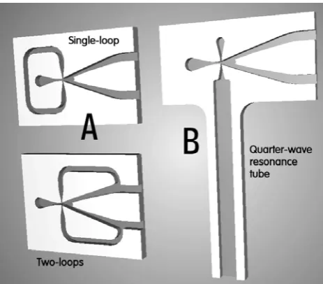
Three most important feedback layouts are presented in Fig. 1. It may be noted that the bistable amplifier is the same in all three cases. At the left-hand side of Fig. 1 there are two versions we may here collectively describe as variant A. Its typical feature is the presence of feedback loop channels. The most popular feedback configuration is the Warren’s circuit [9, 14, 15] with two loop channels. The feedback action they generate is obvious. A part of the flow is removed from the amplifier output and brought by the feedback channel back into the control nozzle on the same side, thus de-stabilising the attached position of the flow in the amplifier. Less often used is the single-loop layout using the pressure difference between the two control terminals if the jet is deflected. This design became known through the work of Spyropoulos [10] – although it was in fact patented also by Warren [11].
In line with almost all oscillatory fluid flow phenomena in fixed boundary geometry flowfield configurations, as long as there are no acoustic resonances, the fluidic oscillators of this variant A are
Fig. 1 Fluidic oscillators based on the concept of a jet-deflection bistable amplifier with a feedback. Typical for the usual variants A with loops, at left, is constant Strouhal number and hence oscillation frequency proportional (more or less) to flow rate. In the new principle with the resonator (variant B at right, [12]) the frequency depends only on the resonator tube length.
governed by the constancy (though sometimes only approximate) of Strouhal number Sh, defined as
w
b
f
Sh
=
(1)- where f is the frequency of generated oscillation in Hz, b is the width of the main (supply) nozzle, and w is the bulk velocity at the exit of this nozzle. As long as it is possible to neglect compressibility of the fluid, the velocity w is simply proportional to the flow rate supplied into the main nozzle. There are applications in which this is an advantage: measuring frequency is easy and so is its conversion (by counting the pulses) into a digital signal. Using this dependence, there are fluidic oscillators developed for the role of digital flowmeters.
On the other hand, in many other applications it is requested keeping the oscillation frequency constant even though it is not possible to guarantee a constant supply flow. In that case it may be useful to use the other variant of the feedback, the variant B shown in its typical appearance at the right-hand side of Fig. 1 – its operating principle described in [12]. Instead of the flow signal propagating in the loops the flow in the amplifier is here switched by the action of pressure waves travelling in a resonance channel connected to one of the control nozzles. Both the other end of the resonance channel and the opposite control terminalare open into the atmosphere (or any suitable large volume of stagnant air). The deflection of the jet issuing from the supply nozzle is
caused by the impact of weak shock waves which are
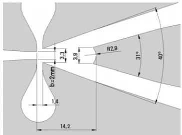
Fig. 2 Contours of the fluidic investigated oscillator. The cavities were laser-cut in a thin, 2mm plate of polymethylmethacrylate PMMA. Geometry of cavities essentially corresponds to the earlier, successfully operated Coanda-effect bistable amplifier.
changes in the resonance channel. Hence, the oscillation frequency is determined by the length L of the resonance channel and the propagation velocity - and does not depend on the flow rate passing through the device. The wave propagation process in the resonance channel with one open end is typical of that occurring in a classical Hartmann quarter-wave resonator, the details and governing laws of which are discussed in [13].
4 Experiments
The key part of the oscillator used by the authors in the tests, the bistable Coanda-effect amplifier, had the layout of its working cavities as shown in Fig. 2 (drawn to scale). The cavities were made by laser cutting in a 2 mm thin plate of PMMA. Geometry of the interaction part of the cavities is specified in Fig. 3. The 2 mm plate was fixed between two 10 mm thick plates as seen in the photograph Fig. 4, tightened together by screws. The upper one of these 10 mm plates was provided with ferrules on which were held ends of silicone rubber tubes. The two feedback loop tubes connected the feedback terminals (on the right-hand side of Fig. 2) with the control terminals (on the left-hand side). The feedback tubes were of 6 mm internal diameter. Six equal-length pairs of feedback tubes were available, with lengths L from 125 mm to 631 mm.
Fig. 3 Interaction cavity of the amplifier from Fig. 2. Behaviour depends mostly on the geometry of these details - where the channel cross-sections are smallest and hence the fluid flow velocity attains the highest values.
In the tests, the oscillator was supplied by compressed air in amounts measured by electronic mass flowmeter FMA1827 (manufactured by OMEGA Engineering, Inc.) capable of measuring the flow rate up to 50 g/min. Oscillation frequency was measured by electret microphone using the audio card in the computer and a software performing the fast Fourier transformation. The basic frequency of the jet switching between the two attachment walls inside the oscillator was apparent in the spectrum as a conspicuous peak – its exact frequency then read digitally.
Fig. 4 Assembled oscillator with the silicone tubing in position. Generated oscillation frequency depends on the lengths of the two feedback loop tubes, which was adjusted prior to an experimental run.
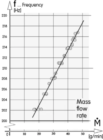
On the next page Fig. 5 presents the values of measured frequency values plotted as a function of the supplied air mass flow rate. There are six groups of data points, each group obtained with different pair of feedback tubes. The data points in each group may be quite well fitted by linear dependence. As usual, the oscillator does not operate at very low flow rates. In the present case the oscillation became irregular and stopped completely at flow rates below ~15 g/min, i.e. 0.00025 kg/s. There is no similar physical limitation on the opposite side of the flow rate range – the reason why the data point for large flow rates are here missing is solely the limited operating range of the used flowmeter.
The strangeness of the oscillator behaviour is in Fig. 5 immediately apparent. The behaviour fits to neither one of known frequency dependences so far reported in literature. The configuration of the oscillator, of course, corresponds to the variant A (Fig. 1) – the amplifier with the two feedback loops. Its characteristic constancy of Strouhal number Sh, eq. (1) should lead in Fig. 5 to data points on straight lines passing through the origin.
Fig. 5 Measured oscillation frequency – with different feedback tubes – as a function of the supplied flow rate. Surprisingly, the oscillation frequency is not proportional to the flow rate (as is usual in the versions A) – but it is also not constant (as in the version B).
generated frequency on the supplied flow rate. This is also not the case – the data points actually show a linear (but not homogeneous) frequency growth with increasing flow rate.
The fitted straight lines in Fig. 5, evaluated by the least squares approach, pass through the intercept point on the vertical co-ordinate line, as is presented in Fig. 5 for the case L = 0.415 m. The set of these intercepts is presented in the next Fig. 6 plotted as a function of the length L of the feedback loop tubes. The data points there are well fitted by a linear relation The ultimate goal of all
Fig. 6 The extrapolated intercept fi (cf. Fig. 5) plotted as a
function of the length L of feedback tubes. The dependence is well fitted by the linear relation. For oscillators of the version B frequencies are inversely proportional to L, which is here obviously not the case.
scientific investigations should be identification of the invariants of the problem. In the version B type oscillators such invariant was found [12] to be the ratio L/λwhereλ is the acoustic wavelength
λ
= wa / f (2)- with wa the propagation speed of sound. This is invariance not the case here, as demonstrated in Fig. 7.
Fig. 7 While the version B oscillators have their oscillation frequency determined by the length L, which is equal to ¼ of acoustic wavelength λ, in the present case the dependence is totally different. This demonstrates that the feedback mechanism in the tested case is not of the resonance variant B.
The ratio L/λ is there plotted as a function of oscillation frequencies. Two different alternative sets of frequencies at each L were chosen for the consideration. On one hand, the wavelength λ was computed from the intercept frequency fi as shown in Fig. 6 — and on the other hand, since the intercept frequency fi is an extrapolation and not a typical frequency of the measured oscillation, as the typical values were taken the frequency values computed from the least-squares fitted lines for the flow rate 30 g/min = 0.0005 kg/s. Neither of these two alternatives did lead to the constant ratio L/λ. Instead, the data values show in Fig. 7 a very rapid decrease
(which could be again, in both shown cases, fitted by straight lines).
The search for the invariants had therefore turned more towards the A – type oscillator variant, with its Strouhal number constancy. An indicator for possible success in the search heading in this direction is the reasonable linearity of the data points in Fig. 5. It is reproduced for a single feedback loops length L = 184 mm in Fig. 8. The data plotting there used an expanded vertical co-ordinate for a better resolution. If the fitted line did pass through zero intercept, this would be a nice case of Strouhal number Sh invariance.
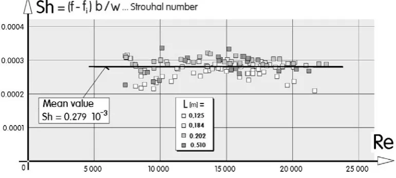
Fig. 9 The linearity from Fig. 8 makes possible characterising the behaviour of the investigated oscillator as a constant Sh version – with non-zero (and very large – Fig. 6) intercept frequency, here deducted in evaluating the Strouhal number
In the next Fig. 9 the values Sh were evaluated for the modified definition, using the difference between the generated frequency and the intercept from Fig. 6. Because of the evaluation from the small difference between two large values, the diagram Fig. 9 inevitably exhibits a large scatter. Nevertheless there is no discernible trend in the data points and the fitted mean value may be considered the desirable invariant.
5. Conclusions
Fluidics – control of fluid flows without action of moving or deformed components – brings many advantages of robustness, reliability and no need for maintenance [16, 17]. Fluidic oscillators are currently in particular demand. Authors investigated a quite conventional design, the two-loop oscillator. Surprisingly, its behaviour fits to neither one of the two established behaviour categories. Strouhal number is not constant and yet the frequency is flow-rate dependent. There is, so far, no reasonable physical explanation for this strange behaviour. The differential Strouhal number constancy may provide a clue, but there is the unexplained quite high frequency at small flow rates. In spite of the strangeness, this behaviour may be actually found useful in a number of possible oscillator applications.
Acknowledgments
The first author (V. T.) was supported by the research plan AV0Z20760514 from the Grant Agency of the Academy of Sciences of the Czech Republic, by the grant TA02020795 provided by the Technology Agency of the Czech Republic, and also by Grant Nr. 101/11/J019 from GAČR — the Czech Science Foundation.
References
1. D. Bouteille, Fluid logic controls and industrial automation ( John Wiley & Sons, 1973)
2. V. Tesař, Chemical Engineering Research and Design 87, 181 (2009)
3. W. Zimmerman et al., Applied Energy 88, 3357 (2011)
5. A. S. Sharma, et al., Journal of Aircraft. 49, 532 (2012)
6. V. Tesař, C.-H. Hung, W. Zimmerman, Sensors and Actuators A: Physical 125, 159 (2006)
7. V. Tesař, Sensors and Actuators A: Physical 138, 394 (2007)
9. R. W. Warren, Negative Feedback Oscillator, (U.S. Patent Nr. 3 158 166, 1962)
10. C. E. Spyropoulos, A sonic oscillator (Proc. of the Fluid Amplification Symp., Harry Diamond Laboratories, Washington D.C., 1964)
11. R. W. Warren, Fluid oscillator (US Patent 3,016,066, 1960)
12. V. Tesař, S. Zhong, R. Fayaz, AIAA Journal (in Print) 13. G. Raman, K. Srinivasan, Progress in Aerospace
Sciences 45,. 97 (2009)
14. V. Tesař, Chemical Engineering Journal 155, 789 (2009)
15. V. Tesař V., Sensors and Actuators A: Physical 138, 394 (2007)
16. V. Tesař, Messen-steuern-regeln 26, (Berlin, Germany 1983)