IJEDR1704034
International Journal of Engineering Development and Research (
www.ijedr.org
)
225
Parametric Optimization of Warm Deep Drawing
Process Aluminium Alloy 1100
1
Srinivas Reddy Thummala,
2Dr. B. Nageshwar Rao,
3A.C.S.Reddy
1 M-tech Advance Manufacturing Systems, 2Associate Professor, 3Head of Department. 1 Department of Mechanical Engineering, A V N Institute of Engineering and Technology,Hyderabad, Telangana State, India
________________________________________________________________________________________________________
Abstract— Deep drawing involves the conversion of flat thin sheet metal blanks into parts of the desired shape. Although
applications of deep drawing processes at different elevated temperatures have not yet been used effectively, it is clear that this process is going to be a very dominant manufacturing application of quality cups produced by this process in this future. Al is primarily used in domestic and also in nuclear applications. Presently high numbers of experiments are conducted to study the formability of this material and heat the specimen to the different temperature of 200ºC, 250ºC, 300ºC. In the present investigation, the load and displacement, temperature relationship are given and found that the load increases as the depth increased, and after reaching the maximum, load gradually decreases in case of the successful cups, but in case of failure, the load decreases suddenly change.
Index Terms— Aluminum alloy 1100, Formability, Deep drawing, Temperature, load, Displacement.
________________________________________________________________________________________________________
I.INTRODUCTION
Sheet metal forming involves the conversion of flat-thin sheet metal blanks into parts of the desired shape. Sheet metal forming processes like deep drawing, bending, etc. are widely used to produce a large number of simple to complex components in automobile and aircraft industries. In the deep drawing which is also called cup drawing or radial drawing, a thin flat sheet is formed into the cup-shaped component by pressing the centre portion of the sheet into die to open using a punch to draw the metal into the desired shape.
The blank can be circular or rectangular or some complex shape. Blank holder is loaded by a blank holder force, which is necessary to prevent wrinkle and to control the material flow rate into the die cavity. The punch is pushed into the die cavity simultaneously transferring the particular shape of the punch and dies in the blank holder-die region and is subjected to compressive and tensile stresses on that portion. When very high blank holding force is applied, the deep drawing process becomes the stretching process. Schematic diagram of deep drawing operation is shown in Fig.1.
Figure.1 Schematic diagram of deep drawing process Figure.2 Schematic diagram of deep drawing process
In stretch forming or stretching, the flange of the flat blank is securely bolted, or in some cases, the material is fixed to the blank holder, and the remaining part of the blank is developed on a tool. To form the part a rigid punch is used. Stretching is distinguished by bi-axial tensile stresses leading to significant reduction in portion. The typical stretching operation is shown in the Fig.1.2.
Bending is the plastic deformation of metal about the linear axis with little or no change in surface area. Bending process is used not only to form such as angle section, flanges, seams and corrugation but also to impart stiffness to the parts by increasing its moment of inertia. It is the most common type of deformation that occurs in almost all sheet metal operations. In deep drawing operation bending of sheets take place over die curvature. The bend zone experiences localized strains which are tensile on the outer side of the neutral axis and compressive on the other side.
IJEDR1704034
International Journal of Engineering Development and Research (
www.ijedr.org
)
226
third deformation zone is uni-axial stretching in the cup wall (plane strain) which causes thinning of metal. In the cup bottom which is subjected to bi-axial tension, the thickness is more or less equal to the initial sheet thickness as shown in the Fig.3.Figure. 3. Deep Drawing operation
The Draw Ratio of a deep drawing activity is calculated as the ratio of blank diameter to the cup diameter. For achieving a very high draw ratio, redrawing and ironing or annealing between successive drawings is performed. The maximum draw ratio can that can be obtained under perfect deep drawing condition is called limiting drawing ratio the LDR and is considered as a good measure of draw ability of the material.
II.EXPERIMENTAL SETUP
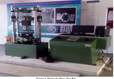
The cylindrical deep drawing test is carried out using the apparatus shown in the Fig.4. The diameter of punch and profile radius of punch is 80mm, and 5mm and those of die are 82.4mm and 5mm respectively.
Figure 4. Hydraulic Press Test Rig
IJEDR1704034
International Journal of Engineering Development and Research (
www.ijedr.org
)
227
from starting position, a maximum heating capacity of heaters is 500º degree Celsius. An experiment carried out in different types of temperature regions. The control panel controls the temperature as per the basis of temperature requirement of the blank.III.MATERIAL SELECTION
Aluminum is the most usual and familiar types of stainless steel. They are easily identified as non-magnetic. They are extremely weldable and formable and can be successfully used from cryogenic temperatures to the red-hot temperatures of furnaces and jet engines. They contain between about 0.05% to 0.2% copper, and they can also contain silicon, zinc and manganese, both of which contribute to their significant corrosion resistance. Were it not for the cost of the nickel that helps stabilize their austenitic structure; these alloys would be used even more widely.
Aluminum has many advantages from a metallurgical point of view. They can be made soft enough (i.e., with a yield strength about 105 MPa) to be easily formed by the use of same tools that work with carbon steel. But they can also be made incredibly strong by cold work, up to yield strengths of over 150MPa. Their austenitic (FCC, face centred cubic) structure is very tough and ductile down to absolute zero. They do not lose their strength at elevated temperatures as rapidly as ferrite (BCC, body centred cubic) iron base alloys. The least corrosion-resistant versions can withstand the normal corrosive attacks on the everyday environment that people experience, while the most corrosion resistant grades can even withstand boiling seawater.
Aluminum Alloys and their Classification: Aluminum (at least 99.0% pure).
Characteristics:
(a) Very high corrosion resistance,
(b) High electrical and thermal conductivity, (c) Good formability
(d) Low strength, and (e) Not heat treatable.
The material used in this study is Aluminum1100 sheet of 0.9 mm thick. 1100 Aluminum is the most commercially pure alloy of all the Aluminum grades. 1100 Aluminum sheet and 1100 Aluminum coil both are obtainable for various applications including chemical storage and processing equipment. Benefits of 1100 Aluminum sheet and coil include a 99 percentages or greater content of Aluminum when compared to that of other Aluminum grades. 1100 is a low strength Aluminum alloy with outstanding corrosion resistance. This type of grade is best used for welding, soldering and brazing but has poor machinability. 1100 Aluminum has excellent finishing capabilities, which is under investigation, is listed in the table1.
Table 1.Chemical composition of Aluminum 1100
Si+Fe Cu Mn Zn Al
0.95 0.05-0.20 0.05 0.10 99
IV.EXPERIMENTAL PROCEDURE
The experiments were carried out on experimental test rig which is specially designed for deep drawing operations at 200ºC, 250ºC, 300ºC temperatures. Aluminum blanks of 0.9mm thickness were cut into circular shape using EDM wire cutting, and deep drawing was carried out on blank diameters ranging from 100mm to 150mm.
Hydraulic press of 20 Tons capacity was used for deep drawing on ASS-316 blanks. Since there is the tendency in the material to change dimensions at higher temperatures, Inconel-600 is used in designing and producing die, punch and blank holder. High-density electrical heaters eight in number are inserted into die holder for heating of empty and die holder. Electrical setup helps to heat specimen plates up to 300º C. Blank is fixed rigidly between the upper and lower dies. Punch is then ramped down to deep draw the blank into a cup. Different temperatures can be achieved for load management and qualitatively bring cups.
Punch: It is fixed on the Universal testing machine with the help of nut bolt system. Punch is made up of low-carbon steel, Hardened by an annealing process and ground over CNC machining for accurate punching radius of 8,7,5,6 Punch draft is shown in the figure.
Die: Die is made up of hardened steel and fixed inside of the die holder, it for to draw the sheet with punch effect.
Die Holder: Die holder is Used to holding the die it is made up of mild steel which can withstand high temperature.8noHigh density Electrical heaters are fixed around the circumference of the die holder diameter of 16 mm and depth of 90 mm inserted for uniform distribution of heat for blank.
The forming load is shifted from the punch radius through the drawn cup wall into the deformation region (sheet metal flange). Due to tensile forces acting on the part wall, wall thinning is prominent and results in an uneven part wall thickness.
IJEDR1704034
International Journal of Engineering Development and Research (
www.ijedr.org
)
228
Figure 4.2 : Assebley of die holder Figure 4.3: Punch
V.RESULTS AND DISCUSSIONS
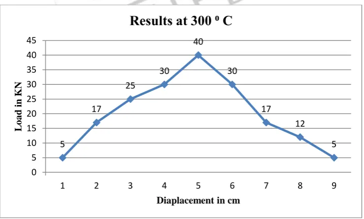
Different types of temperature performed deep drawing process by using the high-density electrical heaters for heating of blank at 200ºC, 250 ºC, 300 ºC temperature forming limit diagram of the cup graph between load, displacement and temperature. The punch capacity increases as the movement of the punch increases, and after reaching the maximum amount, it gradually decreases the gradual decreases of punch load observed. It was also pointed out that the maximum punch pressure increases with new size and it almost linear up to the maximum size of the blank that can be drawn successfully. But the maximum load remains constant whatever may be the size of the blank after limiting the size of the blank for drawn.18 shows the drawn cup from the blanks of 130 mm diameter at room temperature and forming limit diagram (FLD) of the cup. FLD is a graph between the minor strain and significant strain of the sheet metal.
The possibility of fracture in the cup can analyze and can be compared with the forming limit curve (FLC), which appeared in FLD. It shows that the strain in the cup is bellowing FLC, which indicates that the drawing is in the safe zone. There is no indication of fracture in the container walls. The thickness of the cup at punch corner was reduced to 0.9 mm without necking. At 3000C temperatures when the 140mm blank was drawn, with the effect of temperature the strain in the cup has crossed the FLC as shown in Fig. 19 which is not safe. The thickness at punch corner was reduced to less than 0.2 mm and leads to fracture. This breach occurred at the punch corner due to increase in the tensile strain. At room temperature maximum of 130 mm.
Graph 5.1. Load vs Displacement Curve for cup of diameter 120 at 300ºC
5
17
25
30
40
30
17
12
5
0 5 10 15 20 25 30 35 40 45
1 2 3 4 5 6 7 8 9
L
o
a
d
in K
N
Diaplacement in cm
IJEDR1704034
International Journal of Engineering Development and Research (
www.ijedr.org
)
229
Graph 5.2. Load vs Displacement Curve for cup of diameter 110 at 250ºCGraph 5.3. Load vs Displacement Curve for cup of diameter 100 at 200ºC
The experiments have been performed with utmost care, and the results have been plotted into the curves. As per the study, the LDR ratio has been found out to be 2.2 for given punch diameter, i.e. 80 mm. With this information, it can be easily predicted that the blank sizes up to 130 mm at room temperature can be deep drawn conveniently.
VI.CONCLUSION
The Limiting Drawing Ratio with punch diameter 80 mm has been found out to be 2.2 and the safest new size which can be conveniently deep drawn is up to 120 mm with given specifications. When the Aluminum material was subjected to heat treatment before the deep drawing process and heat 250 º C to 300 º C temperature within the die holder with the help of electrical heaters. Just before the deep drawing process. The material which annealed showed us fewer wrinkles, and it was easy to draw. The Aluminum sheet which was not subjected to heat treatment and heating process of blank had more wrinkles. The test was conducted on ALUMINIUM 1100, and its work hardening exponent was found to be quite high. It makes it a highly formable material to be used in industries and future applications. This in turns results in better product quality and improved productivity. This process is being employed in industries to produce different types of components like air filter, missile cone for fighter air crafts; shock observes covers etc. It can be extended to numerous other products and materials. It provides the challenge to researchers to improve the process and equipment for specific industrial applications.
10 15 20 30 50 45 40 30 15 10 5 0 10 20 30 40 50 60
1 2 3 4 5 6 7 8 9 10 11
L
o
a
d in K
N
Displacement in cm
Results at 250 ⁰ C
10 15 20 30 45 60 50 40 30 15 5 0 10 20 30 40 50 60 70
1 2 3 4 5 6 7 8 9 10 11
L
o
a
d in K
N
Displacement in cm
IJEDR1704034
International Journal of Engineering Development and Research (
www.ijedr.org
)
230
VI.ACKNOWLEDGMENT
Great fully acknowledgments to B. Nageshwar Rao,Assosiate Professor for his excellent guidance and am also grateful to Mr A.C.S.REDDY, HOD, SIET, for guiding this project work.
REFERENCES
[1]. M. Jain, J. Allin, and M. J. Bull. "Deep drawing characteristics of automotive aluminium alloys", Materials Science and Engineering: A Vol.256, No.1, pp.69-82, 1998.
[2]. Pourboghrat, Farhang, SenthilkumarVenkatesan, and John E. Carsley. "LDR and hydroforming limit for deep drawing of the AA5754 aluminium sheet", Journal of Manufacturing Processes Vol.15 No.4, pp.600-615, 2013.
[3]. Wen-yu Ma, Bao-yu Wang, Lei Fu, Jing Zhou and Ming-dong Huang. "Influence of process parameters on the deep drawing of the AA6111 aluminium alloy at elevated temperatures" Journal of Central South University vol.22, No.4, pp.1167-1174, 2015.
[4]. Lucian Lazarescu, IoanNicodim, and Dorel Banabic. "Evaluation of drawing force and thickness distribution in the deep-drawing process with variable blank-holding”, In Key Engineering Materials", Trans Tech Publ. Vol.639, pp.33-40, 2015. [5]. Demirci, Halil Ibrahim, CemalEsner, and Mustafa Yasar. "Effect of the blank holder force on drawing of aluminium alloy square cup: Theoretical and experimental investigation", Journal of materials processing technology (JMPT), Vol. 206, No.1 pp.152-160, 2008.