Analysis Techniques for Cyclic
Loading of Oil Field Drill
Strings
Murilo Augusto Vaz
A thesis submitted for the degree of Doctor of Philosophy in The Faculty of Engineering, University of London.
Department of Mechanical Engineering University College London
All rights reserved
INFORMATION TO ALL U SE R S
The quality of this reproduction is d ep en d en t upon the quality of the copy subm itted.
In the unlikely even t that the author did not sen d a com plete manuscript
and there are m issing p a g e s, th e se will be noted. Also, if material had to be rem oved, a note will indicate the deletion.
uest.
ProQ uest 1 0 0 4 4 2 6 0
Published by ProQ uest LLC(2016). Copyright of the Dissertation is held by the Author.
All rights reserved.
This work is protected against unauthorized copying under Title 17, United S ta tes C ode. Microform Edition © ProQ uest LLC.
ProQ uest LLC
789 East E isenhow er Parkway P.O. Box 1346
Demand for cost reduction in offshore hydrocarbon field developments has driven drilling technology research into two areas. The first of these is concerned with using highly deviated drilling to access larger reservoir volum es from fewer platforms whereas the second aims at em ploying drill pipes more efficiently, that is, close to their fatigue limits. This work has two principal objectives - firstly to develop analysis methodologies to calculate cyclic loading in drill strings and secondly to carry out a preliminary investigation of software associated with existing hardware to implement a working drill floor based system.
As part of this work, analytical solutions for the buckling of vertical drill strings when subjected to self weight and to both self weight and torque are presented. These solutions are an extension of Lubinski's^ pioneering work in the 1950's when he presented a solution for vertical drill strings under self weight only and hinged at both ends. This work also uses a power series solution technique to account for self weight with different boundary conditions and with self weight and torque. It is shown that drill string buckling characteristics for the case of self w eight only are significantly altered by the boundary condition applied at the bit. In the case of both self weight and torque, a three-dimensional buckling shape w ith a spiral drill string geometry also significantly changes buckling characteristics. The analytical results are presented in a form that can be readily transferred to computer programs for drill string buckling calculations.
deviated drill strings.
Cyclic loading on oil field drill strings due to longitudinal, torsional and lateral vibrations is investigated and compared with the "statical" cyclic loading caused by a deviated string at a dog-leg. Numerical dynamic analyses of longitudinal and torsional vibrations together w ith quasi static models for lateral vibration and dog-legs are used to compare the cyclic loading induced separately by each of these effects. A linear damage law (i.e.. Miner's rule) is used to calculate the resultant fatigue damage from the cyclic loading. The results show that longitudinal and torsional vibrations may induce significant cyclic loading comparable to that from typical dog-legs whereas the influence of lateral vibration is small. The longitudinal and torsional vibrations are strongly influenced by rotary speed and damping coefficients and can induce significant cyclic loading and rapid accumulation of fatigue damage on drill pipes and collars.
I w ould like to express my gratitude to Professor M. H. Patel, for his encouragement, assistance and valuable suggestions throughout this work. The support and facilities of The Santa Fe Laboratory for Offshore Engineering and its sponsors Santa Fe Exploration (U.K.) Ltd are also gratefully acknowledged.
I am very much indebted to my parents Murillo and Leny, sisters Isabel and Patricia and girlfriend Grace for their support and love.
I acknow ledge the substantial support of the Brazilian Council of Research (CNPq) as sponsors of my study in the U.K. over a period of four years.
pa g e
ABSTRACT 2
ACKNOWLEDGEMENTS 4
LIST OF TABLES 8
LIST OF FIGURES 9
CHAPTER 1 - INTRODUCTION 12
1.1 - Oil and Gas Exploration 14
1.2 - Historical Review of Drilling 15
1.3 - The Rotary Drilling Method 18
1.4 - Directional Drilling 20
1.5 - Horizontal Drilling 21
CHAPTER 2 - REVIEW OF PREVIOUS WORK 30
2.1 - Static Analysis 30
2.1.1 - Stability of Drill Strings in Vertical Holes 30
2.1.2 - Inclined Holes 32
2.1.3 - Use of Stabilisers 34
2.1.4 - Curved Holes 36
2.1.5 - Numerical Methods 38
2.2 - Dynamic Analysis 44
2.2.1 - Harmonic Response 44
2.2.2 - Transient Response 45
2.3 - Vibration Analysis 46
2.3.1 - Longitudinal and Torsional Vibrations 47
2.3.2 - Lateral Vibrations 51
2.3.3 - Precession 52
2.3.4 - Beating Phenomena 56
2.4 - Buckling of Casings, Tubings and Drill Pipes 57
2.5 - Tests and Practical Aspects 61
2.5.1 - Rate of Penetration 61
2.5.3 - Friction Coefficient 62
2.5.4 - Vibration Tests 62
2.5.5 - Practical Aspects 63
CHAPTER 3 - GALERKIN'S METHOD APPLIED TO DRILL
STRINGS 74
3.1 - Dynamic Stability of Drill Strings in Vertical
Holes 75
3.2 - Inclined Holes 80
3.3 - Curved Holes 85
3.4 - Dynamics of Vertical Drill Strings 88
CHAPTER 4 - BUCKLING OF VERTICAL DRILL STRINGS 96
4.1 - Other Boundary Conditions 96
4.2 - Inclusion of Torsion 99
4.3 - Helical Buckling 106
CHAPTER 5 - VIBRAHON ANALYSIS 110
5.1 - Longitudinal Vibration 110
5.2 - Torsional Vibration 116
5.3 - Lateral Vibration 117
CHAPTER 6 - APPLICATION TO CYCLIC LOADING 123
6.1 - Loading Due to Dog-legs 124
6.2 - Loading Due to Vibrations 129
6.2.1 - Longitudinal Vibration 130
6.2.2 - Torsional Vibration 132
6.2.3 - Lateral Vibration 134
6.3 - Practical Example 136
CHAPTER 7 - IMPLEMENTATION ON DRILL FLOOR 152
7.1 - System Hardware 154
7.1.1 - The Drilling Environment 154
7.1.2 - Hardware Alternatives 155
7.1.3 - A Suitable Tag 157
7.1.4 - Deployment Issues 158
7.2.1 - Simulation 160
7.2.2- Preparing Data 161
7.2.3 - Drilling 161
7.2.4 - Extensions 165
CHAPTER 8 - CONCLUSIONS AND RECOMMENDATIONS 173
NOMENCLATURE 175
REFERENCES 181
APPENDIX 1 - Stability of Drill Strings in Vertical Holes 190
APPENDIX 2 - Solution for Drill Strings in Inclined Holes 204
APPENDIX 3 - Calculating Coefficients, Series and Critical
Conditions 209
APPENDIX 4 - Solution Using a '^Quasi-static" Approximation 214
APPENDIX 5 - Generating Pipe Füe 215
APPENDIX 6 - Generating the Initial Geometry 217
Table
1.1.1 Types of Drilling Units
2.1.2.1 Equilibrium in Anisotropic Formations 3.1.1 Critical Weights on Bit (1 = 7.94')
3.3.1 Dimensionless Radial Clearance, 'w2 = 0.5 ' and '1 /r = 0.0'
3.3.2 Dimensionless Radial Clearance for Some Parameters 4.1.1 Critical Weight on Bit
4.2.1 Torque and Self Weight (Dimensionless Units) 4.2.2 Practical Example for Critical Conditions
6.1.1 Drilling Sessions
6.1.2 Accumulated fatigue Damage in Two Hole Profiles 6.1.3 Accumulated fatigue Damage in Heavier Drill String
6.2.3.1 Maximum Bending Stresses
6.3.1 Fatigue Damage Due to Dog-Leg (at 100 rpm)
6.3.2 Maximum Fatigue Damage Due to Longitudinal Vibration
(at 100 rpm)
6.3.3 Maximum Fatigue Damage Due to Torsional Vibration (at 60 rpm)
7.2.3.1 Drill Pipe Characteristics
A l .l Tangency Point
Figure
1.1.1 Jack-up, Drill Ship and Semi-Submersible
1.1.2 Steel Jacket and Concrete Gravity Platforms
1.1.3 Tension Buoyant and Guyed Tower Platforms
1.2.1 Percussion Method
1.3.1 Rotary Drilling Method
1.3.2 Types of Rotary Drill Bits
1.3.3 Drill Collars, Stabilisers and Drill Pipes
1.4.1 Directional Well
1.5.1 Scheme of Horizontal Wells
1.5.2 Sherwood Oil Field
2.1.1.1 Shape of Buckled Drill String
2.1.2.1 Chip Formation in Isotropic and Anisotropic Rocks 2.1.2.2 Drilling in Anisotropic Formations
2.1.2.3 Continuation of .a Dog-Leg
2.1.3.1 Single Stabiliser Analysed 2.1.3.2 Ideal Position of a Stabiliser
2.1.4.1 Constant Curvature Hole
2.1.5.1 Multi Stabiliser Assembly
2.1.5.2 Resultant Force and Bit Angles
2.1.5.3 Stress-Strain Relationship for Gap Element
2.2.1.1 Vibration Paths
2.3.1.1 System of Reference
2.3.1.2 Mobility Method
2.3.1.3 Schematic of System Analysed
2.3.3.1 Precessing Drill String
2.3.3.2 Severity Factor
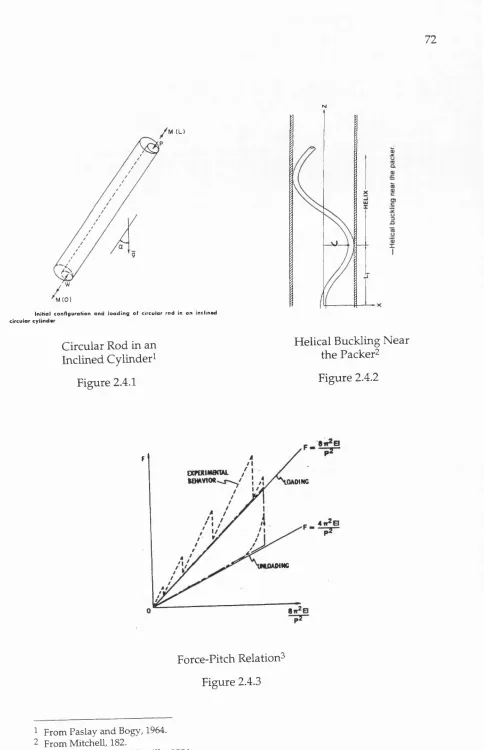
2.4.1 Circular Rod in an Inclined Cylinder
2.4.2 Helical Buckling Near the Packer
2.4.3 Force-Pitch Relation
2.4.4 Rod Geometry
2.4.5 Cylindrical Co-ordinate
2.5.1.1 Rate of Penetration
3.1.1 System of Reference
Figure
3.1.2b Critical Conditions in Lateral Vibration: First Mode 3.1.2c Critical Conditions in Lateral Vibration: Second Mode 3.1.2d Critical Conditions in Lateral Vibration: Third Mode 3.1.3a First Mode of Buckling (T = 7.94')
3.1.3b First Mode of Lateral Vibration ('1 = 7.94') 3.1.3c Second Mode of Lateral Vibration ('1 = 7.94') 3.2.1 Solution for Inclined Holes
3.3.1 Drill String Deflected Shape
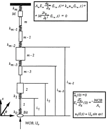
4.2.1 System of Reference
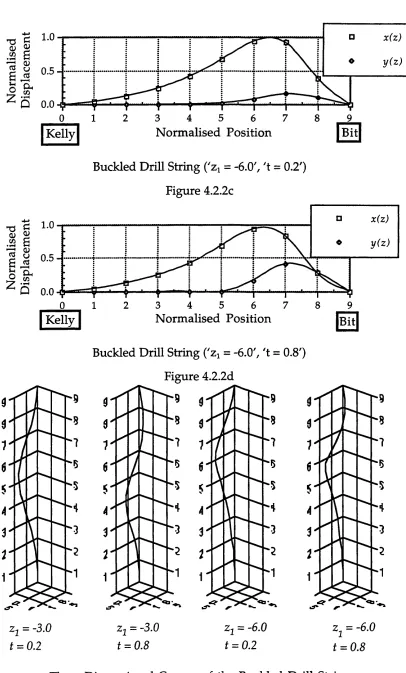
4.2.2a Buckled Drill String ('zi = -3.0', 't = 0.2') 4.2.2b Buckled Drill String ('zi = -3.0', 't = 0.8') 4.2.2c Buckled Drill String ('zi = -6.0', 't = 0.2') 4.2.2d Buckled Drill String ('zi = -6.0', 't = 0.8')
4.2.3 Three-Dimensional Curves of the Buckled Drill String 5.1.1 Schematic of Particular Drill String Design
5.1.2 Schematic of Generalised Drill String Design 5.3.1 Lateral Vibration in Drill Strings
6.1.1a Gradual Dog-Leg
6.1.1b Abrupt Dog-Leg
6.1.2 'a-N' Curves
6.1.3 Hole Profiles
6.1.4a Drill String Arrangement
6.1.4b Drill String Arrangement
6.2.1.1a Longitudinal Vibration
6.2.1.1b Longitudinal Vibration
6.2.1.1c Longitudinal Vibration
6.2.1.2a Longitudinal Vibration
6.2.1.2b Longitudinal Vibration
6.2.1.3a Longitudinal Vibration
6.2.1.3b Longitudinal Vibration
6.2.1.4a Longitudinal Vibration
6.2.1.4b Longitudinal Vibration
6.2.1.5a Longitudinal Vibration
6.2.1.5b Longitudinal Vibration
Figure
6.2.2.2b Torsional Vibration
6.2.3.1a Simulation of Stresses Due to Lateral Motion 6.2.3.1b Simulation of Stresses Due to Lateral Motion 6.3.1a Stress Due to Longitudinal Vibration
6.3.1b Stress Due to Torsional Vibration
6.3.12a Stress along Drill String (Longitudinal Vibration) 6.3.12b Stress along Drill String (Torsional Vibration) 7.1.2.1 Marking on Tool Joint
7.1.2.2 Electrical Conductivity System: Actual and Ideal Signals 7.1.2.3 Proposed Crystal Oscillator Tag
7.1.2.4 Proposed Location
7.1.3.1 Longitudinal Section of Typical Tag
7.1.3.2 Hole in Weld
7.1.3.3 Packer Insert Showing Proposed Antenna Position 7.2.2.1 Drilling Stages
7.2.3.1a Flow Chart of Simulation
7.2.3.1b Flow Chart of Simulation (Continuation) A l.l External Forces Acting on Drill Strings
A1.2 Forces below Section 'MN'
A1.3 Weight on Bit Versus "Bushing" Distance (Dimensionless)
A1.4 Drilling Coefficients Versus Dimensionless 'WOB'
A2.1 Differential Equation Method
A2.2 Iteration Method
A2.3 Large Inclination Reference System
CHAPTER 1 - INTRODUCTION
The continuing demand for cost reduction in offshore hydrocarbon field developments in the North Sea is putting increasing pressure on drilling technology on two fronts. The first of these is concerned with using highly deviated and horizontal drilling to access larger reservoir volumes from fewer surface platforms whereas the second is concerned with using drill pipes more efficiently, that is, close to their fatigue limits. This involves using techniques that have to be able to predict fatigue onset so that such pipes can be taken out of service. This work has two principal objectives - firstly to develop analysis m ethodologies to calculate cyclic loading in drill strings and secondly to carry out an investigation of existing hardware and developing related software to im plem ent a working drill floor based system. These two objectives also show up the main difficulties of this task - how to calculate dynamic stresses with sufficient accuracy during drilling and how to implement a working automated drill floor system that can do this and identify each drill pipe.
tensile strength. This system is, therefore, part of the present trend to automate and de-man drilling rigs.
A brief overview of the structure of this thesis is initially presented. In this first chapter concepts and general information regarding drilling are introduced. Section 1.1 describes some characteristics of oil and gas extraction, it shows how hydrocarbons originated, accumulated in traps and are now sought. Furthermore it also shows how oil w ells are drilled from drilling rigs. Section 1.2 presents a historical review of drilling technology, from the ancient w ells drilled by the percussion method, in China, to present day records at the frontiers of technology - like maximum horizontal reaches, longest wells world-wide and in the North Sea and so on. Section 1.3 depicts the rotary drilling method, its main components (circulating, rotating and hoisting systems) and personnel involved and it explains how the hole is made. Section 1.4 explains how drill strings deviate due to intentional or non-intentional actions - it stresses the applications of directional drilling. Finally section 1.5 describes horizontal drilling, its applications and main advantages. Chapter 2 displays a selection of the most representative work on the mechanics of drill strings, assessing the historical evolution of drilling techniques. This chapter is divided in to static, dynamic and vibration analyses, buckling of drill strings and practical aspects. The literature review tries to cover as many areas as possible that concern the mechanics of drill strings.
Vibration is often blam ed for fatigue failures: chapter 5 provides analytical solutions for longitudinal, torsional and lateral vibrations, giving expressions for the dynamic loading (or stress levels) that allow an estimate of fatigue damage. The models for longitudinal and torsional vibrations include viscous damping and multiple pipe arrangements but the form ulation of lateral vibration assum es continuous pipe and disregards wall confinement effect and friction forces. Chapter 6 accounts for cyclic loading due to vibration and drilling past dog-legs. The Palmgren-Miner's rule of linearly adding fatigue damage for each stress state is applied.
Chapter 7 deals with the implementation of fatigue monitoring on drill floors, it also stresses the importance and benefits of controlling fatigue damage. The technique for using a drill pipe identification or tagging system is demonstrated and it is shown that drilling parameters (weight on bit, rate of penetration, rotary speed and bit trajectory) obtained by a measurement w hile drilling ('MWD') device can be combined to derive cyclic loading and estimate fatigue damage. Proposals for typical hardware and software systems are also discussed. Finally chapter 8 presents a summary of the main results and suggests future topics for study, with emphasis on the application of the research to industry.
1.1 - Oil and Gas Exploration
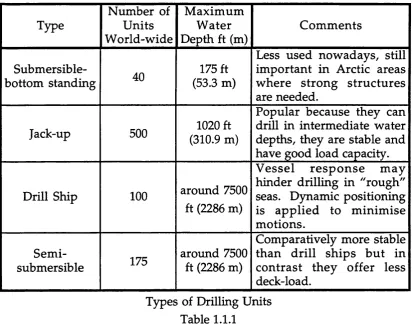
contain hydrocarbons: magnetic, gravity and seismic surveys are run and analysed before the decision to drill is taken. The first two m ethods measure the variation in the earth's magnetic and gravity fields, whereas a seismic survey identifies layers of rocks by measuring the time that sound w aves take to reflect up from them. Ultimately, unless a w ell is drilled, there is no guarantee of the existence of hydrocarbons or if the reservoir w ill be commercially profitable. If surveys reveal promising geological structures, an exploratory ("wild cat") w ell may be drilled. Onshore oil rigs are dismantled and transported to the sites by helicopters or trucks. Offshore mobility is also paramount, several types of drilling units are currently employed (Figure 1.1.1 and Table 1.1.1). Basically the drilling rig is chosen according to its water depth capability, load capacities, environmental conditions and availability of rigs. After the drilling unit is positioned drilling may start and when the reservoir is reached the levels of hydrocarbons are m easured by form ation evaluations (well logging, coring and drill stem testing).
Not so long ago oil was relatively cheap and abundant but when a cartel led by middle-eastern countries started dictating oil prices in the early seventies it became a strategic necessity for each country to develop its own reserves. The race to expand oil production led to surveys in hostile areas such as the Arctic, jungles and especially offshore. In fact, nowadays around 30% of total production comes from offshore oil fields that spread from the Gulf of Mexico to Brunei and from the North Sea to Brazil (Patel, 1989). To extract oil under such adverse conditions and keep costs com petitive, it is necessary to apply new technology and this has promoted advancement of knowledge in oceanography, m eteorology, structural analysis, hydrodynamics, sea-bed soil mechanics and marine geology.
Type
Number of U nits W orld-wide
M axim um Water Depth ft (m)
Com m ents
Submersible-bottom standing 40
175 ft (53.3 m)
Less used now adays, still important in Arctic areas w here strong structures are needed.
Jack-up 500 (310.9 m)1020 ft
Popular because they can drill in intermediate water depths, they are stable and have good load capacity.
Drill Ship 100 around 7500
ft (2286 m)
V e ss e l r e sp o n s e m ay hinder drilling in "rough" seas. Dynamic positioning is app lied to m inim ise m otions.
Sem
i-submersible 175
around 7500 ft (2286 m)
Comparatively more stable than drill sh ips but in contrast they offer less deck-load.
Types of Drilling Units Table 1.1.1
1.2 - Historical Review of Drilling
reached 2000 ft (609.6 m). The percussion m ethod (Figure 1.2.1) encom passes a heavy bit suspended by a cable: the bit is raised and dropped, drilling stops periodically because cuttings and water need to be bailed out. The time required to remove tools, bail out cuttings and water and replace tools increases with well depth. Additionally the cable length limits the tool weight and the rate and length of stroke - hence it becomes uneconomical to drill deep wells (Campbell and Lehr, 1973)
In England a circulation system for rotary drilling w as patented in 1844: water was injected dow n the annulus returning to the surface, with cuttings, through hollow drill rods (Chilingarian and Vorabtur, 1981). In Pennsylvania, 1859, the first w ell intentionally drilled to find oil succeeded in doing so at 69.5 ft (21.2 m) (Baker, 1979). Drilling fluids (m uds) were first used sometime betw een 1887 and 1901, initially em ployed to continuously remove cuttings but the percussion method still prevailed over the rotary drilling method. In Texas, 1901, oil was extracted at a rate of 84000 barrels a day (b/d) (13355 m^ per day) through a rotary drilled well - exceeding by far the average rate of 50 b /d (7.95 m^ per day) of those days. This is considered the milestone which established the predominance of the rotary drilling method. The first offshore w ell was drilled in California, 1897: a drilling rig was placed at a wooden wharf that extended 300 ft (91.4 m) from the beach. The success of this first offshore operation stimulated the erection of many other wharves, the longest one reaching 1200 ft (365.8 m) into the sea. In 1947 the first platform was installed in 20 ft (6.1 m) water depth, out of sight of Louisiana's coast. Nowadays wells have been drilled in water depths above 7500 ft (2286 m) and as far as 200 miles (321.8 km) from land (Baker, 1979).
5624 ft (1714.2 m) water depth (Institute of Petroleum Encyclopaedia, 1983) but in 1987-88 Shell drilled in the Mississippi Canyon at 7520 ft (2292.1 m), establishing a record (Lloyds List, 0 8 /1 2 /8 9 , p. 2). In terms of horizontal drilling, records are broken constantly: in the North West Territories, Canada, 4013 ft (1223.2 m) of hole were drilled at an angle of 88 degrees (Drilling Magazine, July/August 1987, p. 22) but the Danish Underground Consortium drilled the longest (6220 ft or 1895.9 m) horizontal w ell in the Dan field (Lloyds List, 17/07/91, p. 3). The North Sea's longest horizontal w ell was drilled in March 1993 with a horizontal section measuring 7116 ft (2169 m) at a total vertical depth of 9613 ft (2930 m) (Offshore Engineer, May 1993, pp. 28-30). N o doubt this record will be broken again by the time this thesis is printed.
1.3 - The Rotary Drilling Method
The basic principle of the rotary drilling method (Figure 1.3.1) is the simultaneous combination of a downward axial force, called w eight on bit, and bit rotation. The drill string self weight provides the compressive load on bit and the rotary table turns the drill string. Drilling mud, a mixture of water, clays, minerals and chemicals, is pum ped inside the drill pipe and jetted out through the bit nozzles at high speed and pressure. The drilling fluid lubricates and cools bit and pipes and removes cuttings from the bottom. Furthermore, the mud hydrostatic pressure balances formation pressures so as to prevent cave-ins and blow outs. Drilling fluid hydraulics may also affect the rate of penetration. Drilling mud returns to the surface through the annulus between the drill string and the bore hole w all where it is then cleaned and recirculated (Figure 1.3.1). Basically drill strings consist of a drill bit, drill collars, stabilisers and drill pipes (McCray and Cole, 1959). Each of these are described further below :
members. Diamond bits do not have independent parts, they drill by direct abrasion between rocks and the much harder diamonds.
b D rill collars (Figure 1.3.3) are thick pipes placed close to the bit whose purpose is to furnish weight on bit and stiffness to the bottom of the drill string. The total length of drill collars vary considerably but a range of 100 to 900 ft (30.5 to 274.3 m) is most common.
c S ta b ilise r s (Figure 1.3.3) are curved blade elements w hose outer surfaces reduce the apparent radius (they may even fit the w ell bore wall), therefore they increase the stiffness of the bottom hole assembly and improve the ability to drill straight.
d D rill pipes (Figure 1.3.3) are thin walled pipes connected by means of tool joints. They constitute the longest part of the drilling column: the upper end of the drill pipe line is supported by the kelly and the lower extremity is usually connected to a drill collar. Drill pipes are designed to work under tension which can be quite high at the top of the well.
The cross section of the kelly is square or hexagonal so that rotation and torque can be transmitted from the rotary table. As drilling progresses the kelly continuously slides down through the kelly bushing. The kelly is suspended by the swivel; the drill string, kelly and swivel, on their turn, are supported by the hoisting system. The drawworks is a heavy drum around w hich the drilling line (wire rope) is spooled. Crown and travelling blocks consist of sets of pulleys whose aim is to alleviate the load on the drilling line. Drilling derricks must be strong enough to support high loads and wind forces and they should be as portable as possible to facilitate transportation.
the formation, the rotation is continuously increased and the w eight on bit is adjusted by raising or lowering the sw ivel. This procedure is repeated after every 30 ft (9.14 m) of hole is drilled.
1.4 - Directional Drilling
Drill strings are flexible, they tend to bend and deviate the bit away from a straight path. The rotary speed, w eight on bit and drill string arrangement must be selected according to each specific soil and hole geom etry otherw ise the hole may deviate and even spiral three-dim ension ally. The horizontal and vertical angles are called, respectively, azimuth and inclination (Figure 1.4.1). Oil w ells may be thousands of feet deep but the bit trajectory depends strongly on the last portion of drill string that contains the drill collars. Several methods have been employed to change bit trajectory: mechanical devices (e.g., whipstocks and down hole motors), hydraulic techniques (using mud jets at bit) and natural ways (involving knowledge of rock formation and assembly configuration). To maintain bit trajectory, the angle of the resultant force relative to the bore hole axis should be zero, provided a correction for stratified formations is taken into account. It is also important to m inim ise the bit tilt angle in order to im prove bit performance thus reducing bit wear. The bit tilt angle corresponds to the angle that the deflected drill string makes with the bore hole centreline at the bit. Whenever possible, sim ple bottom hole assem blies should prevail over more complicated arrangements.
1.5 - Horizontal Drilling
Horizontal drilling was first attempted in the former USSR in the early fifties when forty three w ells were drilled before the programme was interrupted because of cost overruns. It was resumed by western oil companies in the late seventies, and it is predicted that more than 50000 horizontal w ells w ill have been drilled in this decade, constituting the fastest growing segment in the oil service market (Lang and Jett, 1990). Horizontal drilling reduces the number of platforms required to cover an oil field and production is improved as formation exposure increases. For example, a horizontal drilling programme permitted oil extraction from the Tyra field. North Sea, which primarily supplied gas (Lloyds List, 1 7 /07/91, p. 3). Horizontal drilling is also advantageous when producing oil from thin or geologically complex reservoirs. Figure 1.5.1 presents two schemes for horizontal w ells drilled in the North Sea (Conoco N ew s Release, Feb. 28, 1990). Recently British Petroleum (BP) discovered further reservoirs in its Sherwood oil field (Figure 1.5.2) and driven by environment and cost concerns decided to use long reach techniques instead of building a "drilling island" in Poole Bay (The Sunday Times, May 16,1993).
Typical jac k -u p n g . K ey: a - spud cans; b - ele v atin g racks: c - legs; d - gear units; c - drilling derrick and e q u ip m e n t; ( - ac co m o d atio n ; g - helico p te r p ad ; h - cran es; I - n earby jac k et platform
Typical sem isubm ersible vessel. K ey: a - s u b m erg e d p o n to o n s; b - surface piercing dec k su p p o rt colum ns; c - bracing m em b ers; d - m o oring lines; e - anchor racks; f - deck s tru c tu re ; g - m o o n p o o l: h - ac co m o d atio n ; i - h e lic o p te r p ad ; j - drill pipe racks
Dynamically positioned drill ship. Key: a - drill ship; b - riser; c - blow out preventer; d - well head on sea bed; e - acoustic positioning beacons
Jack-up, Drill Ship and Semi-Submersible^ Figure 1.1.1
Tl
rS
ho
I
D)
PD
CL n
0 CJ
1
?D
O 3 <
4 '
2 D)
& M
g
^ — n —
-4-:rT T-zr l'i.iïïi '.'!
C o iK r c tc Irip c iJ k lr u c lu r c . K f v u - s iiif a c c p l a lf o r n r . b - c o n c rc ic Itip m l s u u c l u r o ; c - g ra v ity b a s e s ; d - d rillin g a n d p r o d u c tio n r is e rs
T y p ic a l o ffs h o re d rillin g a n d p r o d u c t i o n p la tf o r m . K e y : a j a c k e t; b - m o d u le s u p p o r t f r a m e ; c - p ile s ; d - d rillin g d e r r i c k , e - h e lic o p te r p a d ; f - d rillin g a n d p r o d u c tio n e q u i p m e n t ; g - f la r e s ta c k ; h - s u rv iv a l c r a f t ; i - re v o lv in g c r a n e s ; j - p ile g u id e s ; k - p ile
A typical tensioned buoyant platform . Key. a - surface platform; b tensioned tethers; c - tether foundations; d - tem plate on seabed: e - marine risers
Guyed tower production platform. Key. a - slender t
foundation; c - mooring lines; d - sea bed clump weights; e - anchors
tower; b - spud
Tension Buoyant and Guyed Tower Platforms^ Figure 1.1.3
CHAGBAMMAnC AND NOT TO S C A L P
CA St£ TOOL v n USCO ST K k . wéwvwll
Percussion Method^ Figure 1.2.1
Rotary Drilling Method^ Figure 1.3.1
^ From British Petroleum Company Limited, 1970.
DRAG BITS
pnusiEKU
Rolling-Cutter Bit Diamond Bit
Types of Rotary Drill Bits^ Figure 1.3.2
( a ) ( b ) ( c ) ( d )
S ta b i lis e r s : (a ) in t é g r a i b l a d e s t a b i l i s e r ( o p e n s p i r a l o n le ft, tig h t s p i r a l o n r ig h t); (b) a n d (c) s l e e v e s t a b i l i s e r s (s te e l b o d y o n left a n d r e p l a c e a b l e s l e e v e o n r ig h t o f (b) a n d h y d r o - s tr in g c o m p o n e n t s o n le ft a n d h y d r o - s tr in g s t a b i l i s e r
o n r ig h t of (c); (d) w e ld e d s t a b i l i s e r ; (e ) r u b b e r s l e e v e s t a b i l i s e r . ( C o u r te s y of C h r i s t e n s e n D rillin g P r o d u c ts )
T O O L J O I N T W E L D A R E A T U B I N G
T O O L J O I N T
t y p i c a l R I C I O I T Y O F n n i l L C O I I A R I I 1 7 I I M I ' I I M A I or U M I L L P i n
S ch em atic diagram o f d rlllp lp e an d d rillcollar. (C o u rte ay o f Sii S m ith T o o l, D ivi sion o f S m ith I n te rn a tio n a i, In c.)
S u r f a c e
lo c a tio n p H o rizo n ta l p lan
I
s
Ï
I
H o riz o n ta l d ito to c a m o n l
W
S
(a) (b) (c)
A d ir e c ti o n a l w ell: (a) t h r e e - d i m e n s i o n a l v ie w ; (b) v e r t ic a l s e c t i o n ; (c) h o r iz o n ta l s e c tio n .
Directional WelP Figure 1.4.1
UK N O R T H VALI ANT FI ELD 4 9 / 1 6 - P 0 5 / 0 3 H O R I Z O NT A L W E L L
V ortical D epth
A v 0 r a g 9 B u ild R a te 1 2 '/TOO"
2 0 0 0 ' H o rizo n ta l s e c tio n
Total m e a s u r e d d e p th 1 1,000'
N E T H E R L A N D S KOTTER FI ELD K 8 / 1 A H O R I Z O NT A L WELL
Depth
O iy » t » r d»t)U> a s '
2000
4000
B u ild R a t e 8-11 .S ' / t o o
620" H o rizo n ta l s e c t i o n
6000
Total m e a s u r e d d e p th 6 9 0 0 '
Scheme of Horizontal Wells^ Figure 1.5.1
^ From Rabia, 1985.
BP SETS NEW MILESTONE IN SUBSEA DRILLING
SHERWOOD Dili SALISBURY
^ # ^ ^ ^ # M E L D WELLS
Ateaoi
d e ta il BOURNEMOUTH
ISLE OF W IGHT P o o le Bay
ENGLISH CHANNEL
Long reach drilling tec h n iq u e s e m p lo y ed in the S herw ood oil field in D orset have benefited the oil giant and the environm ent
Sherwood Oil Field^ Figure 1.5.2
CHAPTER 2 - REVIEW OF PREVIOUS WORK
This chapter presents a selection of representative previous work on the mechanics of drill strings. The limitations, results and applicability of each formulation are emphasised and the most important of these are reproduced, as briefly as possible, to give some insight into the development of the research literature. Chapter 2 is sub-divided in to five items: section 2.1 deals with static analysis, hence time dependent forces are not included. Section 2.2 treats the case of dynamic analysis where rotary speed, inertia and dissipative forces are considered. Several modes of vibration are reviewed in section 2.3 whereas the instability of drill strings leading to buckling is presented in section 2.4. Finally some practical aspects and experiments related to drilling are reported in section 2.5.
2.1 - Static Analysis
Early work on static analysis of drill strings was dominated by solution of the governing equations using iterative or polynomial series methods. However, complex assemblies containing several stabilisers and different drill collars needed to be analysed by numerical methods. Sub-section 2.1.1 below examines the stability of drill strings in vertical holes, the critical weight on bit and the post-buckling shape. This leads on in 2.1.2 to the problem of drill strings in straight inclined holes with the solution for one stabiliser presented in 2.1.3. The method applied in 2.1.2 is then adapted and extended to constant curvature holes in 2.1.4. Finally some numerical solutions for general cases are reviewed in 2.1.5.
2.1.1 - Stability of Drill Strings in Vertical Holes
(i.e., drill strings without stabilisers) were employed - thus buckling due to self weight was a major concern. If the weight on bit is zero the drill string remains vertical, on increasing the weight on bit drilling progresses vertically and any small lateral excitation vanishes because the equilibrium is stable. As more load is applied, the system becomes unstable and any lateral perturbation tends to buckle the drill string leading on to buckling at second and higher order modes if the load is continuously increased (Figure 2.1.1.1). The nature of the problem suggests that, at least for the first modes, buckling occurs in one plane.
Buckling may affect drilling in many ways: generation of caves, fatigue damage of pipes and rapid bit wear. The buckled drill string touches the bore hole wall, rotates and rubs the surrounding formation. Contact forces increase with apparent radius and vice-versa, hence this self-feeding process may lead to large caves in soft formations. The apparent radius, or radial clearance, is defined as the difference between the hole and drill string radii. Note that the bending moment is also proportional to the apparent radius and high stresses could develop inside caves. Furthermore alternating compression and tension stresses, resulting from rotation of the buckled pipe around its own axis, may induce fatigue damage and failure. Also, the bit tilts after buckling and for isotropic formations it tends to drill in the direction of the resultant force on bit, i.e., the bit tends to deviate from the vertical. Lubrication and force distribution on the bit teeth become asymmetric when the drill string buckles and consequently accelerated bit wear may take place. Despite these inconveniences, Lubinski (1950) advocated that it may be better to apply high weights on bit to improve penetration rate. He argued tha a perfect vertical hole can only be drilled if critical weights are not exceeded.
boundary conditions that assume bending moments and displacements are zero at extremities. Thus :
Y(X) = (2.1.1.2)
n=0
where :
Y(X) describes the shape of the buckled drill string,
E is Young's m odulus,
I is the second moment of cross-sectional area,
p is the weight "in mud" of the drill pipe per unit length,
p = ( p - p J g A ,
p and Pm are respectively steel and mud densities,
A is cross-sectional area,
g is the acceleration due to gravity,
F2 is the component of force on bit transverse to the hole centreline and
A„ - n = 0 ,1 ,2 ,3 ... - are coefficients of the polynomial series .
2.1.2- Inclined Holes
sh ow s how solution can be extended to large inclinations if minor modifications in the iteration method are introduced (Appendix 2). Lubinski and Woods' experimental work showed that helical buckling of drill collars is unlikely to occur for most practical applications.
For a certain range of tilt angle, the bit drills in the direction of the resultant force if the formation is isotropic. In anisotropic formations, however, the bit teeth do not remove soil equally and consequently a deviation force (Figure 2.1.2.1) appears in the direction of more material removal (Bradley, 1975). Lubinski and Woods also developed a method to account for anisotropic formations. Since anisotropic formation properties are not identical in all directions, it follows that when formation drillability is lower along the bedding planes than perpendicular to them, the bit does not proceed in the direction of the resultant force (Figure 2.1.2.2). This difference in drillability is quantified by the drilling anisotropy index h w hich is an empirical constant obtained from experiment - for isotropic formations h is zero. Table 2.1.2.1 lists formulae for equilibrium in anisotropic formations.
Particular Case Formula
General case
—1 a (l - hcos^ x ) - ^ h s i n x c o sx ^ ~ f (j)\
— \ a h s i n x + sin^x)
\CC /
Slightly inclined formations
s i n x = X c osx = l
h
a
Horizontal formations
:
a 1- h
Vertical formations
— - 1- h
a
Equilibrium in Anisotropic Formations Table 2.1.2.1
where :
a is the bore hole angle,
(j) is the angle of the resultant force on bit and
X is the formation angle (or dip of formation).
abruptly. They advocated that instantaneous drops in weight on bit can cause larger dog-legs in dipped formations than in horizontal beds. Continuation of a dog-leg is illustrated in Figure 2.1.2.3: when bit meets the formation interface there is an instantaneous change of hole angle proportional to the formation dip - ^ - a = h x ~ where W is the angle of actual drilling. This formula applies to small formation dip, in general the change of hole angle depends also on the weight on bit, drill collar size, radial clearance and hole angle. Drilling proceeds at this new angle until the drill collar touches the discontinuity point, then the bit follow s a path parallel to the previous hole until the drill collar lays again in the new hole whose angle is defined by the new set of parameters. Lubinski and Woods recommended that abrupt drops in weight on bit should be avoided.
W oods and Lubinski (1954) published tw o papers containing direct applications of the previous theory. In their first work, it was shown how a new equilibrium configuration can be assessed once one of the following parameters is changed: hole angle, hole size, drill collar outside diameter, weight on bit or formation dip. It is assumed that the mud density is ten pounds per gallon (1198.2 kg/m^) and the inside diameter is 37.5% of the outside diameter but it should be stressed that the results are not very sensitive to these two variables. In their second paper, the weight on bit per hole diameter is introduced as a performance criterion. It is shown that proper combinations of radial clearance and collar diameter can optimise penetration rate for certain formations and hole inclinations. Results presented show that drilling efficiency improves when heavy drill collars are used in small radial clearances and some deviation is tolerated.
2.1.3 - Use of Stabilisers
Stabilised drill strings - often called packed hole assemblies - may contain up to eight elements but normally three or four are common place.
Woods and Lubinski (1955) presented a solution for single stabilised drill strings in slightly inclined holes. The solution technique was omitted from the paper but it is likely that they used a power series method, as reviewed in Appendices 1 and 2, to solve the governing equations. Figure 2.1.3.1 shows the system of co-ordinates and the assumed boundary conditions. The solution requires that :
- ^ 4 T 2 - T 4 U 2 - U 4 0 0 0 ( X 2 - X 4 )
P2 Q2 R2 0 0 0 0
0 0 0 Ps Qs Rs 0
0 0 0 Ps Gs H3 - 1
0 0 0 s , - P 4 T 3 - T 4 U 3 - U 4 ( X 3 X 4 )
-P4 Q4 & --P4 - R 4 0
P4 Q H , -- P 4 - H , 0
= 0 (2.1.3.1)
w here F„ G„ Q, and Ri are respectively power series,
calculated at% = (i = 2 ,3 and 4), given by equations A l.lS a to A l.lS i. The points %2, ^ 3 and X4 correspond to dimensionless distances from the neutral
point to respectively bit, contact point and stabiliser. The dimensionless radial clearance is c and the bore hole angle is a. Equation (2.1.3.1) derives from the boundary conditions depicted in Figure 2.I.3.I.
2.1.4- Curved Holes
Murphey and Cheatham (1966) analysed the deflection of drill strings in bore holes with constant curvature. The origin of the co-ordinate system is at the bit and the X axis is tangential to the bore hole centreline (Figure 2.1.4.1). The elastic line is given by the solution of the following differential equation :
El ^ + (Wj - p X c o s a ) ^ = F^ + p X s i n a (2.1.4.1)
UK. UK
where :
£ is Young's m odulus,
I is the second moment of cross-sectional area,
p is the drill pipe weight "in mud" per unit len gth,
F2 is the component of force on bit transverse to the hole centreline, W2 is the weight on b it,
a is the average inclination of the bore hole .
Observe that equation (2.1.4.1) reduces to equation (2.1.1.1) w hen a
approaches zero - for vertical or slightly inclined holes - and the centre of reference is moved to the neutral point. The boundary conditions are :
Y(O) = - 0 ( O ) = O (2.1.4.2a)
uJ\.
Y(L) = C - - ^ (2.1.4.2b)
(L) = —— (2.1.4.2c)
U K K
= (2-l-4.2d)
where C is the radial clearance, L is the "pendulum" length and R is the radius of curvature of the bore hole. Defining new dimensionless groups :
v = — ^ ---Y %= X (2.1.4.3a)
c = w:
p El s i n a (2.1.4.3b)
1 =
r p s i n a R p sm a (2.1.4.3c)
equation (2.1.4.1) can be reduced to :
£ i
dx^ + ^1- — ^ (2.1.4.4)
where lu. = Wy. Equation (2.1.4.4) is integrated as follows to permit
p c o s a
an iterative solution :
dx" ^1- — y ~ ~ j y ( ^ )Wl Q (2.1.4.5)
The following boundary conditions have to be satisfied
(2.1.4.6a)
(2.1.4.6b)
i l n \ - A dx' (/) =
-(2.1.4.6c)
(2.1.4.6d)
A first solution satisfying all boundary conditions is attempted as :
y{x) = c —X I—Î . n xsin—-—
I K I
Ifx'^ I f x ^ *
Substituting (2.1.4.7) in the right hand side of equation (2.1.4.5) an expression
—- is found. Applying boundary condition (2.1.4.6d) the following for
relation is obtained :
ZÜ2 V2 7C^ ^
l _ l
2 r
131
40 zv2j (2.1.4.8)
Integrating the right-hand side of equation (2.1.4.5) tw ice, applying expressions (2.1.4.6a) to (2.1.4.6c) and eliminating using (2.1.4.8) gives :
Z '
-r c =
4 - Î
15 35 zv2j
24 24 I
7T ZVr
28 144 , (2.1.4.9)
A simple and direct solution can be written in terms of polynomial and trigonometric functions - its main advantage is that no further iteration is necessary and for straight inclined holes, i.e., 1/r = 0 , the results agree with the solution of Lubinski and Woods (1953). Observe that the dimensionless variables are differently defined. Murphey and Cheatham advocated that their iterative method was accurate when compared to exact series solutions.
2.1.5 - Numerical Methods
a - Finite difference methods
Walker (1973) used a finite difference method to confirm the contribution of ''packed assemblies" to reduce the cost of drilling. The mathematical model requires that the sum of the strain energy (bending and compression) and the energy induced by external forces is zero for a stable deflection line. Formation anisotropy and torque are not considered and the total potential energy W relative to the initial position (Figure 2.1.5.1) is given by :
« p= j El 2 dX^
cosa
2 ^ 2
X - p Ys i n a d X (2.1.5.1)
where variables have been defined in equation (2.1.4.1). The bore hole constraint is expressed by :
|Y(X)| S C, (2.1.5.2)
where C, is the clearance at X = L, and L, is the distance from the bit to the point of contact i. The following solution is proposed :
Y(X) = 'Z K ,s i n ^ ^ ^ 7 t X
(2.1.5.3)w h e r e L is drill string "pendulum" length and are generalised coefficients. The method of Lagrange multipliers, satisfying restriction (2.1.5.2), is attempted:
'E = 'F + J^A{Y{Li)±Q]
(2.1.5.4)where Ai are the Lagrange multipliers. A stable solution requires that :
dK„ " dA, = 0 (2.1.5.5)
Other research workers have also used finite difference methods for various aspects of drill string mechanics. Bradley (1975) reinforced the importance of maximising the size of drill collars and the degree of stabilisation to allow more weight on bit to be carried and thus improve the rate of penetration. Bradley, Murphey, McLamore and Dickson (1976) demonstrated that the rate of penetration may increase when heavy metal drill collars are placed close to the bit, an extra 50% to 100% weight on bit can be carried without increasing the hole angle. The basic principle of applying heavy drill collars is to increase the pendulum force so that it suffices to replace the lower part of the drill string. The drill collar optimum length depends on the particular situation and longer collars may even worsen the performance. Hole curvature and applied torque were included in a three-dimensional model by Walker (1977). The drill string is divided in to elements of constant geometry and material properties, a generic solution is found for each part and the final solution is obtained when the boundary conditions at extremities and contact points are added. Walker advocated that this approach may be faster than finite element methods. Packed assemblies may satisfactorily control inclination but they may permit larger deviations in direction than slick assemblies. The co-ordinate system is shown in Figure 2.1.5.2, and the governing equations are :
d^Z ^ d^Z 3Z ^
(2-l-5-6a)
„ ^ d ^ z ... .9"y „ ay _ , _ ,
^ ^ ^ ^ ^ Æ ^ “ (2.1.5.6b)
T = G J (Of (2.1.5.6c)
where :
Z(X) and Y(X) describe the three-dimensional curve of the deflected drill string,
ly and Iz are respectively the second moments of the cross-sectional area around Y and Z a xes,
T is the applied torque, G is the shear m odulus,
Boundary conditions at the bit are :
Y(0) = Z(0) = 0 (2.1.5.7a)
-ry
If torque is disregarded, equations (2.1.5.6a), (2.1.5.6b) and (2.1.5.6c) reduce to equation (2.1.4.1). Shear forces, bending m om ents, slopes and displacements must be continuous in the nodes whereas at the contact points moments, slopes and displacements are constant. At the upper extremity, i.e., at X = L, the following boundary conditions apply :
Y(L) = C ; Z(L) = 0 (2.1.5.8a)
f M - f m - O (2.15,8b)
where C is the radial clearance. A series of three papers by Toutain (1981) confirmed the accuracy of the two and three-dimensional static theory: the two-dimensional program determines the inclination and the horizontal deviation requires a three-dimensional formulation. The mathematical approach is similar to that of Walker (1977). Enen, Callas and Sullivan (1984) developed a personal computer program, which is especially helpful and advantageous for analysis on-site, based on the classical bending equation. The two-dimensional program evaluates the best stabiliser configuration and inclination trend for a given bottom hole assembly. Jogi, Burgess and Bowling's (1986) three-dimensional program produced results that compared favourably with actual w ells drilled in the Gulf of Mexico. The program accounts for bore hole inclination, curvature and up to five stabilisers and twelve drill collars can be analysed. The equations are similar to those of Walker (1977).
b - Finite element methods
short beams (elements) connected by points called nodes. Body forces are substituted by nodal loads and axial forces are assumed constant over an element. Simple arbitrary functions approximate displacements within each element and the principle of minimum potential energy function is applied. The potential energy 77 for discrete systems can be represented by the matrix equation :
J 7 = |s’'[K ]S -S’'F (2.1.5.9)
where :
S is the nodal-displacement vector,
[K] is the stiffness m atrix,
jF is the generalised applied nodal-force vector and T is a superscript indicating a transposed m atrix.
For equilibrium the following relation must be satisfied :
% = 0 (2.1.5.10)
æ
Substituting equation (2.1.5.9) into (2.1.5.10) results in :
F = [ K ] S (2.1.5.11)
In short, finite element methods concern discretisation, assemblage of stiffness matrix and resolution of equation (2.1.5.11). The shorter the element the smaller is the error of this approximation but numerical inaccuracies may be introduced if the stiffness matrix becomes too large. One of the first application of the finite element method to drill string analysis is credited to Nicholson (1972). The bore hole boundary constriction was applied through a non-linear minimisation problem using a penalty function method. Some further assumptions also used were :
1 Equivalent frictional load is applied to the nodes. 2 Rotation occurs around the centre of the drill string. 3 Moments and translational displacements are zero at bit. 4 Only axial displacement is allowed in the upper extremity. 5 The bore hole wall is rigid.
displacements.
7 The hole is circular and straight.
The displacement equation derived from the method of virtual work is :
dX* d X ( W ^ - p X c o s a ) ^ =p sina (2.1.5.12)
which is identical to the two-dimensional equation (2.1.5.6b) if the applied torque is set to zero. Integration of the above expression leads to equation (2.1.4.1). When forces acting on nodes and axial forces are considered constant, the following equilibrium equation can be used :
d^Y d^Y
where P is the axial force. Solution of equation (2.1.5.13) for each element approximates the solution of equation (2.1.5.12) for the whole structure. For large hole angles and small clearances the bending moments due to axial forces vanish and the second term in equation (2.1.5.13) can be neglected, producing :
d^Y
E I ^ = 0 (2.1.5.14)
dX^
Equation (2.1.5.14) can be solved directly. Equation (2.1.5.13), on the other hand, requires iteration but it should only be used when the hole angle is small and radial clearance is significant. Three situations were verified: slick assembly; two-stabiliser assembly (one close to the bit and the other in varying positions); and two field problems. Results agree with established solutions but it is felt that linear analysis is inadequate for large weights on bit. It also seems that the position of the second stabiliser rules the hole angle trend.
reached. A more refined model employs curved beam elements and non linear elastic foundations composed of five springs whose stiffnesses are very small until contact occurs. This model may represent initial curvature effects and continuous contact, hence curved elements might be better suited to curved bore holes while straight beam elements can be used for large displacem ents in straight holes. Investigations were carried out on assemblies with up to four stabilisers - comparisons with actual responses produced excellent results (within 3% of each other!) except for four stabilisers.
2.2- Dynamic Analysis
There was a boom in dynamic analysis in the eighties as a natural step following an understanding of the static phenomenon. The rotary speed and friction coefficients play important roles in the assessment of bit trajectory, especially in azimuth control while static analysis is basically limited to the prediction of inclination. The dynamic analysis is dealt with below in two parts: harmonic and transient responses.
2.2.1 - Harmonic Response
Millheim and Apostal (1981) extended the finite element static version (M illheim and al, 1978) by including inertial and frictional forces proportional to acceleration and velocity, respectively. The external force vector Fj^ acting in each node N is assumed to be harmonic :
^ Fi + F^ s i n Q t + F^ c o s Q t (2.2.1.1)
where :
Q is the rotational sp eed ,
FjJ is the steady component and
F^ and F^ are the force vectors respectively proportional to s i n O t
and cos Q t.
Using similar notation, the response vector has the following pattern :
The program does not account for bit tooth/formation interaction, as a result it may overestimate the right-hand tendency of the bit. Only friction due to pipe rubbing on the wall is taken into account - the wall is considered to be infinitely hard, side cutting is neglected and the well bore is assumed to be circular. In addition, torque on bit is disregarded. Experiments conducted in five directional wells - in which four had a near bit stabiliser and the other one w as a slick assembly - drilled under controlled conditions show agreement with the numerical results. Four different vibratory paths are observed and classified according to their energy levels (Figure 2.2.1.1). For low rotary speeds (low energy) friction forces predominate and the pipe keeps in contact with the wall. On increasing rotary speed, the pipe tends to lift and contact the wall at two points. At even higher energy levels the pipe travels in four quadrants touching the wall intermittently, in what is called pipe whip. In this unstable region the inclination and direction of forces may change dramatically. Finally above this whip speed, the pipe turns around the well bore in stable paths.
2.2.2 - Transient Response
The "steady state" dynamic analysis does not account for intermittent drül string/ formation interaction. The formulations necessary for computing transient responses are quite comprehensive and take a long time to simulate a few seconds of drilling. This suggests that they are more suited to research rather than practical in-field application. Eronini, Somerton and Auslander (1982) proposed an integrated dynamic model for rock-drilling rigs. The drill string (as a transmission line), the rotary drilling bit (considered as a "non-ideal" transformer), the rock-bit mechanics (fracture model) and a performance criterion (penetration rate, for instance) are combined altogether in one model whose set of differential equations is solved by an implicit trapezoidal scheme. Bottom hole cleaning and tooth wear are also taken into account. Baird, Caskey, Wormley and Stone (1985) implemented a three-dimensional transient finite element program which includes :
1 Three-dimensional curved well bores.
2 Non-circular well bore cross-section at bit and stabilisers. 3 Formation hardness variations.