IJEDR1903127 International Journal of Engineering Development and Research (www.ijedr.org) 735
Fuzzy Logic Controller based Controlling of BLDC
motor fed by SPV Array
1Priyanka Jethe, 2Gopal Chaudhari, 3Mohsinuddin Khajamoinuddin 1Student, 2Assistant Professor, 3Assistant Professor
YTIET, Karjat, India
_____________________________________________________________________________________________________
Abstract - There are various methods to control the speed of the BLDC motor and in this paper the BLDC motor is
controlled using fuzzy logic controller. The BLDC motor is driven by the renewable energy - solar photovoltaic array. This system is used for various applications such as water pumping system. The main consideration is given to the driving and controlling mechanism of the motor and is presented in the paper. The sensored BLDC motor is used for the controlling action and the experimental results is presented in the paper.
keywords - BLDC motor, Buck Boost Converter, Fuzzy Logic, microcontroller, BEMF (back electromotive force) _____________________________________________________________________________________________________
I.INTRODUCTION
The conventional way of generating electricity is being outdated now-a-days and the present trend is the encouragement of the renewable energy is increasing day by day. The renewable energy – solar energy is utilized for generating electricity by using appropriate maximum power point tracking system to extract the energy from the photovoltaic cells as the solar irradiance level is continuously changing due to the various factors. The Brushless Dc motor is a motor in which the permanent magnet mounted on the rotor and it does not have mechanical commutation unlike other Dc motor. BLDC motor is an electronically controlled commutated system. This paper presents the result of controlling the speed of the BLDC motor using Fuzzy logic controller.
II.BLOCK DIAGRAM OF THE PROPOSED SYSTEM
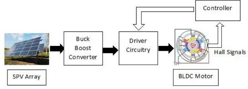
The proposed system concept is represented in its block diagram in Figure 1.
Fig. 1 Block Diagram of the Proposed System
The concept of the proposed system is to have closed loop control system of the BLDC motor. The electrical energy is generated by using solar photovoltaic array which converts energy of light into electrical energy. This signifies the adoption of renewable energy for the system. The solar photovoltaic array is followed by the Buck –Boost converter. The Buck Boost converter is a Dc-Dc converter. The output voltage magnitude of a buck-boost converter is either greater or lesser than the input voltage magnitude. The output of the buck boost converter is supplied to the driver circuitry. The driver circuitry is used BLDC motor. The Hall signals generated from the hall sensors of the motor is supplied to the controller which then controls the driver circuitry of the motor.
III.MATHEMATICAL MODELLING OF THE BLDC MOTOR
The BLDC motor is a three phase motor in which the permanent magnet mounted on the rotor and has three phase stator winding in star connection.
The modelling of the BLDC motor is carried out based on certain assumptions: 1. The motor is not saturated and should be operated with the rated current 2. The resistances of the three stator phase windings are equal.
IJEDR1903127 International Journal of Engineering Development and Research (www.ijedr.org) 736 5. Three phases are balanced one.
6. Uniform air gap.
7. Hysteresis and eddy current losses are not considered.
The model of the armature winding for the BLDC motor is expressed as follows:
[ 𝑣𝑎 𝑣𝑏 𝑣𝑐] = [
𝑅𝑠 0 0
0 𝑅𝑠 0
0 0 𝑅𝑠
] [ 𝑖𝑎 𝑖𝑏 𝑖𝑐] + 𝑑 𝑑𝑡[ 𝐿𝑎𝑎 𝐿𝑎𝑏 𝐿𝑎𝑐 𝐿𝑏𝑎 𝐿𝑏𝑏 𝐿𝑏𝑐 𝐿𝑐𝑎 𝐿𝑐𝑏 𝐿𝑐𝑐 ] [ 𝑖𝑎 𝑖𝑏 𝑖𝑐] + [ 𝑒𝑎 𝑒𝑏
𝑒𝑐] (1)
𝑣𝑎= 𝑠𝑡𝑎𝑡𝑜𝑟 𝑝ℎ𝑎𝑠𝑒 𝑣𝑜𝑙𝑡𝑎𝑔𝑒 𝑜𝑓 𝑝ℎ𝑎𝑠𝑒 𝑎 𝑣𝑏= 𝑠𝑡𝑎𝑡𝑜𝑟 𝑝ℎ𝑎𝑠𝑒 𝑣𝑜𝑙𝑡𝑎𝑔𝑒 𝑜𝑓 𝑝ℎ𝑎𝑠𝑒 𝑏 𝑣𝑐 = 𝑠𝑡𝑎𝑡𝑜𝑟 𝑝ℎ𝑎𝑠𝑒 𝑣𝑜𝑙𝑡𝑎𝑔𝑒 𝑜𝑓 𝑝ℎ𝑎𝑠𝑒 𝑐 𝑅𝑠= 𝑠𝑡𝑎𝑡𝑜𝑟 𝑟𝑒𝑠𝑖𝑠𝑡𝑎𝑛𝑐𝑒 𝑝𝑒𝑟 𝑝ℎ𝑎𝑠𝑒 𝑖𝑎= 𝑠𝑡𝑎𝑡𝑜𝑟 𝑝ℎ𝑎𝑠𝑒 𝑐𝑢𝑟𝑟𝑒𝑛𝑡 𝑜𝑓 𝑝ℎ𝑎𝑠𝑒 𝑎 𝑖𝑏= 𝑠𝑡𝑎𝑡𝑜𝑟 𝑝ℎ𝑎𝑠𝑒 𝑐𝑢𝑟𝑟𝑒𝑛𝑡 𝑜𝑓 𝑝ℎ𝑎𝑠𝑒 𝑏 𝑖𝑐= 𝑠𝑡𝑎𝑡𝑜𝑟 𝑝ℎ𝑎𝑠𝑒 𝑐𝑢𝑟𝑟𝑒𝑛𝑡 𝑜𝑓 𝑝ℎ𝑎𝑠𝑒 𝑐 𝐿𝑎𝑎= 𝑠𝑒𝑙𝑓 𝑖𝑛𝑑𝑢𝑐𝑡𝑎𝑛𝑐𝑒 𝑜𝑓 𝑝ℎ𝑎𝑠𝑒 𝑎 𝐿𝑏𝑏= 𝑠𝑒𝑙𝑓 𝑖𝑛𝑑𝑢𝑐𝑡𝑎𝑛𝑐𝑒 𝑜𝑓 𝑝ℎ𝑎𝑠𝑒 𝑏 𝐿𝑐𝑐= 𝑠𝑒𝑙𝑓 𝑖𝑛𝑑𝑢𝑐𝑡𝑎𝑛𝑐𝑒 𝑜𝑓 𝑝ℎ𝑎𝑠𝑒 𝑐 𝐿𝑎𝑏= 𝑚𝑢𝑡𝑢𝑎𝑙 𝑖𝑛𝑑𝑢𝑐𝑡𝑎𝑛𝑐𝑒 𝑏𝑒𝑡𝑤𝑒𝑒𝑛 𝑝ℎ𝑎𝑠𝑒 𝑎 𝑎𝑛𝑑 𝑝ℎ𝑎𝑠𝑒 𝑏 𝐿𝑏𝑐= 𝑚𝑢𝑡𝑢𝑎𝑙 𝑖𝑛𝑑𝑢𝑐𝑡𝑎𝑛𝑐𝑒 𝑏𝑒𝑡𝑤𝑒𝑒𝑛 𝑝ℎ𝑎𝑠𝑒 𝑏 𝑎𝑛𝑑 𝑝ℎ𝑎𝑠𝑒 𝑐 𝐿𝑐𝑎= 𝑚𝑢𝑡𝑢𝑎𝑙 𝑖𝑛𝑑𝑢𝑐𝑡𝑎𝑛𝑐𝑒 𝑏𝑒𝑡𝑤𝑒𝑒𝑛 𝑝ℎ𝑎𝑠𝑒 𝑐 𝑎𝑛𝑑 𝑝ℎ𝑎𝑠𝑒 𝑎 ea, eb, ec = phase back emf
Based on above mentioned assumptions, the self-inductances and mutual inductances is given below. 𝐿𝑎𝑎= 𝐿𝑏𝑏= 𝐿𝑐𝑐= 𝐿 (2)
𝐿𝑎𝑏= 𝐿𝑏𝑐= 𝐿𝑐𝑎= 𝐿𝑏𝑎= 𝐿𝑐𝑏= 𝐿𝑎𝑐= 𝑀 (3)
Substituting the above equations in modeling equation. [
𝑣𝑎 𝑣𝑏 𝑣𝑐] = [
𝑅𝑠 0 0
0 𝑅𝑠 0
0 0 𝑅𝑠] [ 𝑖𝑎 𝑖𝑏 𝑖𝑐] + 𝑑 𝑑𝑡[ 𝐿 𝑀 𝑀 𝑀 𝐿 𝑀 𝑀 𝑀 𝐿] [ 𝑖𝑎 𝑖𝑏 𝑖𝑐] + [ 𝑒𝑎 𝑒𝑏
𝑒𝑐] (4)
IV.CONCEPT OF FUZZY LOGIC
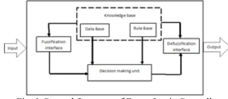
There are two types of logic: Boolean Logic and Fuzzy Logic. Boolean logic deals only with two things – true and false, 1 and 0. The Fuzzy logic allows the true, false and partial true. It functions as per the functioning of the brain providing various results.In simple terms it can be explained that if the food is tasty or not, in terms of Boolean logic it is either tasty or not tasty but in terms of Fuzzy Logic there are various options – very much tasty, tasty, less tasty and no tasty. Figure 2 shows the general architecture of the Fuzzy logic controller system. A Fuzzy logic controller comprises of four parts: Fuzzifier, Rules sets, Interface engines and Defuzzifier.
The function of the fuzzifier is to transform the crisp value into the fuzzy subsets for the formation of the membership’s degrees and represented in the linguistic variables to generate rules. The fuzzy sets is represented by its membership functions which is having different shapes based on its application. The fuzzy interface engines processed the rules for achieving desired output. The defuzzifier converts the fuzzy logic into crisp value for the fuzzy logic controller process.
IJEDR1903127 International Journal of Engineering Development and Research (www.ijedr.org) 737
Circuit Diagram and its Description
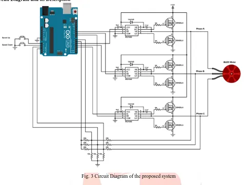
Fig. 3 Circuit Diagram of the proposed system
Figure 3 represents the circuit diagram of the system, It represent the driving circuitry of the BLDC motor, the electricity generated from the SPV array along with buck boost converter is fed to the microcontroller Atmega328. From the microcontroller, the BLDC motor is driven by the driver circuitry.
In the SPV array fed BLDC system, two push buttons are used. One is used to increase the speed of the motor and another one is used to decrease the speed of the motor. All grounded terminals are connected together.
The first three 33k (connected to motor phases) and the three 10k resistors are used as voltage dividers, because the microcontroller cannot be supplied with 12V, the other three 33k resistors generate the virtual natural point. The virtual natural point is connected to the microcontroller pin 6.
The ATmega328P microcontroller having one analog comparator. The positive input of this comparator is on microcontroller pin 6 (AIN0) and the negative input can be pin 7 (AIN1), A0 (ADC0), A1 (ADC1), A2 (ADC2), A3 (ADC3), A4 (ADC4) or A5 (ADC5). The virtual natural point is connected to the positive pin of the analog comparator (pin 6), phase A BEMF (back electromotive force) to pin 7 (AIN1), phase B BEMF to pin A2 and phase C BEMF to pin A3. Each time the comparator compares the virtual point with the BEMF of one phase (this is done in the software).
BLDC motor is a 3 phase motor. Each phase is accompanied with two N- type Mosfets, one is connected is connected on high side (+12V) and another is connected on low side (ground or 0V). The IR2104S chips are used to control high side and low side mosfets of each phase. The switching between the high side and the low side is done according to the control lines IN and SD. The Figure 4 shows input and output timing diagram:
Fig. 4 Input & Output Timing Diagram of Driver Circuit
IJEDR1903127 International Journal of Engineering Development and Research (www.ijedr.org) 738 VI.RESULTS
The driver circuit is an IR2104S IC. It is connected to each phase. It is associated with two MOSFET, one is at high side and another is at low side. The output at HO and LO depends upon the input IN and SD’. The input and output relation of IR2104S is given below.
If SD’=High (=1) then HO= IN and LO= HO’ and If SD’ = Low (=0) then HO = LO = Low (=0)
The above condition is reflected in the table 1 given below and the figure 4 is the representation of the table 1. Table 1 Input and Output of Driver circuit
Input Output
IN SD’ HO LO
0 1 0 1
1 1 1 0
1 0 0 0
0 0 0 0
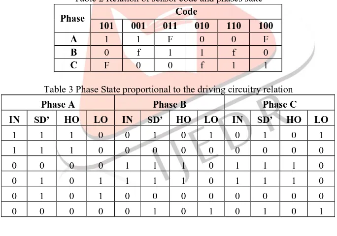
The motor rotates for 360° will result in one complete revolution. For the three phases, each phase will be supplied for 120°. With every 60° rotation, one of the Hall sensor changes its states. Each step is defined as 60° rotation of the rotor position. The hall sensor code is observed in the table 2, depending upon the coding the states of each phase is observed. For every 60° rotation, one of the Hall sensors changes its state; Hence each step is termed as 60° rotation. For each step, there is one motor terminal driven high, another motor terminal driven low, with the third one left floating. The relation between the sensor code and the states of each phase is shown in the table 2 where F is the floating state. The operating states of the BLDC motor represented in Table 2 is achieved by the input and output relation of driver for phase A, B and C respectively is represented in Table 3. The input IN and SD’ of phase A, B and C is connected to the pins of the microcontroller at Port PB and PD respectively. Accordingly, the states of each phase are observed from the Table 4. The result is achieved by using the following tables for the controlling of BLDC motor.
Table 2 Relation of sensor code and phases state
Phase Code
101 001 011 010 110 100
A 1 1 F 0 0 F
B 0 f 1 1 f 0
C F 0 0 f 1 1
Table 3 Phase State proportional to the driving circuitry relation
Phase A Phase B Phase C
IN SD’ HO LO IN SD’ HO LO IN SD’ HO LO
1 1 1 0 0 1 0 1 0 1 0 1
1 1 1 0 0 0 0 0 0 0 0 0
0 0 0 0 1 1 1 0 1 1 1 0
0 1 0 1 1 1 1 0 1 1 1 0
0 1 0 1 0 0 0 0 0 0 0 0
0 0 0 0 0 1 0 1 0 1 0 1
Table 4 Relation of sensor code and phases state along with the ports
PORT Pin Phases 1 2 3 4 5 6
PB3 11 IN
A 1 1 0 0 0 0
PD5 5 SD’ 1 1 0 1 1 0
PB2 10 IN
B 0 0 1 1 0 0
PD6 6 SD’ 1 0 1 1 0 1
PB1 9 IN
C 0 0 0 0 1 1
IJEDR1903127 International Journal of Engineering Development and Research (www.ijedr.org) 739 VII.CONCLUSION
The desired result is achieved using simple and efficient circuitry and logic. The sensored BLDC motor is used for the controlling operation. The Hall sensor is inbuilt in the motor. The further modification is achieved using the sensorless BLDC motor. There is much more improvement is needed for more efficient and smooth operation because there are some issues in the sensored BLDC motor for the functioning as the accurate position is requires for the appropriate controlling action. This concept can be implemented for the small application.
VIII.ACKNOWLEDGMENT
The complete task is cannot be completed with the guidance of the professors with their in depth related to the subject. I would like to thank them for their support and guidance for initiating this research.
REFERENCES
[1] S. Sarada, C. Ganesh and K. Aparna,” Brushless DC (BLDC) motor drive for solar photovoltaic (SPV) array fed water pumping system by using Fuzzy Logic controller”, International Journal of Electrical Engineering, ISSN 0974-2158 Volume 10, Number 3 (2017), pp. 289-305.
[2] Y. Shiva Jyothi , T. Pardhavi Sai Sree,” Brushless DC Motor Drive Based On Fuzzy Logic Controller for Solar PV Fed Water Pumping System Using Zeta Converter”, International Journal of Innovative Research in Science, Engineering and Technology, ISSN(Online): 2319-8753, Vol. 6, Issue 9, September 2017.
[3] T. R. Premila,” Solar PV Array Fed BLDC Motor using DC-DC Converter”, International Journal of Control Theory and Applications, ISSN: 0974-5572, Volume 10.
[4] Balasubramaniam S V, Rajeswari S,” BLDC MOTOR DRIVEN PV FED WATER PUMPING SYSTEM EMPLOYING CSC CONVERTER”, International Journal of Pure and Applied Mathematics, ISSN: 1314-3395 (on-line version), Volume 118 No. 20 2018, 305-311.
[5] José Carlos Gamazo-Real , Ernesto Vázquez-Sánchez and Jaime Gómez-Gil,”Position and Speed Control of Brushless DC Motors Using Sensorless Techniques and Application Trends”, sensors ISSN 1424-8220.