Okafor et al. World Journal of Engineering Research and Technology
EFFECT OF FAULT LOCATION AND LOAD INCREMENT ON
TRANSIENT STABILITY OF POWER SYSTEM
Engr Okafor Ikenna Anthony and Uka Chukwuma*
(B. Eng., M. Eng.) Department of Electrical/Electronic Technology Education Federal
College of Education (Technical) P.M.B 0189 Umunze, Anambra State Nigeria.
Article Received on 29/12/2017 Article Revised on 19/01/2018 Article Accepted on 09/02/2018
ABSTRACT
This paper is aimed at investigating the effect of some parameters on
transient stability analysis of electric power system. The analysis was
carried out using the 3-machine 9-bus Western System Coordinate
Council (WSCC) test system. The effects of parameters like fault
location and load increment were tested on the system. The result show
that when faults close to the generating station are cleared, the system
returns to stability more rapidly than those on lines further away from
the station and load increment also lead to loss of synchronism of generators, thereby the
instability of the system.
KEYWORDS: fault location; load increment; stability.
INTRODUCTION
The transient stability is one of important items in the planning and maintaining security of
power system operation. A power system at a given operating state is stable if following a
given disturbance, or a set of disturbances, the system state stays within specified bounds and
the system reaches a new stable equilibrium state within a specified period of time.
These disturbances can be faults such as: a short circuit on a transmission line, loss of a
generator, loss of a load, gain of load or loss of a portion of transmission network.[1,2]
World Journal of Engineering Research and Technology
WJERT
www.wjert.org
SJIF Impact Factor: 5.218*Corresponding Author Uka Chukwuma Department of
Electrical/Electronic
Technology Education
Federal College of
Education (Technical)
P.M.B 0189 Umunze,
Power system stability is a multifaceted problem depending upon a variety of factors, such
as: the time span that must be taken into consideration in order to assess stability/instability;
the size of the disturbance considered; the physical nature of the resulting instability.
This sudden disturbance affects the system’s performance such as large variations in generator’s rotor angles, power (real and reactive) flows, bus voltages and other system
parameters.
The transient stability limits refers to the amount of power that can be transmitted through
some point in the system with stability when the system is subjected to sever disturbance. The
transient stability limits depends on duration and location of fault, construction parameters of
the network and generators, and dynamic characteristics of loads. In this order the main
objective of this paper is to know the effects of parameters such as fault location, fault
clearing time, load increment and the effect of fault on synchronous speed in transient
stability system.
METHODOLOGY A. Stability
Power-system stability is a term applied to alternating current electric power systems,
denoting a condition in which the various synchronous machines of the system remain in
synchronism, or "in step," with each other. Readjustment of voltage angles of synchronous
machine is required because power system operating under steady load condition is
perturbed. If this condition occurs and creates an unbalance between the load and system
generation, new steady state operating condition is established with subsequent adjustment of
voltage angles. The perturbation may be in the form of major disturbance like: small load,
random load changes under normal conditions, loss of generator, fault or loss of line or both.
To establish the correct condition, fresh adjustment is needed with the new operating
condition called transient period. The major criterion of stability is to maintain synchronism
at the end of the transient period for the synchronous machines.
For stability, the system oscillations must be damped, so that, the inherent forces in the
system tends to reduce oscillations. After a disturbance, the stability problem is concerned
with the behavior of synchronous machines. The stability problem can be categorized into
steady state and transient state. The voltage behind the transient reactance is determined from
………. (1)
Where
Swing Equation
Applying the laws of mechanics to the rotational motion of a synchronous machine
Where I is the moment of inertia of the rotor system, θ is the mechanical angle of the rotor in
radians with respect to a fixed reference, and is the net torque acting on the machine.
The net torque is the accelerating (or retarding) torque given by ……… (3)
Where is the shaft mechanical torque, corrected for rotational losses, and is the
electromagnetic torque
In the steady state = 0. If we measure the angular position and velocity with respect to a
synchronously rotating reference axis instead of with respect to a stationary axis,
Equation (7) can be written as
Or
Where is the angular momentum at normal speed
The rotor mechanical dynamics are represented by the following equations
Where
H= per unit inertia constant
D= damping coefficient
Numerical integration techniques are used to solve the swing equation for multi-machine stability problems. The modified Euler’s method is used to compute machine power angles
and speeds in this research work. The real electrical power output of each machine is
computed by the following equations.
, n= 1,2………….m.
models of the generators and the system load given by the differential and algebraic equations
have been stated. These equations, together, form a complete mathematical model of the
system, which, when solved numerically, simulate the system behaviours.
SIMULATION OF RESULTS
This section presents computer simulations with the program developed in the Powerworld
software environment. The analysis has been carried out on a 3-Machine 9-Bus WSCC test
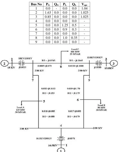
power system for an electric utility company shown in Figure 1. It consists of nine (9) buses,
tree (3) synchronous generators, three (3) loads and nine (9) transmission lines.[4,6]
Appendix
i. Generator Data
Generator H X’d
1 23.64 0.0608 2 6.4 0.1198 3 3.01 0.1813
ii. Transformer Data
Transformer Xt
1 0.0576 2 0.0625 3 0.0586
iii. Line Data
Us No. Half line charging
Admittance (p.u) Admittance(p.u.) Reactance (p.u) From Bus To Bus
1 4 0.0 0.0576 0.0
4 6 0.079 0.092 0.017
3 9 0.0 0.0586 0.0
6 9 0.179 0.17 0.039
5 7 0.153 0.161 0.032
7 8 0.0745 0.072 0.0085
2 7 0.0 0.0625 0.0
iv. Load Data
Bus No PG QG PL QL Vspc
1 0.0 - 0.0 0.0 1.04 2 1.63 0.0 0.0 0.0 1.025 3 0.85 0.0 0.0 0.0 1.025 4 0.0 0.0 0.0 0.0 - 5 0.0 0.0 1.25 0.5 - 6 0.0 0.0 0.9 0.3 - 7 0.0 0.0 0.0 0.0 - 8 0.0 0.0 1.0 0.35 - 9 0.0 0.0 0.0 0.0 -
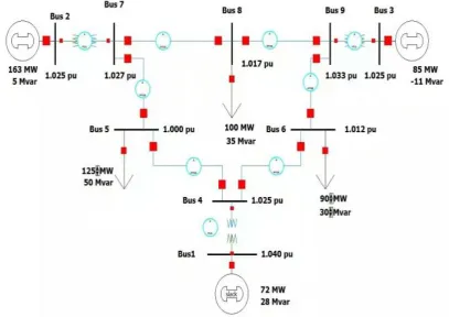
Fig. 2: 3-Machine 9-Bus WSCC test power system at run mode in Powerworld simulator.
Effect of Fault Location
This sub-section analyzes the effect of fault location in transient stability. A three-phase fault
is simulated at two different locations, one close to the generating station and the other one
far from the generating station.
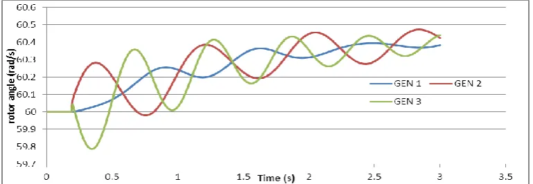
Figure 3 shows the angular positions of the generators with the generator at bus 1 as
reference, when a three phase fault occurred at bus 4 and the fault was cleared at the critical
clearing time by removal of line 4-5. The critical clearing time for this case is 232ms (see
Table 1). The generators swing together to show stable equilibrium. Figure 4 shows the
angular positions of the machines when a three phase fault occurred at bus 6 and the fault was
cleared at the critical clearing time by removal of line 4-6. The Critical clearing time for this
case is 261ms (see Table 1). The generators swing together to show stable equilibrium. It is
observed that the critical clearing time of the fault on bus 4 is lower than that of bus 6 with
reference to bus 1. This shows that when faults close to the generating station are cleared, the
Fig. 3: Rotor angle response with fault on bus 4.
Fig. 4: Rotor angle response with fault on bus 6. Effect of Load Increment
The objective of this sub-section is to investigate the impact of load increment on the Critical
Clearing Time (CCT). For this reason, active load at all buses in the 9-bus system are
increased from the base value by 10%, 20%, 30% and 40%. Real example of this case is
electrical peak load of energy consumption. In order to evaluate the effects of load variation
on the transient stability of the system, a three-phase fault was simulated at bus 1 with the
opening of line 1–4 to clear the fault. Table 2 shows the impact of the load increment on the
Critical Clearing Time. It was observed for this particular case that as the load increased
within certain range, the Critical Clearing Time decreased. Increment of the load beyond certain limit caused the machines’ rotor angle to diverge continuously leading to loss of
synchronism and hence, instability. In order to maintain the stability of the system within
certain range of the load increment, power generation has to increase while the voltage at all
buses has to drop.
Table 2: Critical clearing times with load increment.
Load increment (%) Base value 10 20 30 40
CONCLUSION
Transient Stability Analysis is a major investigation into the operation of power systems due
to the increasing stress on power system networks. The main goal of this analysis is to gather
critical information on the effect of location of fault within a power system network and
effect of load increment on the system. This information can aid protection engineer make an
informed decision when designing protection scheme for a power system. This paper presents
a transient stability analysis of a 3-Machine 9-Bus WSCC test power system using the
Powerworld software package. To analyze the effects of these parameters on the system
stability, a three-phase fault was applied at different locations in the system. The stability of
the system has been observed based on the simulation graphs of the generators’ swing curves and generators’ synchronous speed. The simulation results showed that the critical clearing
time decreases as the fault location becomes closer to the power generating station and load
increment also lead to loss of synchronism of generators, thereby the instability of the system.
The results obtained from this study, confirmed and established the findings in previous
stability studies regarding these parameters.
REFERENCES
1. Kundur, P and J. Paserba. Definition and classification of power system stability. IEEE
Trans. on Power Systems, 2004; 19(2): 1387-1401.
2. Abdul, M.M. A new method of transient stability assessment by using a simple energy
margin function. Second International Conference on Electrical and Computer
Engineering Dhaka, Bangladesh, 2002; 24–27-26-28.
3. Wang, X; S, Yonghua, and I. Malcolm, Modern Power System Analysis. Springer, New
York, USA, 2008.
4. The Illinois Center for a Smarter Electric Grid (ICSEG), "WSCC 9-Bus System," Power
Cases, [Accessed Apr. 11, 2015]. [Online]. Available:
http://publish.illinois.edu/smartergrid/wscc-9-bus-system/
5. Francisco M. Gonzalez-Longatt, "Test Case P.M. Anderson Power System," Power
Systems Test Cases, [Accessed Apr. 11, 2015]. [Online]. Available:
http://fglongatt.org/OLD/Test_Case_Anderson.html.
6. Ray D. Zimmerman, Carlos E. Murillo-Sánchez and others, "MATPOWER: A MATLAB
Power System Simulation Package," [Accessed Mar. 21, 2015]. [Online]. Available: