Author for correspondence:
1M.Tech Student, Department Of Mechanical Engineering, Holy Mary institute of technology Hyderabad, India.
2Assistant Professor, Department Of Mechanical Engineering, Holy Mary institute of technology Hyderabad, India
Volume-4 Issue-6
International Journal of Intellectual Advancements
and Research in Engineering Computations
CALCULATE MRR AND SURFACE ROUGHNESS VALUES WITH
DIFFERENT PARAMETERS BY TURNING PROCESS USING TAGUCHI
METHOD
J.Rakesh
1, P Sreenivasan
2, M Sharanya Teja
3ABSTRACT
Turning process is one of the most fundamental machining processes used in the manufacturing industry. The process of turning is influenced by many factors such as cutting velocity, feed rate, depth of cut, geometry of cutting tool, and cutting conditions etc., to name a few. In machining operations, achieving the desired surface quality of the machined product is really a challenging job. T his is due to the fact that quality is highly influenced by process parameters directly or indirectly. However, the extent of significant influence of the process parameters is different for different responses. In this work the effect of insert nose radius and machining parameters including cutting speed, feed rate and depth of cut on surface roughness and material removal rate (mrr) in a turning operation are investigated by using the Taguchi optimization method.3D modeling done by pro engineer parametric software. Analysis is done by Ansys.
Keywords: Ansys, Taguchi method, Material removal rate (MRR).
INRODUCTION
Introduction to turning
Turning is the removal of metal from the outer diameter of a rotating cylindrical work piece [1]. Turning is used to reduce the diameter of the work piece, usually to a specified dimension, and to produce a smooth finish on the metal [2]. Often the work piece will be turned so that adjacent sections have different diameters. The effects of process parameters on tool life on turning process and the subsequent optimal settings of parameters are accomplished using Taguchi`s method. Surface roughness has become the most significant technical requirement and it is an index of product quality [3]. In order to improve the tribological properties, fatigue strength, corrosion resistance
and aesthetic appeal of the product, a reasonably good surface finish is desired [5].
Chucking the Work piece
We will be working with a piece of 3/4" diameter 6061 aluminum about 2 inches long [4]. A work piece such as this which is relatively short compared to its diameter is stiff enough that we can safely turn it in the three jaw chuck without supporting the free end of the work [6].
For longer work pieces we would need to face and center drill the free end and use a dead or alive center in the tailstock to support it [7]. Without such support, the force of the tool on the work piece would cause it to bend away from the tool, producing a strangely shaped result [8, 9]. There is also the potential that the work could be forced to loosen in the chuck jaws and fly out as a dangerous projectile [10].
Fig: 1.2 Chucking the Work piece
Insert the work piece in the 3-jaw chuck and tighten down the jaws until they just start to grip the work piece. Rotate the work piece to ensure that it is seated evenly and to dislodge any chips or grit on the surface that might keep it from seating evenly. You want the work piece to be as parallel as possible with the center line of the lathe. Imagine an exaggerated example where the work piece is skewed at a angle in the chuck and you can easily visualize why this is important. Tighten the chuck using each of the three chuck key positions to ensure a tight and even grip.
EN 31 Work Tool Steel
Tool steel refers to a variety of carbon and alloy steels that are particularly well-suited to be made into tools. Their suitability comes from their distinctive hardness, resistance to abrasion, their ability to hold a cutting edge, and/or their resistance to deformation at elevated temperatures (red-hardness). Tool steel is generally used in a heat-treated state.
With carbon content between 0.7% and 1.5%, tool steels are manufactured under carefully
controlled conditions to produce the required quality. The manganese content is often kept low to minimize the possibility of cracking during water quenching. However, proper heat treating of these steels is important for adequate performance, and there are many suppliers who provide tooling blanks intended for oil quenching.
Tool steels are made to a number of grades for different applications. Choice of grade depends on, among other things, whether a keen cutting edge is necessary, as in stamping dies, or whether the tool has to withstand impact loading and service conditions encountered with such hand tools as axes, pickaxes, and quarrying implements. In general, the edge temperature under expected use is an important determinant of both composition and required heat treatment. The higher carbon grades are typically used for such applications as stamping dies, metal cutting tools, etc.Tool steels are also used for special applications like injection molding because the resistance to abrasion is an important criterion for a mold that will be used to produce hundreds of thousands of parts.
Physical Properties Metric
Density 7.81 g/cc
Mechanical Properties
Hardness, Brinell 290 - 341 Tensile Strength, Ultimate 1010 MPa Tensile Strength, Yield 800 MPa Modulus of Elasticity 205 GPa Compressive Yield Strength 850 - 1000 MPa Charpy Impact 5.02 - 10.0 J
Thermal Properties Metric
CTE,linear 12.6 µm/m-°C Specific Heat Capacity 0.460 J/g-°C
Thermal Conductivity 29.0 W/m-K
Component Elements Properties Metric
Carbon, C 0.370 % Chromium, Cr 2.0 % Manganese, Mn 1.40 % Molybdenum, Mo 0.20 % Nickel, Ni 1.0 % Silicon, Si 0.30 %
Sulfur, S <= 0.010 %
Cutting tool material - cemented
Density 14.95 g/cc
Mechanical Properties Metric
Hardness, Rockwell A 91.9
Hardness, Vickers 1575
Rupture Strength 2200 MPa
Compressive Strength 6200 MPa
Component Elements Properties Metric
Cobalt, Co 6.0 %
WC 94 %
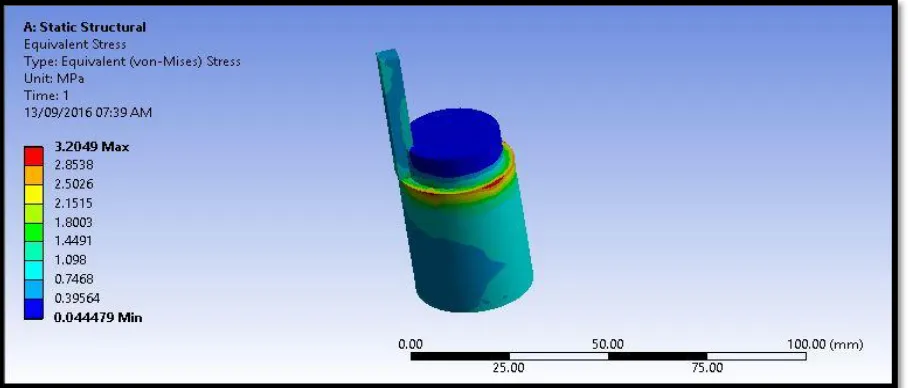
STRUCTURAL ANALYSISOF TOTAL DEFORMATION, STRESS STRAIN IN
TAGUCHI METHOD
FORCE -1150N
FIG: Total deformation, stress and strain under the force of 1150N
FORCE -992N
FIG: Total deformation, stress and strain under the force of 992N FORCE -688N
FIG: Total deformation, stress and strain under the force of 688N FORCE -550N
FIG :Total deformation, stress and strain under the force of 550N
FORCE -375N
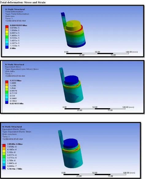
FORCE -270N
Total deformation: Stress and Strain
FIG :Total deformation, stress and strain under the force of 270N
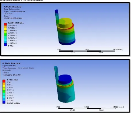
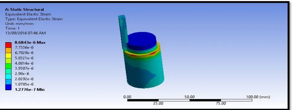
FIG : Total deformation, stress and strain under the force of 465N FORCE -297N
FIG :Total deformation, stress and strain under the force of 297N
FORCE -206N
FIG : Total deformation, stress and strain under the force of 206N
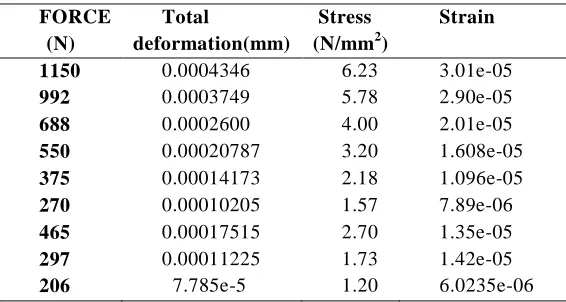
STRUCTURAL ANALYSIS RESULT TABLE
FORCE (N)
Total
deformation(mm)
Stress (N/mm2)
Strain
1150 0.0004346 6.23 3.01e-05
992 0.0003749 5.78 2.90e-05
688 0.0002600 4.00 2.01e-05
550 0.00020787 3.20 1.608e-05
375 0.00014173 2.18 1.096e-05
270 0.00010205 1.57 7.89e-06
465 0.00017515 2.70 1.35e-05
297 0.00011225 1.73 1.42e-05
EXPERIMENTAL INVESTIGATION
The experiments are done on the CNC turning machine with the following parameters:
Cutting tool material
Cemented Carbide Tool
Work piece material
EN 31Tool Steel
Feed
200mm/min, 250mm/min, 300mm/min
Cutting speed
600rpm, 1200rpm, 1800rpm, DEPTH OF CUT –
0.4mm, 0.5mm, 0.6mm
Experimental photos
FIG: CNC turning machine
FIG: CNC turnning machine feed
FIG: CNC turnning machine depth of cut
FIG: Final surface finish workpiece
FIG: Final surface finish workpiece
TABLE: Different parameters values
PROCESS PARAMETERS
LEVEL 1
LEVEL 2
LEVEL 3
CUTTING SPEED(rpm) 600 1200 1800
FEED RATE (mm/rev) 200 250 300
DEPTH OF CUT(mm) 0.4 0.5 0.6
TABLE: Input values for surface finish SURFACE FINISH
JOB NO.
SPINDLE SPEED (rpm)
FEED RATE (mm/min)
DEPTH OF CUT (mm)
2 600 250 0.5
3 600 300 0.6
4 1200 200 0.4
5 1200 250 0.5
6 1200 300 0.6
7 1800 200 0.4
8 1800 250 0.5
9 1800 300 0.6
TABLE: Total Different parameters values for surface finish
JOB NO. SPINDLE SPEED (rpm) FEED RATE (mm/min) DEPTH OF CUT (mm) Surface finish
(Ra)
1 600 200 0.4 0.62
2 600 250 0.5 0.78
3 600 300 0.6 0.91
4 1200 200 0.4 1.21
5 1200 250 0.5 1.46
6 1200 300 0.6 1.94
7 1800 200 0.4 2.41
8 1800 250 0.5 2.84
9 1800 300 0.6 3.12
RESULTS AND DISCUSSION
Cutting Force Calculations
SPEED – 1800rpm
Feed = 200mm/min, Depth of cut – 0.4mm Cutting Force
Ne = (Depth X Feed X Cutting Speed X Ks) / (60
X 103 X Coefficient of Efficiency) Ne = 4.65KW
Ks = (Ne X60 X 103 X Coefficient of Efficiency)/ (Depth of cut X Feed X Cutting Speed)
Coefficient of Efficiency = 0.8
Ks = (4.65×60 X 103 X0.8)/(0.4X200 X1800)
Ks=1150N
Feed = 250mm/min, Depth of cut – 0.5mm Ks = (4.65×60 X 103 X0.8)/(0.5X250 X1800)
Ks=992N
Feed = 300mm/min, Depth of cut – 0.6 mm Ks = (4.65×60 X 103 X0.8)/(0.6X300 X1800)
Ks=688N
SPEED – 1200rpm
Feed = 200mm/min, Depth of Cut – 0.4mm Cutting Force
Ne = (Depth X Feed X Cutting Speed X Ks) / (60
X 103 X Coefficient of Efficiency) Ne = 4.65KW
Ks = (Ne X60 X 103 X Coefficient of Efficiency)/ (Depth X Feed X Cutting Speed)
Coefficient of Efficiency = 0.8
Ks = (4.65×60 X 103 X0.8)/(0.4X200 X1200)
Ks=550N
Feed = 250mm/min, Depth of cut – 0.5mm Ks = (4.65×60 X 10
3
X0.8)/(0.5X250 X1200) Ks=375N
Feed = 300mm/min, Depth of cut – 0.6mm Ks = (4.65×60 X 103 X0.8)/(0.6X300 X1200)
Ks=270N
SPEED – 600rpm
Feed = 200mm/min, Depth of cut – 0.4mm Ks = (4.65×60 X 10
3
X0.8)/(0.4X200X600) Ks=465.2N
Feed = 250mm/min, Depth of cut – 0.5mm Ks = (4.65×60 X 103 X0.8)/(0.5X250 X600)
Ks=297.6N
Feed = 200mm/min, Depth of cut – 0.6mm Ks = (4.65×60 X 10
3
S/N ratio calcution by Taguchi Method
Taguchi method stresses the importance of studying the response variation using the signal–to– noise (S/N) ratio, resulting in minimization of
quality characteristic variation due to uncontrollable parameter. The cutting force is considered as the quality characteristic with the concept of "the smaller-the-better". The S/N ratio for the smaller-the-better is:
S/N =
Where n is the number of measurements in a trial/row, in this case, n=1 and y is the measured value in a run/row. The S/N ratio values are
calculated by taking into consideration above Eqn. with the help of software Minitab 17.
The force values measured from the experiments and their corresponding S/N ratio values are listed in Table
Analysis and Discussion
Regardless of the category of the performance characteristics, a greater S/N value corresponds to a better performance. Therefore, the optimal level of the machining parameters is the level with the greatest value.
Spindle Speed
The effect of parameters spindle speed on the surface finish is shown above figure for S/N ratio. So the optimum spindle speed is 1800 rpm.
Feed Rate
The effect of parameters feed rate on the surface finish is shown above figure S/N ratio. So the optimum feed rate 250 mm/min.
Depth of Cut
The effect of parameters depth of cut on the surface finish is shown above figure for S/N ratio. So the optimum depth of cut is 0.6mm.
CONCLUSION
In this thesis an attempt to make use of Taguchi optimization technique to optimize cutting parameters during high speed turning of EN 31 tool steel using cemented carbide cutting tool.
Cutting forces, surface finish and cutting temperatures are validated experimentally.
By observing the experimental results and by
taguchi, the following conclusions can be
made
1. To minimize the cutting forces, the optimal parameters are spindle speed – 600rpm, feed rate – 200mm/min and depth of cut – 0.4mm. 2. To get better surface finish, the optimal
parameters are spindle speed – 1800rpm, feed rate – 300mm/min and depth of cut – 0.6mm.
3. To maximize material removal rate, the optimal parameters are spindle speed – 600rpm, feed rate – 200mm/min and depth of cut – 0.6mm.
4. The effects of these parameters on the cutting forces are calculated using theoretical calculations and using the forces stresses and displacements are analyzed using Ansys. 3D modeling is done in Pro/Engineer.
5. By observing the analysis results, the stress values are less than the yield stress values.
REFERENCES
[1]. Using the Response Surface Method to Optimize the Turning Process of AISI 12L14 Steel
[2]. Optimization of Process Parameters of Turning Parts: A Taguchi Approach by Neeraj Sharma, Renu Sharma
[3]. The Effect of Tool Construction and Cutting Parameters on Surface Roughness and Vibration in Turning of AISI 1045 Steel Using Taguchi Method by Rogov Vladimir Aleksandrovich, Ghorbani Siamak [4]. Parametric investigation of turning process on mild steel aisi 1018 material by J. M. Gadhiya, P. J. Patel [5]. Evaluation and Optimization of Machining Parameter for turning of EN 8 steel by Vikas B. Magdum,
Vinayak R. Naik
[6]. Analyses of surface roughness by turning process using Taguchi method by S. Thamizhmanii, S. Saparudin, S. Hasan
[7]. Application of Taguchi Method for Optimizing Turning Process by the effects of Machining Parameters by Krishankant, Jatin Taneja, Mohit Bector, Rajesh Kumar
[8]. Multi-Objective Optimization of the Cutting Forces in Turning Operations Using the Grey -Based Taguchi Method by Yigit
[9]. Experimental investigation of Material removal rate in CNC turning using Taguchi method by Kamal, Anish and M.P.Garg