Volume-7 Issue-1
International Journal of Intellectual Advancements
and Research in Engineering Computations
Automatic railway track fault detecting using wireless network systems
Thalha NS
1, C Thamilarasi
2PG Student, Assistant Professors, Department of ECE,
Shree Venkateshwara Hi-Tech Engineering College, Gobi, Tamilnadu, India.
ABSTRACT
Automatic crack detection on train tracks is highly crucial for saf ety and labor-cost efficiency. In India, most of the commercial transport is being carried out by the railway network and therefore, any problems in the same has the capacity to induce major damage to the economy-notwithstanding the societal impact of loss of life or limb. This paper proposes a cost effective yet robust solution to the problem of fire occurrence recognition and safety, detection of obstacle on the track, railway crack detection utilizing a method that is unique in the sense that while it is simple, the idea is completely novel. The paper discusses the technical and design aspects in detail and also provides the proposed robust train safety system. The paper also presents the details of the implementation of the system utilizing simple compon ents inclusive of wireless detection of signals and crack detector assembly. The proposed scheme has been modeled for robust implementation in the Indian scenario.
Keywords: Wireless Transmission, Zigbee transreciver, Humidity and temperature measurement.
INTRODUCTION
The train system is that one proficient way to travelling one place to another place. The assessment of cost is also easy to pay for all level people. In that train security process will be easily implemented, by solving the two struggles. Because train travel has been needed more security compared to other travelling vehicle. For track damage is create more causes in the train. To avoid this one by using the vibration sensor. When train is come nearby sensor at that time sensor will be sensed. To find the damage location by using GPS. For obstacle crossing in track, means using Ultrasonic sensor to measure the distance between train and object. And certainly send the message to control station by GSM. In all action of train process is controlled by GATE operation of switch. For switch means gate is open or close however when the train is come. By using the motor to run the gate, and demonstrate the message for LCD.
Literature survey
in real time [6]. That paper realizes to check the crack fault by ultra sonic sensor. When the train is nearby track to gauge distance between them. In this not attainment accurate output in real time process [7]. Even using AdHoc network gap for station by use the zigbee for trustworthiness in security. But it has reduced the accident in moderately [8].
EXISTING SYSTEMS AND
LIMITATIONS
The Railway network is the world's biggest transport System. The Indian Railways is one of the largest railways Networks in the world.
Automatic Railway System Using Wireless Sensor Network: This paper is examination for the pivotal circumstance happens in the programmed prepare framework. In the railroad looking over in numerous mischances’s because various harm forever and furthermore our property. So this venture to execute in two approach to spare the
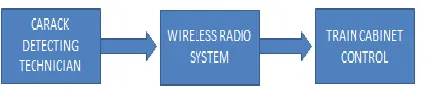
prepare travel. For the restricted is to decide the malevolent in the prepare track unremittingly, regardless of whether the track stipulation is great or not for utilize the VIBRATION Sensor to check it. Next for them to dodge the hindrance crossing in prepare track, when the prepare is come. The primary aim in this venture is to assist our railroad office with improving the programmed procedure. Additionally build up the necessity apparatuses required in that protected travel. Yet at the same time the prepare crashes happen in may put not yet diminishing one. To control the fundamental Area in prepare framework have been the entryway level operation to utilizing STEPPER MOTOR continuously investigation. This is precisely done by utilizing the PROTEUS instrument to show signs of improvement result. The current systems for railway crack detection are done manually, technicians check on the tracks by walking alongside. Cracks are marked and a following team will do the fixing. Oral communication through telephonic and telegraphic conversations.
Figure 1 Existing Bock Diagram
Limitation
Using Digital image processing, the system can be made to detect suspects whose images are previously accessible in the database is difficult to get results in fats moving train.
Simulation based controlling may not be accurate at all time results.
Slow in process control.
PROPOSED SYSTEM
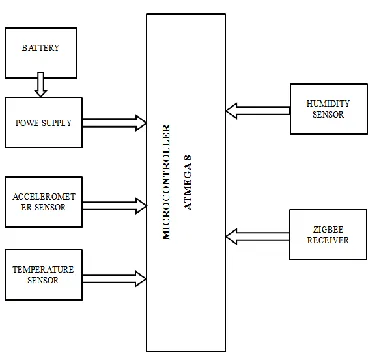
This paper deals with the idea of constructing a railway safety system that incorporates associated safety elements. Here the main command center is a microcontroller that controls and coordinates all
side zigbee receive the data and store in microcontroller also the value of temperature and
humidity sensor also fed to controller which provide the output(figure 2).
Figure 2 Transmitter Section
Figure 3 Receiver Section
The electrical schematic diagram of transmitter and receiver side as shown in figure 3.3 and figure 3.4.aZigBee coordinator or and several ZigBee end devices. The ZigBee coordinator is a full-function device (FFD) which takes carefor network formation and maintenance. The Wireless Sensor Networks include the sensor node collects the data, the root nodes as the data sink is linked to the base station, and the router node is an intermediate node to relay thedata.IR sensors use infra red light to sense objects in front of them and gauge their distance. The commonly used Sharp IR sensors have two black circles which used for this process, an emitter and a detector. Accelerometers are available that can measure acceleration in one, two, or three orthogonal axes. The familiar
metal/paper coil humidity sensor is useful for giving a dial indication of humidity changes, but it appears most often in very inexpensive devices and their accuracy is very limited.. These changes in length (analogous to those in a bimetallic thermometer) cause an indication on a dial.
Circuit Diagram
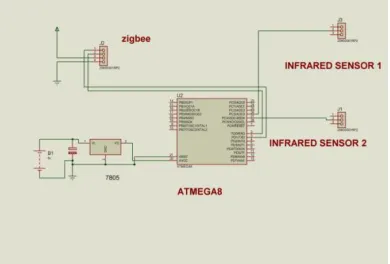
communication with other microcontroller which also connected to the serial pin by Zigbee protocol.The other pins used for Spare for our future works. The power supply must be constant so proper protection needed. The figure shows the drawing plotted on proteus software for board
etching.No need to put ocillator for clock signal as it is generating the clock internally.The connector we are using for proper electrical insulation.The power supply for Humidity,temperature and accelerometer are connected induvidually outside of microcontroller.
figure 4 Circuit Diagram transmitter side
The figure shows the drawing plotted on proteus software for board etching.No need to put ocillator for clock signal as it is generating the clock internally.The connector we are using for proper electrical insulation. Using IC 7805 used for 5v generation for power supply to the board.a battery is a collection of multiple electrochemical cells, but in popular usage battery often refers to a
single cell.. For example, a 1.5-volt AAA battery is a single 1.5-volt cell, and a 9-volt battery has six 1.5-volt cells in series. The atmega8 is used as controller which help the takes input from sensor and transmitted to receiver area through zigbee transceiver. The sensor which is used to monitor humidty vibration and crack detection.
figure 5 Circuit Diagram Receiver Side
Future scope
The future work is on transmitting the data to main station and properly monitor and data collected using IOT. By using iot, we can schedule
CONCLUSION
The idea can be enforced in large scale to facilitate higher safety standards for railway tracks in future. The proposed system can have an excellent impact on the security and maintenance of tracks. To make sure the method is simple and efficient the principle plan has been made terribly easy. Accidents occurring in railway transportation systems price an outsized range of lives. Many people die and several others get physically and mentally wounded. Accidents are the key causes for traumatic injuries. There's a need of advanced
and sturdy techniques which will solely stop these accidents along with eradicate all potentialities of their incidence. Wireless device network that continuously monitors the railway track through the sensors and observe any abnormality within the track.
Acknowledgment
We are expressing our thanks to all Faculty members and Skilled Assistants of Electronics and Communication Engineering department and my Friends who helped me in every possible way. Last but not least I thank my Parents for their moral support.
REFERENCES
[1].Cacciola M, Megali G, Pellicanμo D, Calcagno S "Rotating Electromagnetic Field for Crack Detection in Railway Tracks", PIERS ONLINE, 6(3), 2010
[2].Gao M. Y, Wang P, Cao Y, Chen R, and Cai D. J, “Design and verification of a rail-borne energy harvester for powering wireless sensor networks in the railway industry,” IEEE Trans. Intell. Transp. Syst., 18(6), 2016, 1596–1609.
[3].Gao M. Y, Wang P, Cao Y, Chen R, and Cai D. J, “A rail-borne piezoelectric transducer for energy harvesting of railway vibration,” J. Vibroeng, 18(7), 2016, 4647–4663.
[4].Greene R.J, YatesJ.R, Patterson E.A, "Rail Crack Detection: An Infrared Approach to In-service Track Monitoring", SEM Annual Conference & Exposition on Experimental and Applied Mechanics. 2006
[5].Hartman G.A Infrared Damage Detection System (IDDS) for realtime, small-scale damage monitoring, Proc. SEM Ann. Conf. on Exptl Mech., Charlotte, North Carolina. 2003
[6].QiaoJian-hua; Li Lin-sheng; Zhang Jing-gang “Design of Rail Surface Crack-detecting System Based on Linear CCD Sensor”, IEEE Int. Conf. on Networking, Sensing and Control, 2008
[7].Richard J. Greene, John R. Yates and Eann A. Patterson, "Crack detection in rail using infrared methods", Opt. Eng. 46, 051013, 2007