Design and Analysis of an IC Engine Piston
Head to Increase the Torque on Crankshaft
J.C.Jessin1, P.Maheswaran2, M.Syed Abuthahir3, K.Vijayan4
PG Student, M.E CAD/CAM, Department of Mechanical Engineering, M.A.M College of Engineering and Technology,
Trichy, Tamil Nadu, India1, 3
Associate Professor, Department of Mechanical Engineering, M.A.M College of Engineering and Technology, Trichy,
Tamil Nadu, India2, 4
ABSTRACT: The in-cylinder air motion in internal combustion engines is one of the most important factors
controlling the combustion process. Combustion efficiency of CI Engine can be increased by creating turbulence, by designing intake system, by designing combustion chamber. A good swirl promotes fast combustion to improve the efficiency. So in this present work a study about influence of air swirl in the combustion chamber upon the performance and emission of a diesel engine is presented to increase the torque on crankshaft. This intensification of the swirl is done by the cutting grooves on the crown of the piston, by three different configurations of Model A, B, C. CFD Analysis is carried out on a diesel engine using Modified different configuration piston which is a four stroke single cylinder air cooled and constant speed engine. Performance parameters such as Swirl ratio, Tumble ratio, Turbulent Kinetic Energy, Turbulent Intensity and Turbulent dissipation rate are calculated. CREO 3.0 is a parametric software used for design and Ansys IC Engine Solver 15.0 is used for analysis.
KEYWORDS: IC Engine, Piston Head, Air swirl, Turbulent, Creo 3.0, Ansys 15.0 IC Engine Solver.
I. INTRODUCTION
Internal combustion engines have been a relatively inexpensive and reliable source of power for applications ranging from domestic use to large scale industrial and transportation applications for most of the twentieth century. DI Diesel engines, having the evident benefit of a higher thermal efficiency than all other engines, have served for both light- duty and heavy-duty vehicles. The in-cylinder fluid motion in internal combustion engines is one of the most important factors controlling the combustion process. It governs the fuel-air mixing and burning rates in diesel engines. The fluid flow prior to combustion in internal combustion engines is generated during the induction process and developed during the compression stroke (Xueliang and ShuSong, 1990; and Shaoxi and Wanhua, 1990). Therefore, a better understanding of fluid motion during the induction process is critical for developing engine designs with the most desirable operating and emission characteristics (Wu Zhijun and Huang Zhen, 2001).
ISSN(Online) : 2319-8753 ISSN (Print) : 2347-6710
I
nternational
J
ournal of
I
nnovative
R
esearch in
S
cience,
E
ngineering and
T
echnology
(An ISO 3297: 2007 Certified Organization)
Vol. 5, Issue 5, May 2016
It is evident that the effect of geometry has a negligible effect on the airflow during the intake stroke and early part of the compression stroke. But when the piston moves towards Top Dead Centre (TDC), the bowl geometry has a significant effect on air flow thereby resulting in better atomization, better mixing and better combustion
II. INFLUENCE OF AIR MOTION IN COMBUSTION CHAMBER
To enhance the efficiency of an engine it is important to optimize thermal efficiency, which is obtained at the highest possible compression ratio. However, if the compression ratio is too high, there is a chance to have knock, which should be avoided at all cost. A solution for this problem is to promote rapid combustion, to reduce the time available for the self-ignition to occur (Jorge Martins et al., 2009). To promote rapid combustion, sufficient large-scale turbulence (kinetic energy) is needed at the end of the compression stroke because it will result in a better mixing process of air and fuel and it will also enhance flame development. However, too much turbulence leads to excessive heat transfer from the gases to the cylinder walls, and may create problems of flame propagation (Stone, 1989; Blair, 1999; and Lumley, 2001).
The key to efficient combustion is to have enough swirl in the combustion chamber prior to ignition. In order to provide complete combustion at a constant rate, there is common design objective of bringing sufficient air in contact with the injected fuel particles. For this purpose, the piston crown and the cylinder head are shaped to induce a swirling motion to air, while during compression piston is moving towards TDC. The production of turbulence, i.e., swirl by different means, however, is considered necessary for better fuel-air mixing. The complexities of production and the higher costs of these methods of creating turbulence are the limiting factors in their wider use. An increase in air swirl level is noted to increase the air mass of all zones. Thus at the moment when the mixture first ignites in one zone, all other zones approaching their self-ignition temperature contain more air. Increased swirl results in an increase in the initial combustion rate and hence a higher rate of pressure rise is expected (Payriet al., 1990).
The Swirl can be generated in the diesel engine by modifying three parameters in the engine, they are the cylinder head, the piston, i.e., modification of combustion chamber and the inlet manifold (Lin and Ogura, 1995). Somender Singh (2001) has invented a multi impingement wall head is located at the center of the cylinder head to enhance the swirl and squish. Somender Singh has identified a method to improve turbulence in combustion chamber by making grooves on the cylinder head, to reduce the heat losses; the burn time needs to be as quick as possible. According to Ammar Al-Rousan (2008) swirl is generated in the inlet manifold by inserting a loop inside the intake manifolds to increase the swirling in the air during induction. Rasul and Glasgow (2005) prepared a convergent-divergent induction nozzle and is tested in order to increase the airflow into the engine, which may increase the overall performance. Prasad et al. (2011a and 2011b) and Prasad and Pandurangadu (2013) experimentally investigation on influence of the air swirl in the cylinder upon the performance and emission of a single cylinder diesel direct injection engine is presented. In order to achieve the different swirl intensities in the cylinder, three design parameters have been changed the cylinder head, piston crown, and inlet duct.
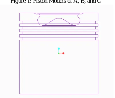
III. COMBUSTION SECTOR METHOD IN ANSYS CFD SOFTWARE
Figure 1: Piston Models of A, B, and C
ISSN(Online) : 2319-8753 ISSN (Print) : 2347-6710
I
nternational
J
ournal of
I
nnovative
R
esearch in
S
cience,
E
ngineering and
T
echnology
(An ISO 3297: 2007 Certified Organization)
Vol. 5, Issue 5, May 2016
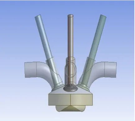
Figure 5: CFD Sector method geometry for model C
IV. SPECIFICATION OF THE ENGINE USED FOR ANALYSIS IN ANSYS IC ENGINE SOLVER
Analyzing type = ICE (Sector Type CFD Solver) Engine Type = Diesel Engine
Number of Crank angle run = 100 RPM = 1500
Connecting rod length = 320 Crank radius = 40
Minimum lift = 0.2 IVC = 570 EVO = 833
Minimum Spray length = 0.02 Spray angle = 70 degree Combustion Mixture O2 = 0.232
CO2 = 0.00046 H2O = 5e-7
Total flow rate = 0.10 kg/sec (100 cc)
Figure 6: CFD analysis for model A at 740 degree Figure 7: CFD analysis for model B at 740 degree
crank angle crank angle
Figure 8: CFD analysis for model C at 740 degree crank angle
0 0.5 1 1.5
C
ra
n
k
An
gl
e
5
6
0
5
7
0
5
8
0
6
0
0
6
2
0
6
4
0
6
6
0
6
8
0
7
0
0
7
2
0
7
4
0
7
6
0
7
8
0
8
0
0
8
2
0
ISSN(Online) : 2319-8753 ISSN (Print) : 2347-6710
I
nternational
J
ournal of
I
nnovative
R
esearch in
S
cience,
E
ngineering and
T
echnology
(An ISO 3297: 2007 Certified Organization)
Vol. 5, Issue 5, May 2016
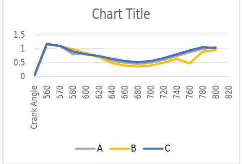
Figure 10: Turbulent Intensity
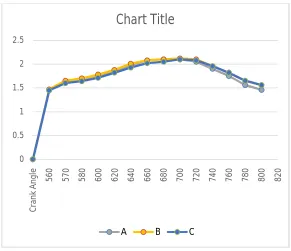
Figure 11: Turbulent Dissipation Rate
0 200 400 600 800 1000 1200 1400 1600 1800 2000 C ra n k An gl e 5 6 0 5 7 0 5 8 0 6 0 0 6 2 0 6 4 0 6 6 0 6 8 0 7 0 0 7 2 0 7 4 0 7 6 0 7 8 0 8 0 0 8 2 0
Chart Title
A B C
0 0.5 1 1.5 2 2.5 C ra n k An gl e 5 6 0 5 7 0 5 8 0 6 0 0 6 2 0 6 4 0 6 6 0 6 8 0 7 0 0 7 2 0 7 4 0 7 6 0 7 8 0 8 0 0 8 2 0
Chart Title
V.RESULT
The results for the modified piston are taken from the Computational Fluid Analysis. The calculated swirl ratio is 1.3. The results are taken and compare between the three pistons for the comparison to get the better modified model. Combustion Sector method is done in IC Engine Solver Ansys Software. From the CFD result we assure that the model C is efficient than other two models. The turbulent is lightly increased compared to model A and B. Due to this, we can get the complete burning of the fuel during the combustion operation in IC Engine Piston. Normally Fuel burning ratio is between 70 to 80 percentages. We got 81.23 % for model A, 72.87% for model B and 83.61% for model C. Model C have good fuel burning efficiency.
Due to the burning efficiency, there is a high combustion rate in the internal Combustion Engine. When the combustion is increased, the speed of the piston stroke is increased which results in increase of torque on crankshaft. So the modified model of Model C consider as good and efficient model but the solution also want to justify practically to justify. In this paper, CFD based experiments are concentrated.
REFERENCES
[1] ANALYSIS OF A SINGLE CYLINDER COMBUSTION ENGINEUSING CFD G.SureshBabu,S.D.V.S.Jagadeesh, U.B.Saicharan, P.R.S.Praneeth
[2] COMBUSTION ANALYSIS OF INVERTED M TYPE PISTON CI ENGINE BY USING CFD
Dr. Hiregoudar, ManjunathaK, Kumar K JProfessor and PG Co-ordinator Mechanical Engineering Department, RYMEC Bellary, Karnataka,
[3] ENHANCEMENT OF AIR SWIRL IN A DIESEL ENGINE WITH GROOVED CYLINDER HEAD
Dr.S.L.V. Prasad, Prof V.Pandurangadu, Dr.P.Manoj Kumar, Dr G. Naga Malleshwara Rao Dept. of Mechanical Engineering, Shri ShiridiSai Institute of Science and Engg. Anantapur, A.P India
[4] A REVIEW ON STUDY OF THE EFFECT OF IN CYLINDER AIR SWIRL ON DIESEL ENGINE PERFORMANCE AND EMISSION
SanthoshKumar.G, Prof.K.Hema Chandra Reddy, Ch.Rajesh, G.Suresh Kumar
[5] FAILURE OF PISTON IN IC ENGINES: A Review R. C. Singh, Roop. Lal, Ranganath M S, Rajiv Chaudhary
[6] EXPERIMENTAL INVESTIGATION OF A SINGLE CYLINDER 4- STROKE DI DIESEL ENGINE BY SWIRL INDUCTION WITH TWO DIFFERENT CONFIGURATION PISTONS