Darshan et al. World Journal of Engineering Research and Technology
A COMPACT DEFECTED GROUND OCTAGONAL SHAPED PATCH
ANTENNA FOR UWB APPLICATIONS
Darshan Sati,* Naval Kishor Chaudhary and Vijaya Bhandari
Department of Electronics & Communication Engineering Bipin Tripathi Kumaon Institute
of Technology Dwarahat Almora 263653, Uttarakhand India.
Article Received on 16/03/2016 Article Revised on 04/04/2016 Article Accepted on 24/04/2016
ABSTRACT
A compact defected ground octagonal shaped patch antenna is
presented. The antenna uses duroid (εr= 2.2) as a substrate. The
ultra-wideband (UWB) range is covered using octagonal stub and
rectangular slot. Octagonal stub is used for impedance matching. The
stub and rectangular slot shows a good coupling in the entire UWB
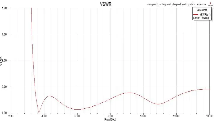
range. The designed antenna provides a wide bandwidth which ranges
from 3.5 to 13.2 GHz (9.7 GHz) with VSWR less than 2. A thorough
study of radiation characteristics of the antenna is presented. The proposed antenna has a
small size of 22×24×1.6 mm3 while sustaining the UWB performance.
KEYWORDS: Compact antenna, defected ground, patch antenna, ultra wideband (UWB).
INTRODUCTION
In recent wireless communication systems, antennas are required which are compact in size,
simple in structure and stable in gain and radiation characteristics while holding an
enormously wide operating frequency range. In 2002, the Federal Communication
Commission (FCC) allocated the spectrum from 3.1 to 10.6 GHz for unlicensed UWB
measurements and communication applications with EIRP less than -41.3 dBm/MHz.[1] Since
then ultra wide band (UWB) antennas have fascinated the research scholars both in
academics and industries. Ultra wide band technology overtakes existing wireless standards
World Journal of Engineering Research and Technology
WJERT
www.wjert.org
SJIF Impact Factor: 3.419*Corresponding Author Darshan Sati
Department of Electronics
and Communication
Engineering Bipin Tripathi
Kumaon Institute of
Technology Dwarahat
Almora 263653,
such as Bluetooth PANs and 802.11 LANs with the competency to handle multiple high data
rate streams at lower consumed power in simple, compact transceiver architecture.[2]
Fig.1. Geometry of the proposed antenna.
The microstrip ultra wideband (UWB) antennas have enticed much attention owing to their
advantages such as simple structure, high data rate, low profile, easy integration with
monolithic microwave integrated circuits (MMICs) and ease of fabrication. However the
design of a wideband antenna is not an easy task particularly for a portable device because a
trade-off between the size, cost and bandwidth has to be accomplished simultaneously.
Various shapes of printed slot antennas have been presented in open literature.[3]-[7] including tapered shape slot antenna, semi elliptical monopole, open slot antenna with bandwidth
enhancing and a printed wide slot antenna with a rotated slot.
In this communication a compact defected ground octagonal shaped patch antenna is
proposed. The measured impedance bandwidth of the proposed antenna is 9.7 GHz from 3.5
to 12 GHz (defined by -10 dB return loss). In addition, the proposed antenna has a simple
structure and a small size i.e. 22×24×1.6 mm3. The designed antenna has been simulated using High Frequency Structure Simulator (HFSS) 14.0.
ANTENNA CONFIGURATION AND DESIGN
Antenna 1 Proposed Antenna
(a) (b)
The geometry of the proposed octagonal shaped slot antenna is shown in the Fig.1. The
proposed antenna is composed of four parts: 1) octagonal patch, 2) substrate i.e. duroid (εr =
2.2, tanδ =0.01), 3) rectangular slotted ground, 4) microstrip feed. The dimensions of the
substrate are 22×24×1.6 mm3 (L1×W1×h). The proposed antenna has a rectangular stub on the
top side of the substrate which is fed by a 50-Ω microstrip line of width 3 mm and length 6
mm. This is optimised size of the feed to achieve a miniaturized design.
The rectangular slot in the ground plane shows strong coupling to the feeding structure.
Therefore, by properly selecting the slot shape and tuning stub, good impedance bandwidth
and radiation characteristics can be achieved. All parameters of the antenna are simulated
using the Ansoft HFSS 14.0 commercial software. The optimized parameters of the proposed
antenna are mentioned in the Table 1.
It initiates with the design of antenna 1, which consists of a straight microstrip feed line, a
rectangular patch and a rectangular slotted ground as shown in Fig. 2. The antenna 1 gets two
impedance bandwidths with -10 dB return loss (3.9-7.8 GHz) and (10-14 GHz). However it
can’t satisfy the requirement of UWB applications. It is worth stating that when the rectangular patch of the antenna is fed by a 50 Ω microstrip line multiple resonances can be
generated, however, impedance matching of the antenna is poor.
Table 1: Design parameters of the proposed compact microstrip fed defected ground
octagonal shaped patch antenna shown in Fig.1.
Parameters L1 L2 L3 W1 W2 W3 W4
Unit (mm) 22 18 3 24 9.75 2.5 6
To enhance the impedance matching of the proposed antenna an octagonal patch is connected
to the straight microstrip line. The proposed antenna could get an ultra-wide impedance
bandwidth with good impedance matching after cutting rectangular slot on the ground and
octagonal shaped patch with side 2.5 mm. Using octagonal patch a wide band impedance
characteristics (3.5-13.2 GHz) is obtained.
VARIATION OF SLOT SIZE WIDTH
Fig.3 shows the results of the proposed antenna with width of slot (W2) ranges from 9 to 10
mm (step size of 0.25 mm). Usually a large slot is used in a UWB antenna to achieve a high
level of electromagnetic coupling to the tuning stub. It can be realized that the S11 < -10 dB
increase in W2 decreases the bandwidth. Hence, W2 = 9.75 is chosen as optimum slot width
covering 3.5 to 13.2 GHz.
Fig. 3. Effects of varying slot width W2
EFFECT OF PATCH SHAPE
Variation of the tuning stub shape and slot shape will change the coupling and hence, control
the impedance matching. In order to optimize coupling between microstrip line and slotted
ground, rectangular patch is replaced by octagonal patch. Fig.4 shows the return loss (S11)
parameter for both patch shapes.
RESULTS AND DISCUSSION
The proposed antenna is simulated using the Ansoft HFSS 14.0. Fig.5 shows the simulated
return losses of the proposed antenna. From the simulated result, a wide operating bandwidth
from 3.5 to 13.2 GHz with -10 dB return loss has been obtained. It can be perceived that the
proposed antenna could produce three resonant frequencies (3.68, 6.02 and 10.88 GHz)
covering the UWB band. The VSWR curve for the proposed antenna is shown in the Fig.6.
The width of the slot W2 affects impedance bandwidth of the proposed antenna. Fig.3 shows
the simulated return loss curves for different values of W2 keeping all other parameters same
as in proposed design. W2 = 9.75 mm gives the optimum results. The gap (h) between patch
and ground plays a significant role in impedance matching. It is observed that h=1.6 mm is
optimum value which provides best results.
Fig. 5. Simulated return loss of the proposed antenna.
The simulated radiation patterns at 3.68, 6.02 and 10.88 GHz are plotted in the Fig.7. From
the point of view of the results, the proposed antenna displays nearly omnidirectional
radiation patterns. It is worth mentioning that the antenna has an overall size of 22×24×1.6
mm3 which is one of the smallest UWB microstrip antennas.
(a)
(b)
(c)
Fig. 7. Radiation pattern for various resonance frequencies for the proposed antenna (a)
CONCLUSION
A compact defected ground octagonal shaped patch antenna for UWB applications is
proposed. The simulated results of the antenna show stable radiation patterns over UWB band
as well as extra bands. The good impedance matching characteristic and omnidirectional
radiation patterns over the entire operating bandwidth of 3.5 to 13.2 GHz (9.7 GHz) make
this antenna a suitable candidate for UWB applications and systems.
REFERENCES
1. “Revision of part 15 of the commission’s rules regarding ultra-wideband transmission
systems first report and order FCC 02. V48,” tech. rep., FCC, Washington, DC, 2002.
2. M. Gopikrishna, Deepti Das Krishna, C. K. Anandan, P. Mohanan and K. Vasudevan,
”Design of a Compact Semi-Elliptic Monopole Slot Antenna for UWB Systems,” IEEE
Transactions on Antennas and Propagation, June 2009; 57(6).
3. Anil Kr Gautam, Member, IEEE, Swati Yadav and Binod Kr Kanaujia, Member, IEEE,
“A CPW Fed Compact UWB Microstrip Antenna,” IEEE Antenna and Wireless
Propagation Letters, 2013; 12: 151-154.
4. R. Azim, M. T. Islam and N. Misran, “Compact tapered shape slot antenna for UWB
applications,” IEEE Antenna and Wireless Propagation Letters, 2011; 10: 1190–1193.
5. WeiXing Liu, YinZeng Yin, WenLong Xu and ShaoLi Zuo,” Compact open-slot antenna
with bandwidth enhancement,” IEEE Antennas and Wireless Propagation Letters, 2011;
10.
6. J.-Y. Jan and J.-W. Su, “Bandwidth enhancement of a printed wide-slot antenna with a
rotated slot,” IEEE Trans. Antennas Propag., Jun. 2005; 53(6): 2111–2114.
7. Z.-A. Zheng, Q.-X. Chu and Z.-H. Tu, “Compact band-rejected ultrawideband slot
antennas inserting with and resonators,” IEEE Trans. Antennas Propag., Feb. 2011; 59(2):