Experimentation for Packet Loss on MSP430 and
nRF24L01 Based Wireless Sensor Network
S. S. Sonavane, Dr. B. P. Patil
Department of Electronics Engineering,Maharashtra Academy of Engineering, Alandi (Pune), State-Maharashtra (India) Email: [email protected], [email protected]
Dr. V. Kumar
Department of Electronics & Instrumentation Engineering,
Indian School of Mines University, Dhanbad-826004, State-Jharkhand (India) Email: [email protected]
---
ABSTRACT---
In this paper, a new design of wireless sensor network (WSN) node is discussed which is based on components with ultra low power. We have developed a Low cost and low power WSN Node using MSP430 and nRF24L01. The architectural circuit details are presented. This architecture fulfils the requirements like low cost, low power, compact size and self-organization. Various tests are carried out to test the performance of the nRF24L01 module. The packet loss, free Space loss (FSL) and battery lifetime calculations are described. These test results will help the researchers to build new applications using above node and to work efficiently with nRF24L01.
Keywords: Wireless Sensor Networks, MSP430, nRF24L01, Free Space Loss, battery lifetime, packet loss.
---
Paper submitted: 24.02.2009 Accepted: 25.05.2009
---
1. INTRODUCTION
A
wireless sensor network is a network made up of hundreds or thousands of Sensor nodes which are densely deployed in an unattended environment [1]. These nodes are capable of communicating by means of wireless communications, sensing and self-computation (software, hardware, algorithms). Hence the wireless sensor network is the result of the combination of sensor, embedded techniques, distributed information processing, and communication mechanisms. The sensor network is more application specific than traditional networks designed to accommodate various applications [2,3,4]. The organization and architecture of a sensor network should be designed or adapted to suit a special task so as to optimize the system performance, maximize the operation lifetime and minimize the cost.The WSN node consists of three components i.e. microcontroller, RF module, sensor and battery [5]. As the nodes are placed in remote places the battery lifetime plays a vital role. Hence to reduce the power consumption, we use ultra low power consumption based components. Also the duty cycle is kept < 1% so that the on time is reduced [6]. To test the performance of radio, we had carried out tests for packet loss, free Space loss (FSL) and battery lifetime.
The paper is organized as: section II describes the design of WSN node. The section III describes the test setup and procedure for packet loss, free Space loss (FSL) and battery lifetime calculations and the corresponding graphs are explained. Section IV concludes the paper.
2. DESIGN OF ULTRA LOW POWER WSN NODE
The Fig.1 shows WSN node with following components:
Fig.1 Front side of WSN Node with MSP430 and nRF24L01
This Node features MSP430F1612, ultra low power microcontroller having the lowest power consumptions and fastest wake-up cycles. The Texas Instruments MSP430 family of ultra low-power microcontrollers consists of several devices featuring different sets of peripherals targeted for various applications. The architecture, combined with five low power modes is optimized to achieve extended battery life in portable measurement applications. The device features a powerful 16-bit RISC CPU, 16-bit registers, and constant generators that attribute to maximum code efficiency [7-8].
The digitally controlled oscillator (DCO) allows wake-up from low-power modes to active mode in less than 6µs and may operate up to 8MHz. Typically, the DCO will turn on from sleep mode in 300ns at room temperature. The MSP430F1612 has two built-in 16-bit timers, a fast 12-bit A/D converter, dual 12-bit D/A converters, one or two universal serial synchronous/ asynchronous communication interfaces (USART), I2C, DMA, and 48 I/O pins. The core module also has a 4 Mbit flash chip that can be used for storing several firmware images or for logging data.
2.2 The nRF24L01 RF Module
The nRF24L01 is a single chip radio transceiver for the global, license-free 2.4 GHz ISM band [9]. The low cost nRF24L01 is designed to merge very high speed communications (up to 2Mbit/s) with extremely low power (the RX current is just 12.5mA). The transceiver consists of a fully integrated frequency synthesizer, a power amplifier, crystal oscillator, demodulator, modulator and Enhanced ShockBurst protocol engine. In addition, the nRF24L01 also offers an innovative on-chip hardware solution called ‘MultiCeiver’ that can support up to six simultaneously communicating wireless devices. This makes it ideal for building wireless Personal Area Networks in a wide range of applications.
Output power, frequency channels, and protocol set-up are easily programmable through an SPI-bus. Current consumption is very low, only 8.5mA at an output power of -6dBm and 12.5mA in RX mode. Built-in modes such as Power Down (400nA current) and Standby (32µA at 130µs wakeup), makes significant power savings easily realizable. The data rate can be chosen between 1 and 2Mbit/s. This allows for short time-on-air and therefore low power consumption.
2.3 Nordic and MSP430 Connections
The nRF24L01 is a single chip 2.4 GHz Transceiver. Nordic transceiver has total nine external connectors in which six are connected to the MSP430. The nRF24L01 is interfaced with MSP430 using SPI (Serial Peripheral interface) at port3 and
synchronization between two has been achieved by MCLK (Master clock).
SPI specifies four signals: clock (SCLK), master data output slave data input (MOSI), master data input slave data output (MISO) and slave select (CSS). SCLK is generated by the master and input to all slaves. MOSI carries data from master to slave. MISO carries data from slave back to master. A slave device is selected when the master asserts its CSS signal.
2.4 Transmitted Packet format
The nRF24L01 is configured and operated through a Serial Peripheral Interface (SPI.) Through this interface the register map is available. The register map contains all configuration registers in the nRF24L01 and is accessible in all operation modes of the chip. The transmitted packet is shown in Fig. 2.
Fig.2 Transmitted Packet Format of nRF24L01
The embedded baseband protocol engine (Enhanced ShockBurst) is based on packet communication and supports various modes from manual operation to advanced autonomous protocol operation. Internal FIFOs (First In First out) ensure a smooth data flow between the radio front end and the system’s MCU. Enhanced ShockBurst reduces system cost by handling all the high-speed link layer operations.
The radio front end uses GFSK (Gaussian frequency Shift Keying) modulation. It has user configurable parameters like frequency channel, output power and air data rate. The air data rate supported by the nRF24L01 is configurable to 2Mbps. The high air data rate is combined with two power saving modes which makes the nRF24L01 very suitable for ultra low power designs. Internal voltage regulators ensure a high Power Supply Rejection Ratio and a wide power supply range.In power down mode nRF24L01 is disabled with minimal current consumption.
be activated. Power down mode is entered by setting the PWR_UP bit in the CONFIG register low. By setting the PWR_UP bit in the CONFIG register to 1, the device enters standby-I mode. Standby-I mode is used to minimize average current consumption while maintaining short start up times. In this mode part of the crystal oscillator is active. This is the mode the nRF24L01 returns to from TX or RX mode when CEis set low.
Enhanced ShockBurst is a packet based data link layer. It features automatic packet assembly and timing, automatic acknowledgement and retransmissions of packets. Enhanced ShockBurst enables the implementation of ultra low power, high performance communication with low cost host microcontrollers. The features enable significant improvements of power efficiency for bi-directional and unidirectional systems, without adding complexity on the host controller side. The main features of Enhanced ShockBurst are:
1 to 32 bytes dynamic payload length
Automatic packet handling
Auto packet transaction handling
Auto Acknowledgement
Auto retransmission
6 data pipe MultiCeiver for 1:6 star networks
3. TESTING DETAILS 3.1 To measure Packet Loss:
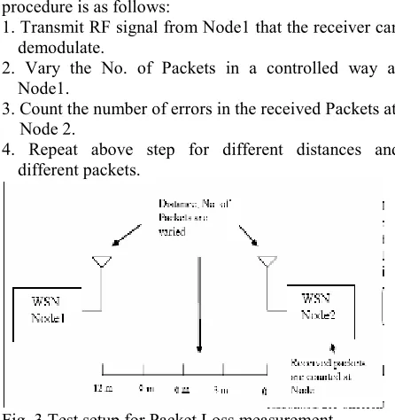
The test setup for a packet loss measurement is shown in Fig 3. We transmit desired no. of packets from Node1. At node 2 we count the received Packets to determine the Packet Error Rate (PER). The procedure is as follows:
1. Transmit RF signal from Node1 that the receiver can demodulate.
2. Vary the No. of Packets in a controlled way at Node1.
3. Count the number of errors in the received Packets at Node 2.
4. Repeat above step for different distances and different packets.
Fig. 3 Test setup for Packet Loss measurement
When conducting Packet loss measurements the receiver is tested on its performance limit. Low signal levels make this test the most demanding of all
RF prototype tests. It is very important to control the test environment closely as any additional noise directly affects the measurement. So place the WSN Node under test into the area with good line of sight.
Fig.4 Graph of BER Vs PER for different packet size
For Packet loss measurements we program the node to transmit the packets from 100 packets to 5000 packets shown in Fig 4. The packets are formed with the format as explained in Fig.2. These packets are having known payload. Hence at receiver these payloads are compared with the known data and the packet bit error rate can be calculated. The graph of BER Vs PER is shown Fig.5.
Fig.5 Graph of BER Vs PER
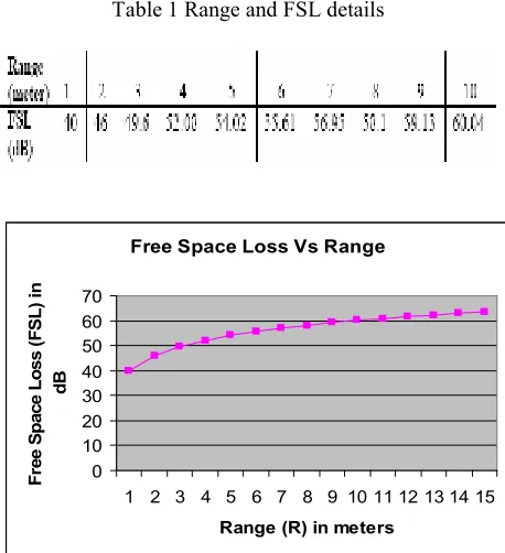
3.2 Calculation of FSL from Range:-
With ¼ wave PCB whip antenna gain of 5 to -10 dB you can achieve an effective radiated power (ERP) from the transmitters of < –5dBm @ 0 dBm Transmitter (TX) output power and a receiver sensitivity of > –75 dBm. In other words the free space loss (FSL) in the system is < 70 dB.
Free space loss (FSL) is given by: λ FSL = - 20 Log
4 π R
Where λ is the wavelength at 2.4 GHz and R is the maximum theoretical line of sight range obtainable in meters. The FSL is calculated for different range according to the above formula as given in Table 1. The
BER versus PER
(optained with different power levels )
100.0 100 packets 300 packets
Measured BER and PER (BER search)
0.0 5.0 10.0 15.0 20.0 25.0 30.0
0.00 0.02 0.04 0.06 0.08 0.10 0.12
BER [%]
P
E
R
[
%
]
Fig 6 shows graph of Range Vs FSL in which the FSL increases with distance logarithmically.
Table 1 Range and FSL details
Free Space Loss Vs Range
0 10 20 30 40 50 60 70
1 2 3 4 5 6 7 8 9 10 11 12 13 14 15
Range (R) in meters
F
re
e
S
p
a
c
e
L
o
s
s
(
F
S
L
)
in
d
B
Fig. 6 Graph of range Vs FSL
3.3 Battery Life calculations
Choosing the right battery can determine the success or failure of a wireless sensor networking project. We select the Primary lithium-thionyl chloride (Li-SOCl2) LST 14500 for our node [10]. The benefits
of this battery areHigh voltage response, stable during most of the lifetime of the application, easy integration in compact system, Non-flammable electrolyte, Low self-discharge rate (less than 1% after 1 year of storage at + 20°C) and Underwriters Laboratories (UL) Component Recognition (File Number MH 12802) . The rating is 2450 mAh.
So the battery life can be calculated by taking into account the parameter like the current consumptions of MSP430 and nRf24L01. Table 2 shows the details of battery lifetime. The duty cycle also decides the wakeup and sleep modes of MSP430 and nRF24L01. The Nordic has settings for four different power levels through PWR_UP register. The Fig. 7 shows that at low power levels the battery life will be more.
Table 2 Calculation of Battery lifetime for our WSN Node
Current Consumption and Battery life
0 2 4 6 8 10 12
1 2 3 4
Current Consumption in mA
Battery Life in Years
Fig. 7 Graph of Current Consumption and battery Lifetime
4. CONCLUSION
The hardware designed is a low power solution for WSN as compared to other commercially available motes. The test result shows that the design is having the packet loss about 0.1 %. The packet loss increases with the transmission range. The battery lifetime is also dependent on the power setting at transmitter. Hence in applications if the nodes are close to each other, use
Parameter Settings Unit
Overhead 65 bits
Payload length 8 bits
Packet length 73 bits
Bit rate 2000000 bits/s
Time on air 0.3 s
Time in RX 0.00003252 s
MCU+TX Current 11.6 mA
MCU+RX current 12.9 mA
PLL- Lock time 0.00013 s
PLL- Lock TX current 8 mA
PLL- Lock RX current 8.4 mA
Power_Dn current 0.0009 mA
Duty-cycle period 55.7 s
Power_up current 0.285 mA
Power_up time 0.0015 s
I(avg) 0.06342619 mA
Battery Used 2450 mAh
Lifetime 38627.5768 h
low power level (i.e. -18 dBm). This will enhance the battery lifetime.
This ultra low power design can be effectively adopted for applications such as environmental monitoring, home automation, Car park management system etc.
REFERENCES
[1] I. Akyildiz, W. Su, Y. Sankarasubramaniam and E. Cayirci, ‘A survey on Sensor Networks’, IEEE Communications Magazine, vol. 40, Issue: 8, pp. 102-114, August 2002.
[2]E. Lubrin, E. Lawrence, A. Zmijewska, K.F Navarro, G. Culjak, “Exploring the Benefits of Using Motes to Monitor Health: An Acceptance Survey”, Networking, International Conference on Systems and International Conference on Mobile Communications and Learning Technologies, (ICN/ICONS/MCL), on 23-29 April 2006 Page(s):202 – 208.
[3] Vanessa W.S. Tang, Yuan Zheng and Jiannong Cao, “An Intelligent Car Park Management System based on Wireless Sensor Networks”, 1st International Symposium on Pervasive Computing and Applications, 2006.
[4] Zhenwei Yu, “A Framework of Machine Learning Based Intrusion Detection for Wireless Sensor Networks”, IEEE International Conference on Sensor Networks, Ubiquitous, and Trustworthy Computing 2008.
[5] Henri Dubois, Ferri`ere Roger, Meier Laurent Fabre, Pierre Metrailler, “TinyNode: A Comprehensive Platform for Wireless Sensor Network Applications”, IPSN’06, April 19–21, 2006, Nashville, Tennessee, USA.
[6] Mohammad Ilyas and Imad Mahgoub, “Handbook of Sensor Networks: compact wireless and Wired Sensing Systems”, CRC Press, New York, 2005. [7] http://www.ti.com/msp430/datasheet accessed on
20th January 2008.
[8] S. S. Sonavane, V. Kumar and B. P. Patil, ‘Design Factors, Requirements and Research Issues for Wireless Sensor Networks’, International Journal
on Engineering Research and Industrial Applications (IJERIA), Vol-.I, No.3/ 4, June 2008. [9] http://www.nordicsemiconductor.com/nrf24L01. [10] http://csulwp.diytrade.com/sdp/679235/4/pd-3530702/3892551-1528516.html
Authors Biography
Sonavane S. S. is currently pursuing his Ph.D. from Indian School of mines, Dhanbad. He is currently working as
Professor in Dept. of Electronics Engineering at Maharashtra Academy of
Engineering, Alandi, Pune. He has published around 26 papers in International and National Journals and Conferences. His area of research includes Wireless sensor network and wireless communication.
Dr. V. Kumar received Ph.D in 1980 and worked as Scientist in CMRI, Dhanbad and Visiting Scientist at CNR, Frascati, Roma, Italy during 1983-84. He has attended number of International Conferences including conferences held in USA, Portugal, Singapore and Italy. At present, he is Associate Professor and Head of Electronic & Instrumentation Department, ISM University, Dhanbad. He has published over 100-research papers; guided 2-Ph.D. and number of M. Tech students in the areas of Opto-electronic materials and Optical Fiber Sensors.