Object Identification for Pure Object Oriented Cross
Languages Software Development
Sonar Sanjay Bhagwan
Ph.D Scholar, Rai UniversitySaroda, Dholka Taluka Ahmedabad, Gujarat, India
Samrat O. Khanna
, Ph.D Professor and Head of ISTARSardar Patel University V.V. Nagar-Anand-Gujarat,
India
Karishma D. Pasawala
Ph.D Scholar, Rai UniversitySaroda, Dholka Taluka Ahmedabad, Gujarat, India
ABSTRACT
Identifying generic or common objects is the most intricate part for developing applications in pure object oriented cross languages. Genericity or commonness in Object identification is an iterative process, and there is no appropriate formula or model to identify objects. It relies on the requirement engineering and domain engineering inception. Generic Object is a foundation of the pure object oriented software design; it is the run time automated entity. Using this paper we provide the infrastructure for identify generic objects. We design the step-to-next sequential tasks and tools in the infrastructure for Object identification. The basic tasks, tools and approaches are the infrastructure to identify generic/common System Objects. The two basic tasks are requirement engineering and domain engineering. Here Requirements engineering is based on the business model, same Domain is engineered by the requirement design, and in addition, the base domain is engineered by the domain foresting (sub-domain) rules, for objects extraction using step-to-next sequential tasks from the each foresting domain by applying the Object Identification tools.
General Terms
Generic object identification, Step-to-next sequential tasks, task assertion and O.I Tools for Object Identification
Keywords
Domain, Generic Object, Base Object, Active Object, Instance, Cross Languages, Actor, Transition.
1.
INTRODUCTION
Developing large and complex software application is very challenging; it is quite different from one-time programs where author and user are on same model. Even though we have made significant progress in software development[2][4], conceptually we developing large and complex software application in cross languages for independent platform, these is based on the Pure Object Orientation, therefore Object Identification is vital tasks for origin, it is foundation for the application development. Here object is real entity a persons and things in pure object orientation, using object you can interact, reflex and can send various messages and react. How it behaves depends on the current internal state of the object. Object Identification is
developing applications for the Pure Object Oriented Cross Programming Languages on independent platform, for complex application development like on JVM and CLR engines [22]. In problem definition there are still not steps to next tasks and methodologies or tools for object identification. Here we try to gives the step-to-next tasks and related tools for common object identification for Pure Object Oriented Cross Programming Languages.
The step-to-next tasks for Common Object Identification are methodological sequence of the object extraction from the business model or business logic with system/software requirement specification. Here Requirements engineering are designed by the Business Model/Logic and SRSs. The Requirements Engineering tasks create the road map for the virtual Domain selection. Here Domain is the software application boundaries from source to sink area. The Domain is extracted from the Requirements engineering tasks. Here Requirements engineering is a vital and fundamental aspect of software development, a requirement is an expression of desired behavior. A requirement deals with objects, and the states they can be in, and the functions that are performed to change states or object characteristics [7][11][13].
System Common Objects are extracted from the domain, as tangible objects, link objects, and boundary objects. The objects are extracted by the Object Identification tools as Use cases, Scenario, domain tasks, and EFD/IFD/DFD/ERD.
2.
PROMLEM DEFINITION AND
OBJECTIVES
Complex software application is very challenging in pure object oriented cross programming languages, because here Objectisation is vital and sequences of steps are required for system objects identification from the domain for the application design, here currently vague methods to extract Object, here methodological iterative process essential for common object identification. The following step proceeds to identify the Common System Object.
1. Design the Requirement and domain engineering tasks
2. Design Methodological step-to-next Object Identification tasks
narrative of the given problem to be first developed. The processing narrative describes the problem and discusses how it can be solved. The objects are identified by noting down the nouns in the processing narrative. Synonym of a noun must be Eliminated, if an object is required to implement a solution, then it is said to be part of the solution space. Otherwise, if an object is necessary only to describe the problem, then it is said to be a part of the problem space [6][9][15]. Booch's original object-oriented design method began with a dataflow analysis which was then used to help identify objects by looking for both concrete and abstract objects in the problem space found from the bubbles and data stores in a data flow diagram (DFD). Next, methods are obtained from the process bubbles of the DFD [6][9]. And The Shlaer-Mellor method offers five categories: tangible entities, roles, incidents, interactions and specifications. This is all very well, but rather fuzzy and certainly not complete [13]. Coad (1999) says that there are exactly five kinds of standard objects and gives standard features for each one. Each standard is associated with a color based on the colors of commercially available pads of paper stickers. His standards are objects representing: 1. descriptions (blue) 2. Parties (e.g. people, organizations), places or things (green) 3. Roles (yellow) 4. Moments in or intervals of time (pink) and 5. Interfaces and plug-points. As the same by Hood, and some other methods used textual analysis but otherwise there are no precise, normative techniques to identify objects [2]. Approaches to objects identification by Somerville are,
1. Use a grammatical approach based on a natural language description of the system (used in Hood OOD method).
2. Base the identification on tangible things in the application domain.
3. Use a behavioral approach and identify objects based on what participates in what behavior.
4. Use a scenario-based analysis. The objects, attributes and methods in each scenario are identified [10].
3.1 Traditional Techniques of Objects
Identification
3.1.1
Grammatical Approach
Widely accepted object identification approach is the grammatical analysis approach proposed by Grady Booch and Russell J. Abbot. This technique involves grammatical analysis of the problem statement to identify list of potential objects. The logical steps of this approach are,
i. Identify and mark the nouns, pronouns and noun phrases from the above problem statements
ii. List of potential classes is obtained based on the category of the nouns (details given later). For example, nouns that direct refer to any person, place, or entity in general, correspond to different objects. And so does singular proper nouns. On the
other hand, plural nouns and common nouns are candidates that usually map into classes[12] [15].
3.1.2
Derivation from Data Flow.
3.1.3
Derivation from Entity Relationship.
3.2 Objects Identification by Rumbaugh
and Jacobson
3.2.1
Identifying Entity Objects
Entity Object needs to be saved in permanent storage. Any object must be tracked across different execution of the system can be classified by the entity object. And entity object saved in an object oriented database or can be mapped to one or more rows in a relational database. In addition to entities, activities and events that need to be tracked by the software system are legitimate entity objects as entities that generate or receive data are also considered entity object [12].
3.2.2
Identifying Interface Objects
Interface Objects represent the input/output interaction between the actors and the software system. Like error message, warning message, user carrying input/output report generation, print or display. Identify forms the user needs to enter data into the system Interface Objects are transient objects that do not need to be saved as permanent they are created and destroyed dynamically during the operations [8][9].
3.2.3
Identifying Control Objects
The Control Object encompasses the control flow behavior needed to perform the use cases. Typically For each use case, one control object is created using business logic. It covers the actor behavior within the use
Case this object also created and destroyed when instance created and destroyed. Control object can create or Initiate other control objects also control objects can create other interface during their execution. Once objects are identified by the above three technique, the attributes, methods visibility and requirements are specified [9][12].
4.
EXPERIMENTAL DESIGN
4.1 Step-to-Next Object Identification tasks
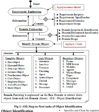
This is the Sequential steps to acquire the Object from the Business Model and SRSs. Firstly, the Requirements are engineered by the given steps, from the business model, using this the base domain is identified by the given steps, then the foresting rules is applied for sub-domains (using Forest rule) are designed as source to sink area of each sub-domain. Then Related Object is identified from each sub-domain by the applying related Object Identification tools. After that interactions and interfaces applied for each sub-domain for integration of the system.
Fig 1: (OI) Step-to-Next tasks of Object Identification
4.2 Step-to-Next Object Identification
workout
The System Requirements Specification and Software Requirements Specification with business logic are the founder tasks of the requirement engineering. And requirement engineering is the identification of the system needs. Using these tasks, the domain is designed, for cover the area for system achievement [21]. Using requirement engineering, the following decomposition tasks are to be carried out for acquires system outlet.
1. Requirement Inception
Origin the sources of information acquire getting business logic and SRSs
Initialize the scope of requirement
Find out the sources of Information acquisition
2. Requirement Specification
Identify the source and sink of requirement
Decompose the requirement for Information acquisition
Identify the source and sink of each disintegration
Specifies and Clean the requirements
Documents of each tasks of the requirements
Design the Base and Derived requirements
4. Requirement Design
Encompasses the decomposed tasks
Interface and interaction between each decomposed tasks
Design the structures of the each tasks
Design the requirements framework
After the requirement engineering, the source and sink of Domain to be engineered, using the Domain Engineering, also designs sub-domains, the following tasks applied for domain design.
1. Domain Inception & Identification
Identifies the source and sink of domain
Design the domain scopes
2. Domain Elicitation & Specification
4. Domain Design
Encompasses the decomposed domain using Domain Interfaces
Integrate each decomposed domain using Interface and interaction between them
Design the domain framework
After the domain engineering, the System objects like tangible, link and boundary objects are identified, also identified the common objects with common attributes and common operations of the each object, also identification of the related attributes and operations of the each identified object.
4.3 Object Identification tools
4.3.1
Use Cases:
Use Cases most important tool to identify the primary elements and processes that form the system. Here primary elements are Actors and processes are called use-cases. Both tasks indicate which actor interacts with each use-case. Basically link and tangible object are identified using use cases as well as business logics are incepted [5][14]. The Actors are must be tangible or boundary objects, and use-cases incept operations and transaction/automation by the business logic, and come out the link objects from the operations as well as unveil the lexicons.
Fig 2: Link & Tangible Object Identify by Use Cases
4.3.2
Scenario
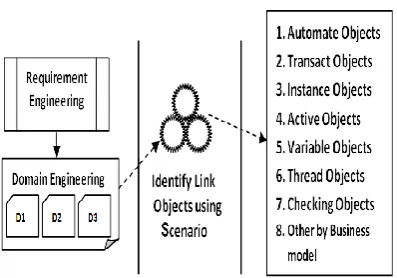
Scenario is also most important tool using scenario it is specified sequence of actions/events and interaction between actors and system. Scenario is also called use case instance .An event occurs whenever information is exchanged between an object in the system and out site agents, such as users, a sensor, or another task. The information values exchanged are parameters of the events. Scenario encompasses the individual actor tasks/operations to be performed in the module, sub module or system [12]. Here primary work of the scenario is design and encompass the work tasks of each actor to be performed for events using business logic using this below objects are identified from the scenario. Also using the scenario design, it is identified the interface and interactions among the objects.
Fig 3: Instance/Activate Object Identify by Scenario
4.3.3
Domain Specification:
A Domain is boundary form source to sink, incepted and specified by the requirement engineering. It is the conceptual model depicts the objects that are easily identified. Using Domain engineering, the domain is divided into forest (sub-domain) for the extract the objects from each sub-domain and we can identify the all three type of objects as tangible, link and boundary objects. Basically domain specification is depends on requirements engineering and requirements engineering is extracted from the system and software requirement specification.
Base Domain:
Fig 4: Relational Interfaces in Domain Foresting
4.3.4
EFD, IFD, DFD and ERD:
Fig 5: Event Flow Diagram
Above diagram denotes the Actor(s) interactions between Actors. The Interaction constructs the Link Objects form the Dialogs between Objects. The <<?>> Denotes the types of interactions between object.
5.
EXPERIMENTAL RESULT
5.1 Generic algorithm of Object
Identifications
The Sequential steps are designed by the following algorithm to extract the generic objects from Domain, here domain is engineered into the foresting in component design, and System objects are extracted from each Domain foresting (Sub-Domain) by the above Object Identification Tools, and further engineered for the Base Objects and genericity for commonness, after that Component and Deployment design applied for Object Interfaces. The following algorithm denotes the sequential steps to identify the common objects
Step 1. Mining the requirements using the SRS, SRS and Business Model/Logic
Step 2. Design Requirement Engineering
Step 3. Identify the Domain, by Requirement Engineering
Step 4. Foresting (Domain dissection) according to business model
Step 5. Apply the Object Identification tools to each sub-domain
Step 6. Identifies related Objects from each sub- domains
Step 7. IF each sub-domain <> SRS and SRS and Business logic THEN
GOTO Step 6
Else GOTO Step 8
Step 8. Encompass sub-domains
Step 9. Design Interface and interaction between each sub-domain
Step 10. IF Domain <> SRS and SRS and Business logic THEN
Tangible and Link Objects
Step 13. Design the sub-domain relation
Step 14. Finish
5.2 Sequential Step-to-Next tasks of I.O
using PERT chart
Step-to-Next
Sequence Tasks
S
te
p
1
S
te
p
2
S
te
p
3
S
te
p
4
S
te
p
5
S
te
p
6
S
te
p
7
S
te
p
8
S
te
p
9
S
te
p
1
0
Get hold of business model
Requirement Engineering Domain Engineering (Base Domain) Domain Foresting (sub-domain) Appling O.I tools to each sub-domain Identify Related Objects from each sub-domain
Relational interface of Domain foresting
Bifurcation of Objects
Identify Base and generic Objects Design the sub-domain relation
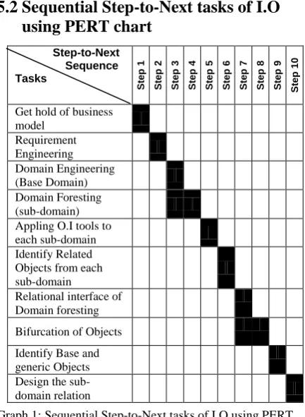
Graph 1: Sequential Step-to-Next tasks of I.O using PERT
Above graph 1 PERT Chart are designed for variation of the Step-to-Next tasks to be forwarded for an Object Identification. The chart also denotes the independent and parallel tasks are to be carried out from business model to domain relation design. Here independent task denotes the entirely committed tasks, to forward to go next sequential step. The darken area denotes the work being carried out of the each task either in independent or parallel.
5.3 Assertion of the each task
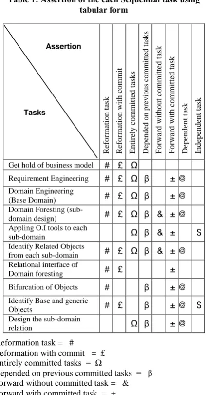
Table 1: Assertion of the each Sequential task using tabular form Assertion Tasks R ef o rm at io n t as k R ef o rm at io n w it h c o m m it E n ti re ly c o m m it te d t as k s D ep en d ed o n p re v io u s co mm it te d t as k s F o rw ar d w it h o u t co m m it te d t as k F o rw ar d w it h c o m m it te d t as k D ep en d en t ta sk In d ep en d en t ta sk
Get hold of business model # £ Ω
Requirement Engineering # £ Ω β ± @
Domain Engineering
(Base Domain) # £ Ω β ± @
Domain Foresting
(sub-domain design) # £ Ω β & ± @
Appling O.I tools to each
sub-domain Ω β & ± $
Identify Related Objects
from each sub-domain # £ Ω β & ± @
Relational interface of
Domain foresting # £ ±
Bifurcation of Objects # β ± @
Identify Base and generic
Objects # £ β ± @ $
Design the sub-domain
relation Ω β ± @
Reformation task = # Reformation with commit = £ Entirely committed tasks = Ω
Depended on previous committed tasks = β Forward without committed task = & Forward with committed task = ± Dependent task = @
Independent task = $
6.
CONCLUSION
Object Identification is vital and challenging tasks to developing large and complex software application in cross languages for independent platform, Object is the foundation for the application development, exhausting from the problem of require architectural framework for object identification, and it is essential for software developments in cross programming languages; we are trying to give the experimental step-to-next object identification tasks and Object Identification tools as well as generic algorithm for acquiring common/Generic Objects from the domain which is extracted from the Requirements engineering tasks. Here Requirements engineering is a vital and fundamental aspect of software, a requirement is an expression of desired behavior. A requirement deals with objects and it is instinctive from the business model. The step-to-next tasks are methodological sequence of the object extraction.
7.
ACKNOWLEDGEMENT
We would like to thanks Respected Dr. Samrat. O Khanna, Head of the IT Departments of ISTAR institute of the V.V Nagar-Anand-Gujarat-India, to inspire and encouraged to
perform over best. And we also Thanks to all Software firms who gave me the best support to abstract my goal.
8.
REFERENCES
[1] Bernd Bruegge, Allen H. Dutoit. “Object Oriented Software Engineering, Using UML, Patterns, and Java”, Second Edition, Pearson Education, 2010. [2] Code P. Yourdon. E. “Object Oriented Analysis”, 2nd
Addi., Yorden press, Englewood Cliffs,1991.
[3] Craig Larman. “Applying UML and Patterns”, 3rd Addition, Pearson Education Inc. 2005.
[4] Desmond Francis D’ Souza and Alan Cameron Wills. “Objects, Components, and Framework with UML”, 2nd Addition, Addition-Wesley Object Technology Series 1999.
[5] Geri Schneider, Jason P. Winters. “Applying Use Cases”, 2nd Addition, Addition-Wesley Object Technology Series 1998.
[6] Grady Booch. “Object Solutions”, 2nd Addition, Addition-Wesley Object Technology Series 1996.
[7] Heninger K.L, “Specifying software requirements for complex systems”, New techniques and their applications. IEEE Transactions on Software Engineering 6 (1), p. 2-13, 1980.
[8] Ivan. Jacobson, G. Booch, and J. Rumbaugh, “The Unified Software Development Process”, Addison- Wesley, 3rd Edition, 1999.
[9] Ivan. Jacobson, G. Booch, and J. Rumbaugh, “UML Modeling Language Reference Manual”, Addison- Wesley An Important Addition, 1999.
[10]Ian Somerville, “Software Engineering”, 6th Edition, Pearson Education, 2005.
[11]James J, Odell, “Advanced Object Oriented Analysis and Design by UML”, Pearson Education, Cambridge University Press, 1998.
[12]James Rumbhaugh, Michael Blaha, William Premerlani, Frederick Eddy, William Lorensen, “Object Oriented Modeling and Design”, Prentice- Hall India Edition, 3rd Edition, 2001.
[13]Jaya Vijayan, G. Raju., “Requirements Elicitation Using Paper Prototype”, Advanced in Software Engineering, International Conference 2010, Springer p. 30-37, 2010.
[14]Jim Arlow, Ila Neustadt. “UML and the Unified Process”, 2nd Addition, Addition-Wesley, Object Technology Series, 2002.
[15]Rajib Mall, “Fundamental of Software Engineering”, 3rd Edition, Prentice- Hall India eddi. 2008.
[16]Civello F “Roles for composite Objects in Object Oriented Analysis and Design, OOPSLA, ACM SIGSOFT Vol. 28 No. 10 ,pp 376-393.
[17]Hoyalsvik G M and Sindre G “ On the purposr of Object Oriented Analysis”, OOPSLA’93, ACM SIGSOFT, Vol. 28 No. 10, pp 240-253.
[19]Kim W Bertino, J Chou, H T Garza and Woelk D ”Composite Object Support in Object Oriented Database System”, OOPSLA’87 Proceeding (1987), pp 118-125. [20]Liveri J, “Relationships, Aggregations and Complex
Objects”, Information Modeling and Knowledge Base III Amsterdam, IOS Press (1992).
[21]Sonar sanjay Bhagwan “The Common Interface Oriented Architectural Framework to Improve Compatibility of
the Pure Object Oriented Cross Languages Interoperability”, The International Journal of Computer Science Trends and Technology (IJCST), Volume 2 Issue 3, 2014.
[22]Sonar sanjay Bhagwan “Interoperability in the JVM and