for sand macrofaunas
PETER R. O. BARNETT and BERNARD L. S. HARDY
Marine Station, Millport, Scotland
K U R Z F A S S U N G : Ein vom Taucher bet~itigtes Ger~it zur quantitativen Entnahme der Makrofauna auf Sandb6den. Zur Entnahme quantitativer Proben der Makrofauna aus festem Sandboden gibt es nur zwei Ger~.te, die beide sehr schwer sind und einer kr~iftigen Winde auf einem grof~en Schiff bed~irfen: (a) der Knudsengreifer (0,1 m 2 Fl~iche, 30 cm Einstichtiefe, 150 kg) und (b) der Kastengreifer yon Reineck (20 X 30 cm Fl~iche, 40 cm Einstichtiefe, 750 kg). Fiir Untersuchungen fiber die Verteilung benthischer Makrofauna innerhalb kleiner Gebiete war jedoch ein Ger~.t zur Entnahme yon Bodenproben erwfinscht, das von einem Taucher ge- zielt eingesetzt werden kann. Eine Sammeltiefe yon mehr als 30 beziehungsweise 40 cm war erforderlich, um den Fang der tiefer grabenden Arten, beispielsweise der Muschel
Lutraria,
zu gew~ihrleisten. Das neue Ger~it wurde zweiteilig entworfen. Der eine Tell besteht aus einem offenen Stahlzylinder, der eine L~inge yon 60 cm und eine Grundfl~iche yon 0,1 m 2 aufweist. Er wird zun~ichst mit Handkra~ senkrecht in den Boden hineingeprei~t, damit er vom Sand gut abgedichtet wird. Das obere Ende wird anschlief~end mit einem De&el verschlossen, und das Wasser, das sich im Zylinder oberhalb des Sedimentes befindet, wird durch eine Pumpe abgesogen. Der hydrostatische Druck auf den Deckel pret~t den Zylinder in den Sand. Wenn der Zylinder v611ig in das Sediment versenkt ist, wird der De&el entfernt und der vom Zylinder umfa~te Sand dutch den zweiten Teil des Ger~ites ausgesaugt. Dieser besteht aus einer langen Kunststoffr/Shre yon etwa 8 bis 10 cm Durchmesser. Sie wird in senkrechter Stellung v611ig unter Wasser gehalten. Wird Lui°c unter Druck in das untere Ende eingeleitet, so funk- tioniert die R/Shre als eine Lu~hebepumpe. Ein speziell gebautes Sieb ist am oberen Ende des Steigrohres befestigt. Der Taucher ffihrt das untere Ende dieser Saugpumpe in den Zylinder und saugt dessen Inhalt in das Sieb hinein. Die Druckluf~ fiir die Bet~itigung des Instrumentes wird yon einem Kompressor oder aus Drucklut°cflaschen (4-5 m 3) geliefert. Das beschriebene Get,it ist leicht und kann deshalb mfihelos yore Taucher bedient werden. Es kann yon Klein- booten aus eingesetzt werden und ben6tigt keine Winde.I N T R O D U C T I O N
Bottom sampler for sand macrofaunas 391
techniques are the only satisfactory w a y of carrying out observational and quanti- tative studies on hard bottoms. RIEDL (1960), for example, has shown that dredges are useless for assessing quantitatively the fauna of submerged rocks. On the other hand, for level bottom communities, there are a number of qualitative dredges and quantitative grabs and corers which the non-diving biologist can use from a boat. Another reason why the rocky seabed has received more attention from divers is probably because, having a visible epifauna, it presents more attractive prospects than level bottoms of sand and mud where the burrowing fauna is largely hidden.
It might be argued, therefore, that there is little point in the diver devoting much attention to level sand bottoms. LONGHtmST (1964) has pointed out that it is uncertain whether a diver can perform a quadrat survey of the burrowing infaunal animals o~ deposit substrata more efficiently than can a grab operated from the surface. In many ecological surveys this is probably true but there are certain types of survey on sand bottoms where the presence of a diver becomes very necessary.
Whilst carrying out benthic surveys on a medium grade sand at a depth of 10 m at Millport, it became clear that very considerable variations occurred in the distri- bution of infaunal species within small areas of the bottom. In order to carry out studies on the distribution patterns of these species, it is necessary to lay out sampling grids on the bottom and to take quantitative samples of the burrowing infauna at selected points. Such work can, of course, only be undertaken by divers.
The only samplers, operated from a boat, capable of taking deep quantitative samples of macrofauna in hard sands are the KNUDSEN 0.1 m 2 bottom corer (KNuDS~N 1927) and the REINZCK box sampler (REINECK 1961). These instruments are too heavy for divers to handle and require a powerful winch.
BREvet (1964) has described a portable diver-operated hydraulic sampler which produces suction by the aspirator principle using a jet of water from a portable pump. The dredge is used to suck sand and animals from within a steel frame of known area which is placed on the bottom. This sampling frame is 15 cm deep and is driven into the sediment by hand. BR~TT'S sediments were such that when the ground was too hard for the frame to be driven in to its full depth, there was no problem of sampling deeper than the frame since the walls of the dredged hole remained firm, and uniform samples were always obtained.
Some Millport sediments proved to be too hard for the BR~TT type of frame to be driven in by hand for more than a few centimetres but were not cohesive enough for the sides of the hole to remain firm when sampling below the level of the frame. Furthermore, a sediment depth greater than 30 cm was required since it was observed that even the K~uDs~N bottom sampler, digging to a maximum depth of 30 cm, some- times fails to capture all the common deeper burrowing species (e. g. Ensis arcuatus
and Lutraria lutraria). Furthermore, it was found that the BR~TT type of suction
device did not work satisfactorily on some hard packed sands.
D E S C R I P T I O N A N D O P E R A T I O N
The sampler is designed basically in two parts. The first part is a cylinder which is pushed into the sand to enclose a known surface area to a known depth. The second part is a suction pump which is used to excavate and sieve the sand and animals from within the cylinder.
S a m p l e c y l i n d e r
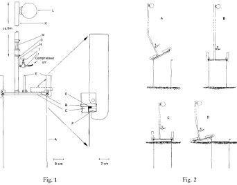
Details of the sample cylinder are shown in Figure 1. The cylinder A is made of 1.5 m m (1/1~ inch) thick sheet steel. It is 60 cm (23.6 inches) tall with an internal diameter of 35.7 cm (14.05 inches) and has a cross-sectional area of 0.1 ms.
B is a circular steel lid, 4.8 m m (3/10 inch) thick, which fits over the top of the cylinder. A 1.3 cm (1/2 inch) thick marine plywood disc C, bolted to the underside
I
c o 6 m/
/
D
8 c r n 2 c r n
A
~1 c
Fig. 1 Fig. 2
Fig. 1: Cross section showing details of the sampling cylinder. Letters referred to in the text Fig. 2: Diagrammatic cross sections of the sampling cylinder showing the stages of
sand penetration
Bottom sampler for sand macrofaunas 393
welded to the centre of the lid (not illustrated) is used for lowering the sampler to the bottom.
The lid can be held in place over the top of the cylinder by means of the four clamps E (Fig. 1), which grip a narrow rim F. Each clamp is designed so that as the hooked end engages the rim F, the rubber gasket D is gradually compressed by 1.6 m m (I/16 inch) until the clamp is fully in place. The rubber gasket thus provides a water- tight seal between the lid and cylinder. The clamps are easily manipulated by a diver and when in position are held in place by the gasket expanding against the lid. When not in use the clamps lie, out of the way, horizontally on the upper surface of the lid. A 2.5 cm bore (1 inch British Standard Pipe) steel pipe G, about 30 cm (12 inches long), is screwed into the upper surface of the lid on one of the inter-radii between the four clamps. This pipe has a small 1 cm (a/8 inch) diameter tube H brazed halfway along its length, to which a small 3 m m (1/s inch) globe valve I is screwed. J is a tube similar to H, to which a high pressure rubber or plastic hose carrying compressed air can be attached. K is a 2.5 cm (1 inch) bore plastic hose about 6 m (20 &) long. It is attached to the pipe G by a worm-drive hose clip and is supported vertically under- water by a small plastic trawl float L. The hose K and pipe G are made to work as an airli& pump by a flow of compressed air controlled by the valve I. The flow of air up the hose K can be controlled by watching the rising air bubbles through a piece of Perspex tube M inserted into the hose near its lower end.
In practice, the 0.1 m s cylinder is placed on the seabed and pushed a few centi- metres into the sand by hand (Fig. 2 A). The lid is then secured in position by means of the four clamps (Fig. 2 B). The air supply to the airlif~ pump is turned on slowly and water is pumped out of the cylinder. The head of water above the lid then forces the cylinder into the sand (Fig. 2 C). Tests with a manometer fitted to the cylinder lid have shown that the force exerted on the lid during penetration of a medium grade sand is 70 g/1 cm -° (1 pound/sq, inch), a total force on the lid of 70 kg (155 pounds). The diver should transmit a semi-rotary motion to the cylinder whilst it is penetrating the sand for the first few centimetres. It is very important that, in this manner, a good seal is created between the lower, open end of the cylinder and the sand; otherwise the sand seal collapses and water is merely pumped straight through the cylinder and up the airli~ pump. Penetration of the cylinder to a depth of 60 cm usually takes about five minutes. The clamps are then released, the lid is removed (Fig. 2 D) and the sand enclosed by the cylinder is now ready for removal by the second part of the sampler.
S u c t i o n p i p e
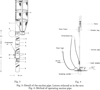
For ease of handling out of water the suction pipe is made of 3 m (10 it) lengths connected together with plastic union joints (P). The number of lengths used depends on the depth of water. The lowest length N is plain ended whereas subsequent lengths (e. g. 0) each have a union joint cemented to the lower end.
The suction pipe is weighted at one end by a series of five lead weights (Q) and has five trawl floats (R) at the other end so that when the pipe is submerged it remains vertical in the water. The lead weights are each 7.0 cm (2.75 inches) long by 11.0 cm (4.3 inches) diameter cylinders, having a bore of 8.8 cm (3.5 inches). They are designed
3 m
' ~
0
Compressed p
air \
,'::, N
3m V - - - - S T ~ U
10 cm
Trawl floats
~ '
- - S i e v e I SampLe bagCompressed
aii~ ~
Trawl float
I
Air-Lift
hose
)
Sampling cylinder f - - - >
Suction pipe
-Lead weights
- )
Fig. 3 Fig. 4
Fig. 3: Detail of the suction pipe. Letters referred to in the text Fig. 4: Method of operating suction pipe
to slide on to the pipe N and rest on a 1.25 cm (1/2 inch) wide plastic ledge S cemented to the outside of N. It is convenient to arrange for the weight of each to be about the same as the buoyancy of each of the floats R (3.175 Kg or 7 pounds). In this way, the use of the same number of floats as weights gives neutral buoyancy. The small weight of the plastic pipe then makes the suction pipe sink to the bottom but allows it to be moved easily by the diver.
Bottom sampler for sand macrofaunas 395
cemented to the inside of each end of T. A series of 1.5 mm (1/18 inch) diameter holes is drilled in several rows through the wall of pipe N, 60 cm (23.6 inches) from its lower end. The internal diameter of each ring (U) is carefully machined to make an air-tight fit with the suction pipe N. The air chamber can thus be moved along the suction pipe, by tapping gently with a hammer, to expose the small air holes for cleaning in case these become blo&ed with sand.
V is a 1.7 cm (0.7 inch) diameter plastic pipe cemented into the wall of the air chamber T and is connected to a small 3 mm (*/8 inch) globe valve W by a short length of plastic or rubber hose. Compressed air, controlled by the valve W, passes into the air chamber T and through the series of small holes into the lumen of the suction pipe where it produces an air-water mixture of lower density than that of the sur- rounding water. The less dense mixture rises in the pipe, and water is drawn in at the lower end with considerable suction. Air is injected into the suction pipe through a series of small holes rather than a single large hole because the smaller air bubbles produce a more efficient airli~ pump (GIBSON 1925). This is an important factor when the sampler is being operated from compressed air storage cylinders.
At the upper end of the suction pipe is a specially designed sieve X. It is con- structed with a framework of "Durapipe" plastic strips cemented together. With the exception of the two openings Y and Z, the sieve is completely enclosed by a 1 mm mesh net of Monel metal which is glued to the plastic framework with plastic cement. The sieve is of cylindrical shape and tapers at its lower end to a 15 cm (6 inch) length of 10.5 cm (4 inch) diameter plastic pipe Z to which a polythene bag is tied for collection of the sample. The suction pipe 0 fits into a 10.5 cm diameter pipe (internal bore 8.8 cm or 3.5 inches) Y embedded in the side of the sieve.
In practice, the air supply valve is turned on slowly until there is a rapid flow of water up the suction pipe. The nozzle of the pipe is then directed into the sand enclosed by the sample cylinder (Fig. 4), and the sand, and animals it contains, is sucked up into the sieve at the top. Here, most of the finer sand passes through the sieve due to the flow of water. Material too large to pass through the sieve hits the mesh and falls down the funnel and into the plastic bag.
When the sampling is completed clear seawater is allowed to be drawn into the suction pipe for a minute to clear it of all material; some heavier objects take a little longer to reach the sieve than lighter material. When the air supply is turned off the diver makes sure that nothing falls ba& down the tube. He then closes the ne& of the plastic sample bag with a cord and releases the bag from the sieve.
Personal observation shows that all the material retained within the sieve falls down into the sample bag with the exception of one or two larger brittle-stars such as
Ophiocomina nigra
which cling to the inside walls of the sieve. However, it is an easymatter to remove these by fanning water by hand through the sides of the sieve. When used on sand deposits with a median particle diameter ranging from 200 to 500 ~¢, the total time required to sink in the cylinder and take a sample of surface area 0.1 m 2 to a depth of 60 cm is about 15 minutes.
sediment. The cylinder rises rapidly through the water for a few metres before cap- sizing, losing its contained air, and sinking to the bottom again. Divers should keep well clear during this operation and should ensure that the attendant boat is not directly overhead in case the cylinder should rise to the surface.
The air supply hoses are 3.5 mm bore clear plastic flexible pipes, the walls of which are reinforced by a nylon mesh. Such hoses will withstand a pressure of 14 atmospheres. As long as there is an air supply with a pressure up to 7 atmospheres, this small bore flexible tubing delivers sufficient air, and since it coils very easily, it is more convenient to use than the thicker, heavier, rubber hosing more frequently used for these pressures. The compressed air supply for the sampler can be either a com- pressor or an air storage cylinder. At Millport storage cylinders are used which hold 4 to 5 m 3 of free air. Each is fitted with a pressure reducing valve to provide an air supply at 7 atmospheres. Such a cylinder has been used satisfactorily from a small boat. As an example of the compressed air consumption of the sampler, a sample of medium grade sand taken at a depth of 10 m with a 6 m long suction pipe normally requires about 0.5 m8 of air. A storage cylinder will thus provide sufficient air for about eight samples.
With regard to the efficient use of the compressed air, especially with storage cylinders, if a suction pipe of unit length, using a unit volume of air, is used at in- creasing depths of water, the amount of compressed air entering the suction pipe will decrease with increasing depth. However, if the pipe length is increased with depth, a greater head of water will be provided and greater suction will be created at the nozzle. For the most efficient use of compressed air, it is important therefore that the upper end of the suction pipe should be close to the surface.
As an example of the rate of flow of water up the suction pipe, a 6 m long suction pipe, working at an air pressure of 7 atmospheres with the upper end at the surface, will deliver 320 1 of water (70 gallons) per minute.
At Millport the suction pipe is normally used at a depth of 8 to 10 m, for which two 3 m lengths of pipe are coupled together. A single piece 3 m long has been found to work satisfactorily in 3 to 4 m of water, whilst COUSTEAU (quoted by FLEMMING 1962) has used suction pipes at depths of 43 m.
D I S C U S S I O N
It might be suggested that it would be more convenient to connect the upper end of the suction pipe to a sieve mounted in the boat. In practice it was found that to do this, lengths of flexible pipe had to be used to allow for independent movement by the diver at the bottom and the boat at the top of the pipe. Such flexible pipes presented considerable difficulties due to the fact that larger molluscs like Ensis and
Lutraria frequently stuck at the inevitable bends in the flexible pipe. It was found that it is better to use a rigid vertical tube with a smooth internal wall and to have the sieving apparatus entirely submerged and serviced by a diver.
Bottom sampler for sand macrofaunas 397
force to be overcome by the sample cylinder is the resistance to penetration which is, presumably, proportional to the circumference of the cylinder. The force used to overcome this resistance is the force exerted by the head of water overlying the cylinder and is proportional to the area of the lid. Therefore, since the force exerted on a cylinder varies as the square of the radius whilst the resistance varies directly with the radius, cylinders of larger area should be more effective in digging.
Whilst the application may be new, the use of the airlift: principle in both parts of this sampler is not original. MACKrRETU (1958) used an airlifL pump to drive a large cylinder, closed at the top, into the muds of lakes where it was used as an anchor chamber for a long coring device. Airli~ suction pipes have also been used by underwater archaeologists to excavate sand and silt from ancient wrecks (e. g. C o u - STEalS & Roo~I, quoted by FLEMMINO 1962). Airlii°cs have also been used to collect material on the Vema Seamount (SIMvSON & HEYDORN 1965). Civil engineers also use them to clear away stones and debris from the seabed.
S U M M A R Y
1. A new bottom sampler for macrofauna is described which is easily operated by a diver.
2. The airlitt pump principle is employed firstly to sink a sampling cylinder into the seabed and secondly to operate a suction pipe which is used to excavate sand and animals from within the cylinder.
3. The sampler covers an area of 0.1 m'-' and penetrates to a depth of 60 cm. It is particularly suitable for quantitative studies of deeper burrowing fauna (e. g. Ensis
spp. and Lutraria spp.).
4. The sampler is designed for use in sandy sediments and for studies on the dis- tribution of faunas within small areas where line transects or grids of samples are required.
A C K N O W L E D G E M E N T S
We wish to thank Mr. R. McBAY of the Marine Station, Millport, for building most of the sampler and Mr. J. S. CRAm for many discussions.
L I T E R A T U R E C I T E D
BXETT, C. E., 1964. A portable hydraulic diver operated dredge-sieve for sampling subtidal macrofauna. J. mar. Res., 22, 2, 205-209.
FLEMMI~qG, N. C., 1962. Sunken cities and forgotten wrecks. In: Oceans. Ed. by G. R. Deacon. Hamlyn, London, 123-171.
GIBsoN, A. H., 1925. Hydraulics and its applications. Van Nostrand, New York, 801 pp. KNUDSEN, M. A., 1927. A bottom sampler for hard bottom. Meddr Kornmn Havunders. (Ser.
Fisk.) 8 (3), 3-4.
MACKERETH, F. J. H., 1958. A portable core sampler for lake deposits. Limnol. Oceanogr. 3, 181-191.
REINECK, H. E., 1961. Die Herstellung yon Meeresboden-Pr~iparaten im Senckenberg-Institut Wilhelmshaven. Museurnskunde 30 (2), 87-89.
RIEDL, R., 1960. An attempt to test the efficiency of ecological field methods and the validity of their results. In: Perspectives in marine biology. Ed. by A. A. Buzzati-Traverso. Univ. of Calif. pr., Berkeley, 57-65.
SIMVSON, E. W. S. & HEYDORN, A. E. F., 1965. Vema seamount. Nature, Lond. 207, 249-251.
Discussion following the paper by BAt~NETT & HARDY
FORSTER: Are there any problems with muddy deposits making visibility difficult for the diver?
BARNETT: The sampler has not been used on muds. When used on a sand with some silt, we have no trouble. The 6 m long suction pipe carries the turbidity weI1 away from the diver. MASSif: Je suis tr~s interess6 par votre appareih Nous utilisons ~t Marseille l'appareil de BRETT qui est plus simple b. manipuler que votre appareil. Nous avons r&olu le probl~me du pr6- l~vement quantitatif en utilisant non pas le cadre m&allique de 15 cm, mais un cylindre de 45 cm de haut que nous enfonFons ~t la main dans le sddiment qui est en g6n6ral un sable fin propre. Pourquoi n'avez vous pas utilis6 l'appareil de BI~ETT?
BARNETT: At Millport we built a BRETT type of sampler but could not get it to work pro- perly. I understand that M. MAssE has been successful in this at Marseille, and it will be interesting to know how he has modified BRETT'S sampler. When using the BRETT type of frame we could not, in our sediments, push it in more than about 10 cm. We therefore employed another source of power, and we found t h a t the airli~ could be used successfully. Since we required compressed air for the sampling cylinder, we decided to use it for the suction pump.
MAssE: Je ne savais pas que les fonds sur lesquels vous travaillez etaient si durs. Je vous signale que J. P. REYS, M. TI~uE et R. TRuE-SCHLENZ ont pr6sent6 au Congr& de Moscou un appareil de BRETT autonome off le cylindre s'enfonce tout seul; peut-&re devriez-vous l'essayer car son utilisation est plus simple que celie de votre appareil si toutefois la compacit6 de vos fonds le permet.
BARNETT: Yes, I think the water jet principle as a method of sinking a cylinder into the sediment will be particularly useful when used at depths greater than those used by divers. With increasing depth, compressed air becomes less efficient, and there is a limit to the length of the suction pipe which can be used.
HARTNOLC: When the sampling cylinder has been emptied, is there not a risk of sand from the outside entering at the lower end?