EAI Endorsed
on
Industrial Networks And Intelligent Systems
Cloud Based Mobile Network Sharing: A New Model
Malla
Reddy
Sama
∗,1,
Yvon
Gourhant
1and
Lucian
Suciu
11 Orange Labs, France
Abstract
Thetraditionnetworksharingmodelsonexistingmobilearchitectureisachallengingforthemobileoperator tocopethefuturecompetitivemarketwhileincreasingaveragerevenueperuser.Infact,tosustainthefuture datatsunami,theoperatorsarealreadyinvestingintheirnetwork.However,theyarenotyetcapturingtheir investments.Theaveragerevenueperuserhasdeclined.Moreover,thestaticandrapidcommoditizationof networkequipmentsandserviceprovisioningarepushingthemobileoperators’toadoptdifferentstrategies suchasnetworkingsharingintheaccessandcorenetworkfortoreduceOPEXandCAPEX.Inthispaper,we proposednewmodelsformobileoperatorstosharetheirnetworkthroughcloudplatform(e.g.pay-as-you-go) inordertoopennewbusinessstrategiesandtoreduceCAPEXandOPEX.Ontheotherhand,thisproposal alsocopsthefuturedatatsunamiandintroducesmore flexibility,e lasticitya ndo n-demandfeaturest othe LTE/EPCarchitecture.
Keywords: LTE/EPC, Cloudification, Infrastructure sharing, MVNO and Emerging Markets.
1. Introduction
New market liberalization developments around the
world and growing mobile data traffic drive; dramatic
and fundamental technological changes the telecom sector landscape. After dramatic changes in mobile phones and new innovations in the mobile network, LTE/EPC (Long Term Evolution/Evolved Packet Core) is a perfect example for this liberation changes in telecom sector. These enormous successes of the telecom industries in worldwide, the current architecture imposes challenges for mobile operators in order to introduce new business model for increasing the revenue and to cope the future data tsunami
[1]. For example, the mobile operators has been
struggling to cope with the increasing data demands of new devices like tablets, smartphones and their rich applications like multimedia services. However, they are not been able to take full advantages of the higher transmission technology like LTE. Among the key reason for this shortfall is the custom equipment, static network equipment behavior and computationally heavy protocols are ultimately leading to high CAPEX and increasing network operational cost.
In addition, the current LTE/EPC architecture was not designed with enough flexibility in mind. Its components like eNB, MME, SGW and PGW are based on custom hardware and need to be
statically provisioned and configured [2]. Indeed, these
∗
Corresponding author. Email:[email protected]
components are too expensive, vendor lock-in, too
complicated to manage and change their behavior.
Consequently,thenetworkarchitecturedoesnotcome
with enough flexiblea nde xtensiblef eatures.The
network is typically dimensioned based on the load
foreseen at the peak hours. For example, to increase
the network capacity and configuren ewf unctions,it
requires the deployment of new entities in specific
network sites and to integrate them smoothly in the
existing network. Hence, the operation of such a
static and device-centric network management is a
costly, cumbersome and time-consuming process [3].
Unfortunately, this state-of-affairs has remained true
for well over two decades. In fact, the operators
are prohibited to change any software function or
implement any new functions in the network entity.
Often,theoperatorhavetowaitforavendortoput it
inplanintheirproprietaryproducts.Significantly,this
willputgreaterstrainonnetworkoperatorsbecauseit
mayincreasetheOPEX.
On the other hand, the mobile operators are facing a strong competition environment. A recent study shows that the operators’ revenues are decreasing exponentially and faces “end of profit" sometime before
mid-2015 [4]. In fact, the cost to build, upgrade and
operate the network is becoming too expensive while the revenue is not growing at the same rate. In addition
to this, mobile data traffic has been growing at an
unprecedented rate over the last few years [5], while the
ARPU (Average Revenue Per User) is decreasing slowly
([6], [7]). This will impact the ability to build out new
Research Article
Received on 02 February 2014, accepted on 18November 2014, published on 08 May 2015
Copyright © 2015 Malla Reddy Sama et al., licensed to ICST. This is an open access article distributed under the terms of the Creative Commons Attribution licence (http://creativecommons.org/licenses/by/3.0/), which permits unlimited use, distribution and reproduction in any medium so long as the original work is properly cited.
networks and offer new services. In this predication, the mobile operators must rethink about their solution in order to reduce cost and to maintain profitability and growth as well as to provide better services to the end users.
On these grounds, network operators should inves-tigate new solutions to manage the dynamic nature of
future traffic in a cost-efficient manner. There have been
studies ([8], [9], [10] and [11]) and standardization
bod-ies such as ONF Wireless & Mobile group [13] and ETSI
NFV [12] that address the challenge caused by mobile
data traffic increase in LTE/EPC architectures and
high-lighted the immediate need for the reduction of net-work costs both OPEX and CAPEX. For instance, in
[11], the authors explored OpenFlow as an architecture
for eNode B virtualization and infrastructure sharing between operators. Thus, the operators recognize the opportunity to tap into advanced technologies such as
server virtualization, efficient traffic management, and
automation tools in order to reduce overall operating cost and provide Quality of Experience (QoE) adapted to user needs.
A trend consists of sharing infrastructure between operators (passive infrastructure sharing or even RAN
sharing) in order to reduce costs ([14], [15]). But
unfor-tunately, it reduces also revenues and decrease network competition between operators. Outsourcing passive infrastructure to Tower Co, network management to equipment vendors, or even IT management to IT
vendors is another current trend [16]. But it reduces
the knowledge on troubleshooting and the control on the network evolutions. Infrastructure sharing and out-sourcing may be combined through a joint venture. This is a possible solution for emerging markets but we suggest applying them only to the access network because the core network has a lower cost than access but much more intelligence needed for feeding compe-tition. Therefore, we suggest looking at other ways to mutualize the core network for reducing its cost but still keeping the control by operators and the competition between them.
2. LTE/EPC Architecture
The LTE/EPC architecture aims at providing seamless internet connectivity between UE and EPC. The EPC has a flat, all-IP architecture with separation of control plane and data plane. The architecture is composed of the Evolved Universal Terrestrial Radio Access Network
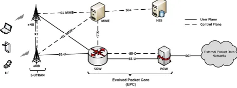
(E-UTRAN) and the EPC core as shown in Fig.1. The
E-UTRAN handles the radio communications between the UE and the EPC and has one component only, the evolved base stations, called eNodeB (eNB). The base station that is communicating with a UE is known as its serving eNB. Each eNB connects with the EPC by means of the S1 interface and it can also be connected
to nearby eNB by the X2 interface, which is mainly used for signaling and packet forwarding during handover.
SGi
S1
1
S6a S1-MME
S1-MME
MME
SGW PGW
HSS
S5-C
eNB eNB
S1-U
S5-U
External Packet Data Networks
Control Plane User Plane
Evolved Packet Core (EPC)
E-UTRAN UE
X2
Figure 1. The LTE/EPC architecture
The EPC consists in four network elements namely Serving Gateway (SGW), PDN Gateway (PGW), Mobil-ity Management EntMobil-ity (MME), and Home Subscriber
Server (HSS) [17]. The UE connects to eNB, the eNB
directs data traffic to SGW and PGW in a GTP tunnel
and for the control traffic it directs to MME. The MME
acts as the manager of the network connectivity and it plays an important role in LTE/EPC architecture. In fact, the MME is the main signaling node in the EPC. It is responsible for UE authentication and authorization, UE session setup, and intra-3GPP mobility manage-ment. The SGW and PGW are responsible for data forwarding, IP mobility and QoS control at the data plane. The PGW communicates with the outside world (i.e. PDN Network), using SGi interface. Each packet data network is identified by an access point name
(APN). The QoS level that should be affected to each
bearer is decided by the PGW. The MME is connected to SGW by means of S11 interface. The SGW is connected to PGW by means of S5 interface.
2.1. Existing sharing models and cloud based
solutions
In mature mobile markets revenue growth is limited or total industry revenue may even decline. In this situation, the only way to grow cash flow is to reduce an Operating Expenditure (OPEX) and also a future Capital Expenditure (CAPEX). Infrastructure sharing between the Mobile Network Operators (MNOs) and Mobile Virtual Network Operators (MVNOs) are the primary and well know model to reduces the both OPAEX and CAPEX. For instance, the network sharing
between AT&T and T-Mobile in USA [18], 3G RAN
sharing between T-Mobile & 3 in UK, Vodafone & 3 in Sweden, and Orange & Vodafone in Spain. This significant sharing translates into 43% saving in CAPEX
and 49% in OPEX [19]. In addition, the estimated
CAPEX savings on infrastructure sharing in the Middle
East and Africa region amount to $ 8 billion [20].
the MVNOs markets are growing faster and estimated CAGR of MVNO subscriber is 10% over the next
five years [21]. In fact, MVNOs requires the lowest
investments (sharing infrastructure with MNOs (i.e. access network)) and also requires very short time to enter into the market.
On the other hand, a new trend started to reduce OPEX and also future CAPEX such as virtualization and cloud based network (i.e. C-RAN and vEPC). The estimated virtualization and mobile cloud to
be a $400 Million Market by 2018 [23]. The main
idea of virtualization and cloud technology is to runs the appliances on high volume servers instead of running on dedicated proprietary hardware (i.e.
vendor depended physical monolithic devices) [12]. For
instance, the C-RAN project by China Mobile is to centralize all BBUs, layer 2 and layer 3 functions and estimated the reduction of both OPEX and CAPEX will be 53% and 30% including energy and maintains of the
network [24] and pooling the base band units [25].
3. Cloud based Mobile Network
Moving the mobile network into the cloud platforms, create the opportunity for the mobile operators to move
towards a completely different network paradigm,
where network entities functions such as BBU, MME, SGW and PGW are implemented by applications running on IT hardware being part of a cloud infrastructure. All these functions are bound to a specific location and dynamically scale up/down based on time-based requirements. For instance, some of functions can scale down while moving active workload to another same function in the same location or in
a different cloud center, without causing any service
interruption to the users [26]. In addition, present
static functionality of entities can be more dynamic implementation based on time of the day.
eNB
External Packet Data Networks
eNB eNB
eNB eNB
eNB eNB
Admin
eNB eNB
eNB
Cloud RAN Cloud EPC
Cloud Manager SDN Controller Cloud Manager
Voice Traffic Web Traffic FTP Traffic
Area 1
Area 2
Area 3
Backhaul
Figure 2. Cloud based mobile network
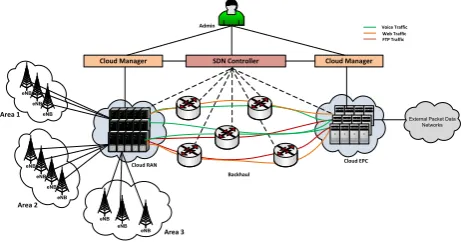
The Fig. 2 shows the proposed cloud based mobile
network. The cloud RAN connects to different eNode
Bs in pools on one side and on the other side, it
connects to cloud EPC. The data and control traffic from
UE goes to appropriate EPC cloud through backhaul. This cloud infrastructure managed by their cloud manager and backhaul which include switches and routes are managed by the software defined networking (SDN) controller. The admin views and program the network through control platform such as cloud manager and SDN controller using Graphical user interface (GUI)/Application programming interface (API) interfaces and admin can also command the network to change the network behavior or change the entity location or allocate more resource to specific site. The control platform entities such as cloud manager and SDN controller have an interface between each other. These interfaces exchange the messages, if any changes in the network behavior or any network entity scale up/down in cloud especially in the cloud EPC. For example, if any entity in cloud EPC is relocated to another location within same cloud or other cloud near to user location for better QoE. In this case, the controllers will steer dynamically the active sessions to new cloud site without any interruption.
3.1. Cloud RAN
The Cloud RAN (C-RAN) is composed of a centralized software-based Base Band Units (BBUs) and distributed low-cost remote radio heads (RRHs) plus antennas which are located at the remote site such as eNB. The RRH converts the digital baseband signals from BBU and it composed of RF devices (AMP) and signal processing units including digital to analog converter
[27]. The BBU is responsible for digital baseband
signal processing and it is the termination point for IP packet and baseband signaling as shown in Fig.
3a. For instance, the baseband signals are received
from remote cell sites are demodulated and IP packets are transmitted to the EPC. The BBU and remote cell site unit connected with each other using an optical standard interface CPRI (Common Public Radio
Interface) [28].
AMP TRX
RRH
RRH
BB
APL
BBU
CNT
eNB eNB
eNB
eNB eNB
X
2
C-RAN 1
C-RAN 2
(a) eNB (b)
Figure 3. (a). eNB architecture, (b) Each cloud platform
connected with other cloud platform by using X2 interfaces.
In the C-RAN platform, based on traffic volume
power consumed by air conditioning and number of equipment room at sites can be reduced significantly
([29], [30]). On the other hand, this centralized BBUs
can scale up/down for maximizing the resources. For instance, if an operator wants to increase the network capacity, in traditional way, the operator will increases the capacity by installing a new cell site including all RAN equipment like BBUs, RRUs, etc. In C-RAN case, the operator only need to deploy the antenna and RRU, and connect to the BBU pool in the cloud platform. The operator only need to upgrade the BBU pools hardware, when the network processing capacity increases. In addition, any upgrades in the radio interface can
be done easily by using software defined radio [31].
Consequently, the operators can benefit in terms of OPEX and CAPEX, and also decrease the carbon
emission by reducing energy (by switch-offing selected
base station during nights [32]) and the number base
stations. In addition, the centralized approach improves
the efficiency of base stations under dynamic load
management and it taps the new business opportunities in terms of sharing with multiple operators.
3.2. Cloud EPC
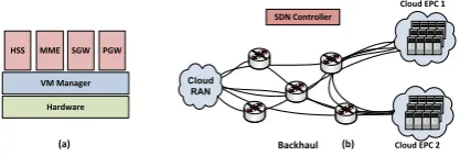
Cloud EPC is composed of all EPC components such as MME, SGW, PGW and HSS. These components still maintain the same standard interfaces between them in order to conform to the 3GPP standard. These components can be composed into a single service function (SF) including MME, SGW and PGW or it can be independent functions. In our case, we assumed that each component is composed into a single function (virtual machine) and this function run on top of dedicated hardware in the cloud platform as shown
in Fig. 4a. The VM manager lies between VMs and
hardware, and acts like a hypervisor between software and hardware.
Hardware VM Manager HSS MME SGW PGW
Cloud EPC 1 SDN Controller
Backhaul Cloud EPC 2
Cloud RAN
(a) (b)
Figure 4. (a) Dedicated hardware running EPC components in
the VMs, (b) Traffic steering between the cloud EPCs using SDN controller during VM images moves between the clouds.
In the cloud platform, it is important to transfer the context of the users or virtual image file from one cloud location to another location for to optimize the
network efficiency and also decrease the load when it
is in overload. In EPC case, there is a need to transfer the active or idle users profile information from a cloud
location to another better location which is near to user
location (see Fig. 4b) (the data transfer can be done
like [33]). For instance, in existing EPC components,
in overload situation it’s very difficult to reduce the
load because of its static behavior of each component. Indeed, the 3GPP also proposed an inappropriate solution on balancing the load between the components
[17]. In the cloud platform, the cloud manager always
track the each virtual machines load. If any function is overloaded, then cloud manager immediately deploys the new virtual machine and moves the active users to newly deployed function. In this case, the active users’ context will transfer from old VM to newly deployed VM without interrupting the active sessions (similar to
[34]). The VM deployment can be at same location or
also another location. However, this depends on the UE location and available resources in the cloud. In fact, the deployment will be near to UE location to reduce the latency.
The SDN controller manages the backhaul network based on information received from the cloud managers
[35]. For instance, if an EPC component image moved
from one cloud center to another cloud center, the
SDN controller dynamically steer active traffic to
the new location using the OpenFlow protocol. The OpenFlow protocol is an initial protocol that applies the SDN concept. It enables a remote software-based controller to manage the connected OpenFlow switches through a well-defined “forwarding instruction set"
[36]. Significantly, the cloud EPC moving from today’s
mostly static deployments to highly dynamic network implementations such as dynamically provisioning and configuration.
3.3. Cloud Manager
The cloud manager can make decisions about the usage of virtual resources. These decision is based on all parameters (i.e. tenant policies, location of users/data centre) and acts towards the carbon copy (cc) to execute them. The cloud manager will configure the SFs during the scaling in/out. For instance, executing SF in the network, the manager will trigger existence of this SF
with other SFs, in order to route the traffic.
The monitoring function in cloud manager will mon-itor and predictions about the bandwidth requested in a certain geographical area at a certain time by an aggregated group of users. Indeed, the manager will be the responsible entity to initial configuration of each SFs including basic networking and configuring of service parameters such as 3GPP LTE/EPC parameters (like identifiers, QoS policies, PCRF parameter, etc).
OPEX. The infrastructure sharing in cloud networks
move the telecom into a completely different network
paradigm, where operators can deploy the network components based on-demand from the tenant, it can be short term or long term sharing. The main players for mobile network sharing are between the operators’ or with the MVNOs.
4.1. Pay As You Go
Infrastructure sharing between operators undoubtedly leads to a reduction of the investment made by each operator involved in the network sharing process. Indeed, present network sharing models are purely static and fixed resources. For instance, the mobile operator (tenant) makes an service level agreement (SLA) with infrastructure owner (i.e. mobile operators owns the infrastructure) for a fixed amount of usage such as bandwidth and fixed time period e.g. for one year. Based on the SLA, the owner designs their network based on the load foreseen in the peak hours. The network design based on custom hardware and
need to be statically provisioned and configured [37].
Consequently, the network architecture does not come any elasticity and on-demand features. For example, the BBUs are deployed in cell site based on peak load and SLA. This deployment is static and custom hardware,
and very difficult to increase the capacity based on
traffic demand. In addition, it’s difficult to optimize
the resource during non-peak hours, this leads to the wastage of resources. These wastages are so costly and it directly influences the OPEX. On the other hand, in existing sharing models, the tenant cannot buy extra resource for a specific time period from the owner due to network static functionality and limited resources. Consequently, the end-user faces a poor QoE during peak hours.
The cloud based mobile network, the operator can share part of the network for specific time periods. For instance, any network equipment failure may occur in the network, let say SGW (serving gateway) in the LTE network. In this case, the operator can demand for a new SGW in a fraction of minutes from the cloud operator and configure with their network, instead of keeping network down for a period of time. After, the failure recovery, the allocated gateway releases and corresponding resource such as CPU and memory can be used for other services. The owner will charged the tenant based on used service resources, versus an entire infrastructure (i.e. the tenant will as he/she used
the resource like Pay-as-you-go [38]). This model will
introduces the new business strategies such as short-term sharing (i.e. an hour based on demand).
4.2. RAN-as-a-Service (RANaaS)
The RANaaS models taps the new business paradigm for mobile operators. In fact, over the decade, the
sharing the access network while maintaining control logic inside the RAN controller of each operator independently of one another. This type of solution can
be difficult to optimize the resource during non-peak
hours, which can be leads to the wastage of resources
([39], [40]). The RANaaS will make it possible to make
an efficient usage of datacenter resources, through the
dynamic deployment of the required resources. Hence, it is possible for a MNOs (cloud service providers) to provide RAN in an on-demand and elastic way.
In RANaaS model, the tenant can be initiate to execute RAN nodes in particular cell site for specific period of time. For instance, due to unexpected events (e.g. football games, public strikes, etc) in particular location, the tenant needs extra resource on those specific locations, in order to avoid congestions/failures in the network. The tenant can demand extra resource (i.e. BBUs and RRUs) for particular cell sites for specific period of time. The owner will initiate the tenant requirement in specified cell site, the cloud manager configure these requirements and execute into the network. For example, the cloud manager will execute new BBUs and RRUs for specific cell site in the cloud and configure these units with the network including networking with tenant core network.
After completion of requirements, provided
resources to tenant will be released and charged for usage of resources and these resources can be used for other services.
4.3. EPC-as-a-Service
The cloudification of the EPC creates the opportunity for the MNOs and MVNOs to move to a completely
different network paradigm, where the network
func-tions that used to be implemented on physical boxes deployed in specific Points of Presence (PoPs), become workloads running on top of a cloud infrastructure.
The cloud service providers (CSP) will provide the EPC entities as a service (i.e. HSS, MME, SGW and PGW as a service), run on a virtualized environment, which is implemented as workloads on a cloud platform (similar to cloud network). For instance, a CSP can integrated the functions by combining services provided by MVNOs and build a specific cloud-based MVNO network in the cloud platform. By this, the MVNO can benefit on low CAPEX and OPEX on their business instead of building their own physical network (i.e. low CAPEX and OPEX for building and maintaining application server, billing units and core equipments, etc.).
5. Analysis of Mobile network investments and
Advantages of sharing models
Mobile operators aggressive pursuit of lean business models has led to an evolution, turning to
Table 1. CAPEX analysis for mobile network [44].
Parameters EstimatedCAPEX (%)
Building, Rigging and Materials 42
eNode B 15
Network Testing 12
Site Acquisition and Design 10
Power 10
Backhaul 6
Spares 3
Router Pricing 2
ever-changing technologies and increasing competition between global and virtual operators, has been pushing mobile operators towards new ways of business strate-gies and low cost network maintenance. Significantly, the saving can be transfer to upgrade their networks and providing better roll out and coverage to end-users.
0 % 10 % 20 % 30 % 40 % 50 % 60 % 70 % 80 %
Active Radio Elements Site Passive Elements Core Network
Figure 5. Mobile network deployment investment
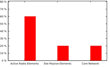
Total deployment investment of mobile network
can be divided as shown in Fig. 5. Here, the
highest investment will be on active elements such as antenna, feeder cable, base station (i.e. eNode B), RAN, transmission system installed in base stations, mobile network equipment, and access node switches, it can be 60% of total investment. The remaining investment on passive elements and core network. The investment on passive elements such as physical sites, buildings,
shelters, towers, power supply, and battery backup [42]
will be 20% and remaining 20% on core network. Table.
1shows an CAPEX on individual elements.
Table.2shows a typical individual OPEX on mobile
network. In emerging and developing countries, this values may varies due to poor infrastructure facilities. In fact, emerging countries has a history of unreliable power supply and frequent cut-outs. African countries less covered by public grid most of the telecom operators depends on diesel generators and solar energy
[43]. Diesel generators cause main disadvantages like
increase the maintenance and transport to the station
Table 2. OPEX analysis for mobile network [19].
Parameters
Estimated OPEX (%)
Network Operations Center (NOC) 17
Field Services 23
Transmission lease management
-Leased Line (LL) fees 12
Network planning and engineering
-ongoing planning 3
Spares and logistics 4
IT infrastructure and application
-applications management 4
3rd party care contracts - HW / SW
maintenance 4
3rd party care contracts - Multi-vendor
repair 1
Other 3rd party contracts - electrical
power and fuel 3
NOC operations TAC2 support 4
Testbed 1
(Ongoing) network optimization 2
Site lease/rental 12
Transmission lease management
-Microwave (MW) frequency fees 2
Site infrastructure management - site
maintenance 4
Site infrastructure management - other
site-related costs for leased sites 0.5
Site infrastructure management - other
site-related costs for owned sites 0.5
Other 3rd party contracts - roaming
management 2
Other 1
especially in rural areas. Significantly, it directly influence on operational expenditures.
Cloud based mobile network sharing between the operators or virtual operators undoubtedly leads to a reduction of the investment and operational
expenditure. Fig. 6 shows the investment saving in
cloud based network. In cloud based network sharing will reduces roughly 50% of total investment. In fact, the operators or MVNOs will rent the resource based on requirement and pay for usage of resources. It is true that, the cloud service provider investment reduction will varies due to building the infrastructure. However, the service provider will benefit from other operators by selling the services, this benefits may overcome the total investments in future. For the clients (other operators/ MVNOs), 50% of total investment on active elements
(total investment shown in Fig. 5) will apparently
access node switches and some RAN elements like BBUs and RRUs, etc. The client can share these elements with cloud provider based on requirement dynamically. Similarly, with the passive and core network elements, in passive element we can benefit more (i.e. 60%) and required less investments. For instance, cloud based sharing no need to invest on building physical site, rents and shelters, etc.
10 % 20 % 30 % 40 % 50 % 60 % 70 % 80 %
Active Elements Passive Elements Core Network Savings
Figure 6. Investment savings in cloud-based mobile network.
In cloud based mobile network, the operational expenditure such as site rental, the fees for leased lines, microwave links, and site infrastructure management represent the site-related costs, electricity and fuel will be reduces roughly 70 - 80%. For example, the client will need less sites, sharing transmission links, installing less equipment and less human investment for management, etc.
6. Implementation and Discussions
Fig.7illustrate the cloud based mobile network testbed
architecture. To provide realistic testbed, we used a software based mobile network entities provided
by Fraunhofer FOKUS OpenEPC [45]. OpenEPC is a
reference implementation of 3GPP’s Evolved Packet Core (EPC) (Releases 11 and 12) developed by the Fraunhofer FOKUS competence center Next Generation Network Infrastructures (NGNI).
Client eNB
EPC Enablers (HSS, PCRF)
Internet
MME
SGW PGW Internet IMS
Gateway
Figure 7. Implemented LTE/EPC architect OpenEPC.
In this emulation, each modules of LTE/EPC such as MME, SGW, PGW, eNB, HSS and UE are running
in each virtual machine. All these VMs are running in single Linux based machine. KVM (Kernel-based Virtual Machine) is used as a hypervisor between
the VMs [46] in kernel. All the VMs are with same
configuration such as 500MB RAM and 20 GB hard drive and each running with Ubuntu 12.04 operating system.
To validate cloud based network, we performed a test to find out the latency of OpenEPC network with compared to direct internet network. We generated
normal IP traffic such as ping traffic between OpenEPC
network and google DNS server (8.8.8.8) and also
Hypertext Transfer Protocol (HTTP) traffic towards
Internet. Similarly, we generated same traffic with
direct Internet access network (i.e. without OpenEPC).
The test results are in Fig. 8. It clearly shows that,
OpenEPC network will have more latency then direct internet access network. This is due to the LTE/EPC network will have an extra IP overhead with GTP tunneling in the user plane nodes (i.e. the tunneling between eNB and SGW, and between SGW and PGW
([47], [48])). When UE generated traffic, the traffic is
tunneled in eNB and forwarded to the SGW. Similarly,
the SGW will tunnel the same traffic and forwarded
to PGW. Due to this encapsulation and decapsulation of GTP tunnels in user plane, the round trip time in LTE/EPC network in increasing compared with direct
internet access network. Interestingly, the IP traffic
latency (see Fig.8a) is more than the HTTP traffic (see
Fig. 8b). However, this latency is totally depends on
the selection of paths and location of servers. In fact, the both the servers are located in same location (i.e.
USA) and they selected the different paths. However,
the latency of LTE/EPC network is around 22ms for IP
traffic and 20ms for HTTP traffic, and these latencies
are acceptable for a audio and video conversation. Based on IMT-2000 performance and Quality of Service requirements, this latency is acceptable (the maximum one-way transfer delay that human perception can
tolerate is 400 ms [49]).
5 10 15 20 25
10 20 30 40 50 60
Thr
oughput (Mbits/sec)
Time (sec)
250k 500k 1000k
10 12 14 16 18 20 22 24
1 2 3 4 5 6 7 8 9 10
A
verage R
ound T
rip T
ime (ms)
OpenEPC Without OpenEPC
(a)IP traffic RTT
5 10 15 20 25
1 2 3 4 5 6 7 8 9 10
A
verage R
ound T
rip T
ime (ms)
OpenEPC Without OpenEPC
(b)HTTP traffic RTT
Figure 8. Average RTT between LTE/EPC network using OpenEPC and direct internet access network.
Fig.10and9depicts the evaluation of throughput in
OpenEPC network. The Fig.10 shows the throughput
evolution in UDP traffic (i.e. can be see as VOIP traffic
which is also an UDP) with respect normal Internet
access network. On the other hand, Fig. 9 shows the
throughput in different TCP window size such as 250k,
500k and 100k. For all this evaluation, we used traffic
generator tool such as Iperf [50], which is able to
generate TCP and UDP traffics with multiple parallel
connections. The Iperf client running in th OpenEPC
UE generates the TCP/UDP traffic towards the server
which is connected to PGW. When increasing the TCP window size the throughput also increases. However, after the saturation state, evenif the incremental in the window size the trhoughput will not increase. Similarly, in the OpenEPC network, above 1000k window size, the throughput is the approximately same. However, this throughput is acceptable for the normal internet connection, which is normally required minimum
1Mbits/sec [51]. In fact, we believe, the same OpenEPC
runs in high volume servers in cloud, the performances are much better and the latency will be reduces to 10ms.
6 8 10 12 14
10 20 30 40 50 60
Thr
oughput (Mbits/sec)
Time (sec)
OpenEPC Case Normal Case
Figure 10. UE throughput for UDP traffic where bandwidth is
limited to 10 Mbits
Similarly, the UDP traffic is generated by the Iperf
client in OpenEPC where bandwidth is limited to 10Mbits/sec. The throughput is around 8.5 average
which is less than the limited bandwidth (in Fig.
10). For better comparison, we evaluated the same
test in normal internet network, where throughput is around 9.5 Mbits/sec which is also less than the limited bandwidth. However, this throughput is acceptable for
the high quality video and VOIP services [51].
This implementation can be a mirror of cloud based mobile network. The main advantages of this cloud based mobile network, the network can be easy scale in/out based on demand and introduces flexibility and elasticity nature to the network. For instance, the VM images OpenEPC of each LTE/EPC nodes can be easily transfer from one data center to other data center and scale in during demand. The VMs migration process is out of scope of this paper. The test results shows, the
latency is acceptable in IP and HTTP traffic case and
also voice and video traffic (which is UDP traffic) is
30ms which is also acceptable then the specifie time (i.e. end-to-end 150ms, including access network) using this cloud based network.
7. Challenges
The cloud based mobile network sharing imposes some technical challenges for operators.
• The major challenges in the cloud RAN are to decrease the bandwidth usage between the antenna and the BBU in order to carry baseband signaling. For example, it requires 10 Gpbs transmission rate to run a eight antenna LTE with
20 MHz [24]. On the other hand, centralizing the
BBUs and distributing the radio heads require a ubiquitous fiber network which is a cost
effective solution. It can be solved by using
microwave links for small configurations (low number of antenna, 5 or 10MHz spectrum, and small distances) thanks to millimetrics waves bandwidth
a challenge for the cloud provider. In addition, scaling up/down VMs and configuring them with other VMs may cause performance issues like latency. For instance, when a MME scale ups, it has to wait until all the interfaces are established with other VMs such as S11, S1-MME, S6a. On the other hand, the load balancing between the VMs is another technical challenge. For example, when VMs scale up/down, the active
traffic balancing with other VMs and tunnels
encapsulation/decapsulation, etc. However, it can be possible to reuse an existing load balancer in data centers with extension to mobile network.
• In the sharing network, billing models and implement these models are challenging issues. For instance, each tenant (MNOs and MVNOs) will have their own SLAs with their users and also with cloud provider. In this case, all these SLAs as to be implemented in the network and real-time monitoring is needed. On the other hand, each tenant requires interfaces to monitor their resources and implement any new service into the network. However, this can be solved by providing interfaces with control platform but the cloud provider has to take care of viewing and managing tenant user profile only.
8. Conclusion and Perspectives
Infrastructure sharing offers compelling cost benefits to
mobile operators and is therefore expected to become a major solution for future deployments. In this paper, we proposed a cloud based mobile network sharing model for LTE/EPC architecture. We believe this model shifts the network into new paradigm while opening up a range of new business models through which the mobile operators can increase the revenue and providing guarantee QoS for the end users. In addition, in this paper, we presented the total network sharing including the core network between the MNOs and MVNOs with low investments. This proposal is the first step towards a future cloud based mobile network and the next step of this work to be implement the total proposed architecture in the orange cloud and validate the sharing models and their functions.
This work has many perspectives. Firstly, to test the performance of OpenEPC in the cloud network. In addition, also need to develop an SDN controller to manage the back-haul network based on commands received from the cloud managers. Then, need to develop an new algorithms in the cloud manager and SDN controller in order to act dynamically based the VMs characteristics and also to increase the network performances. Finally, our proposal will be extended to non-3GPP access like WiFi which are connected to PGW via ePDG.
References
[1] Téhomas W.-H., “Allocating Radio Spectrum for the Mobile Data Tsunami", Engage Volume 13, Issue 2, July 2012.
[2] Carrier-Grade Virtualization for
Tele-com Service Providers, https://
solutionexchange.vmware.com/store/content/
carrier-grade-virtualization-for-telecom-\ service-providers.
[3] Taleb, T.; Ksentini, A, “Follow me cloud: interworking federated clouds and distributed mobile networks," IEEE Network , vol.27, no.5, pp.12,19, September-October 2013.
[4] Tellabs “End of profit" study executive summary, White
Paper, 2011. http://www.tellabs.com/markets/tlab_
end-of-profit_study.pdf.
[5] Cisco white paper on mobile data traffic, “Cisco Visual
Networking Index: Global Mobile Data Traffic Forecast
Update 2012-17", 6 Feb 2013.
[6] GSMA Intelligence. https://gsmaintelligence.com/
analysis/2011/03/european-mobile-arpu-falls-20/
270/
[7] “Telecoms in emerging markets", straighttalk, Ovum, February 2009
[8] Tarik Taleb, Peer Hasselmeyer, and Faisal Ghias Mir, “Follow-Me Cloud: An OpenFlow-Based Implementa-tion". In Proceedings of the 2013 IEEE International Con-ference on Green Computing and Communications and IEEE Internet of Things and IEEE Cyber, Physical and Social Computing Washington, DC, USA, 240-245. [9] Taleb, T.; Ksentini, A, "An analytical model for Follow Me
Cloud," 2013 IEEE Global Communications Conference (GLOBECOM), vol., no., pp.1291,1296, 9-13 Dec. 2013. [10] Yasir Zaki, Liang Zhao, Carmelita Goerg, and Andreas
Timm-Giel, “LTE mobile network virtualization", Journal Mobile Networks and Applications, August 2011. [11] Venmani Philip and Yvon Gourhant and Djamal
Zeghlache,“OpenFlow as an Architecture for e-Node B Virtualization", 2012 third International e-Infrastructure and e-Services for Developing Countries.
[12] Network Functions Virtualisation, An Introduction, Ben-efits, Enablers, Challenges & Call for Action, Introductory White Paper, October 22-24, 2012.
[13] ONF Wireless & Mobile Working group, Open Network-ing Foundation (ONF).
[14] Meddour, D.-E., Rasheed, T., & Gourhant, Y., “On the Role of Infrastructure sharing for Mobile Network Oper-ators in Emerging Markets", The International Journal of Computer and Telecommunications Networking, Volume 55, Issue 7, 2011.
[15] Digital World Forum, “Low cost broadband access and
infrastrucure", http://digitalworld.ercim.eu/wp3.
html
[16] Patil, Sunil D., “Challenges in Outsourcing of Telecom Tower Management - System Integrators (SI) Perspective", Social Science Research Network (SSRN), December 18, 2012.
[18] Suzanne, C., “AT&T and T-Mobile network sharing for those in Sandy’s path", NBC News, Oct. 31, 2012.
[19] Frisanco, T.; Tafertshofer, P.; Lurin, P.; Ang, R., “Infrastructure sharing and shared operations for mobile network operators From a deployment and operations view", IEEE NOMS Network Operations and Management Symposium, vol., no., pp.129,136, 7-11 April 2008 [20] Victor, F.; Chris, D.; Alphonse, R.; Shohinee, G., “Tower
sharing in the Middle East and Africa: Collaborating in competition", The Delta Perspective, April 2009
[21] Berge Ayvazian., “Market Opportunities for B2C Fourth - Generation MVNOs", Heavy reading white paper, Oct 2012
[22] Copeland, R.; Crespi, N., “Modelling multi-MNO business for MVNOs in their evolution to LTE, VoLTE & advanced policy", 2011 15th International Conference on Intelligence in Next Generation Networks (ICIN) , pp.295,300, 4-7 Oct. 2011
[23] ABI Research, “SDN and Virtualization of Evolved
Packet Core to be a $400 Million Market by
2018" https://www.abiresearch.com/press/
sdn-and-virtualization-of-evolved-packet-core-to-b
[24] China Mobile,“C-RAN The Road Towards Green RAN", White Paper, China Mobile Research Institute, Oct 2011. [25] Michelle Donegan, “China Mobile Steps Up Cloud RAN
Efforts", European Editor, Light Reading Mobile, Mar
2012.
[26] Clark, Christopher and Fraser, Keir and Hand, Steven and Hansen, Jacob Gorm and Jul, Eric and Limpach, Christian and Pratt, Ian and Warfield, Andrew., “Live Migration of Virtual Machines", Proceedings of the 2nd Conference on Symposium on Networked Systems Design & Implementation - Volume 2, 2005
[27] Kimio, W.; Mamoru, M., “Outdoor LTE Infrastructure Equipment (eNodeB)", FUJITSU Sci. Tech. J., Vol. 48, No. 1, pp. 27-32, January 2012.
[28] Common Public Radio Interface (CPRI); Interface Specification, V4.2, Sept 2010.
[29] Namba, S.; Warabino, T.; Kaneko, S., “BBU-RRH switch-ing schemes for centralized RAN", 7th International ICST Conference on Communications and Networking in China (CHINACOM), vol., no., pp.762,766, 8-10 Aug. 2012
[30] Sabella, D.; Rost, P.; Yingli Sheng; Pateromichelakis, E.; Salim, U.; Guitton-Ouhamou, P.; Di Girolamo, M.; Giuliani, G., “RAN as a service: Challenges of designing a flexible RAN architecture in a cloud-based heterogeneous mobile network," Future Network and Mobile Summit (FutureNetworkSummit), 2013 , vol., no., pp.1,8, 3-5 July 2013.
[31] Software defined radio. http://en.wikipedia.org/
wiki/Software-defined_radio
[32] Sama, M.R.; Gupta, A.; Afifi, H.; Genet, M.G.; Jouaber, B., “Energy saving by Base Station pooling: A signaling framework", IFIP Wireless Days (WD), vol., no., pp.1,7, 21-23 Nov. 2012
[33] Duong, Hoa Hà and Demeure, Isabelle, “Data Sharing over Mobile Ad Hoc Networks", Proceedings of the
8th International Conference on New Technologies in Distributed Systems, USA, 2008.
[34] Liu, Ziyang and Hacigümüs, Hakan, “Online Optimiza-tion and Fair Costing for Dynamic Data Sharing in a Cloud Data Market", Proceedings of the 2014 ACM SIG-MOD International Conference on Management of Data, USA, 2014.
[35] Staessens, D.; Sharma, S.; Colle, D.; Pickavet, M.; Demeester, P., “Software defined networking: Meeting carrier grade requirements," 18th IEEE Workshop on Local & Metropolitan Area Networks (LANMAN), vol., no., pp.1,6, 13-14 Oct. 2011
[36] Open Networking Foundation, OpenFlow Switch Speci-fication, Version 1.3.1, 6 Sept 2012.
[37] Jain, R.; Paul, S., “Network virtualization and software defined networking for cloud computing: a survey," IEEE Communications Magazine, vol.51, no.11, pp.24,31, November 2013
[38] Ibrahim, S.; Bingsheng He; Hai Jin, "Towards Pay-As-You-Consume Cloud Computing," IEEE International Conference on Services Computing (SCC) , vol., no., pp.370,377, 4-9 July 2011.
[39] NGMN report, “Suggestions on Potential Solutions to C-RAN", Technical Report, the Next Generation Mobile Networks (NGMN) Alliance, Jan, 2013.
[40] F. Loizillon et. al. “Final results on seamless mobile IP service provision economics", TONIC project deliverable, October 2002.
[41] Passive Infrastructure Sharing in Telecommunications, KPMG Africa Limited, 2011.
[42] Tom, L.; Peter, E.; Michael, R., “Passive infrastructure sharing", Allen & Overy, white paper, 2012.
[43] “Power to the base stations - a modest proposition", http://www.balancingact-africa.com/news/en/issue-no-361/top-story/power-to-the-base-st/en
[44] Market Research Report: Emerging Market Opportuni-ties, Analysis Mason, May 2010.
[45] “OpenEPC - Open Evolved Packet Core", Fraunhofer FOKUS. http://www.openepc.net/index.html
[46] “Kernel-based Virtual Machine",
http://en.wikipedia.org/wiki/Kernel-based_Virtual_Machine
[47] “3GPP TS 29.274 Technical Specification Group Core Network and Terminals; 3GPP Evolved Packet System (EPS); Evolved General Packet Radio Service (GPRS) Tunnelling Protocol for Control plane (GTPv2-C); Stage 3, (Release 11), 2012-09".
[48] “3GPP TS 29.281 Technical Specification Group Core Network and Terminals; General Packet Radio System (GPRS) Tunnelling Protocol User Plane (GTPv1-U), (Release 9), 2010-06".
[49] Pierre, L.; Thierry, L., “Evolved Packet System (EPS) -The LTE and SAE Evolution of 3G UMTS", In John Wiley & Sons Ltd, France, 2008.
[50] Iperf,https://iperf.fr/