GSJ: Volume 6, Issue 6, June 2018, Online: ISSN 2320-9186
www.globalscientificjournal.com
D
ESIGN AND
C
ONSTRUCTION OF
R
EMOTE
C
ONTROL
A
UTOMATIC
M
AINS
F
AILURE
(AMF)
S
WITCH
D. C. Idoniboyeobu
1, B. A. Wokoma
2and O. S. Olaleye
3 1,2&3(Department of Electrical Engineering, Rivers State University, Nigeria)
ABSTRACT:
The need for continuous power supply and its reliability has increased rapidly over the years as most human activities solely depend on electricity, especially in some areas where uninterrupted power supply is a must. Interruption of power supply has adverse effects on the consumers of the electricity and consequently their equipment are liable to damage, with operations and processes halted as commonly noticed in developing countries like Nigeria. In this paper, a remote control automatic mains failure switch is designed and constructed for a 3-phase, 4-wire electrical/electronic equipment. It provides a switching mechanism that transfers the consumer loads from utility supply to a power source from a generator in the event of power failure in the utility/public mains supply. Phase detectors were used to monitor the lines of the mains supply and a relay based system was used to actualize the control actions. The remote control unit integrated into the system ensures savings of an average of 12% unnecessary expense monthly from non-critical use of generator as it allows the generator to be switched on remotely when occasioned with the absence of any or all of the phases in the public mains supply. In addition to this, it ensures continuous supply to the loads with operators having the ability to exert control the supply system at any time from a distance of 100 meters.I.
INTRODUCTION
Delicate electrical real-time processes and operations are power dependent. Unplanned, unexpected power outages in these operations could cause injuries, fatalities, serious business disruptions, data and financial losses. Activities that may suffer great impact on occasion of power outage include medical surgeries, computer data-centre operations, oil-well data caching, mission critical processes and so forth.
For instance, if during a caesarean operation, the Power Holding Company of Nigeria (PHCN) which is the organization responsible for power utility supply cuts power as a result of any disruption in the power supply system, we all know that both the mother and the baby’s life can be jeopardized and death may result. In oil industries, like in seismic data processing, any abrupt electrical power outage will incur a high magnitude data loss and eventual colossal economic loss [1].
In Nigeria, and as well as in many other developing countries of the world, public electricity supply is very erratic, unpredictable and unreliable, [2].This project sets to remove the cost of running the generator when not so critically necessary by integrating remote control unit into an advanced seamless, automatic mains failure (AMF) that switches electrical supply from public electricity to generator and vice versa.
II.
R
ELATEDW
ORKSR
ecently there have being related works where actualization of automatic mains failure (AMF) system had been recorded. Some relate works but not limited to those listed are reviewed below:
In the paper presented in [3] like others in which the AMF is automated using a relay mechanism; the authors used a phase failure detector (PFD) to monitor the power supply system via a relay unit which gives signal to an air circuit breaker (ACB) to be either activated or to be inactivated due to thepresence of the prescribed voltage level of the supply. A delay was then introduced in the system design to prevent transient fault conditions.
Some AMF systems are automated using programmable logic controllers (PLCs) or others associated electronic integrated circuits (ICs) as seen in [4], [5] and other literatures. The PLCs are used for programming the control actions of the AMF systems. For those AMF systems that uses ICs; the ICs are used for timing purposes and a relay mechanism is still used to actualize the switching action.III.
M
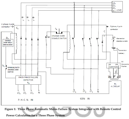
ETHODOLOGYA remote control automatic mains failure (AMF) switch was designed and constructed for a three-phase four-wire public utility mains and a three-phase four-wire generator. This was achieved by using majorly: a three-phase failure detector, two three-phase four-pole contactors, a normally-closed, timed-open (NCTO) relay, an AC relay, a receiver, a transmitter, a 12V battery and others. The three-phase failure detector was used as the first input point for the public utility mains in order to detect the outage of any or two or all of the three phases of the public supply. Immediately connected to the output of this three phase failure detector was a three-phase, four-pole contactor having a normally-closed contact which opens upon energization whenever all the three phases of public utility mains are available. At this instance, it powers up the three-phase four-wire connected load. This first contactor also supplies voltage to the coil of the second three-phase, four-pole contactor at the generator output end. The second three-phase four-pole contactor stays de-energized once there is public utility supply and separates the generator output from the consumer load thus avoiding a clash of the two power supplies.
Figure 1: Three Phase Automatic Mains Failure System Integrated with Remote Control
3.1 Power Calculation for a Three Phase System
Using a generating set of 6KVA, operating at 50Hz frequency and a power factor of 0.9 on a 220V/415V, the contactor rating and cable ratings are determined as follows:
3.1.1 The Contactor Rating
From the above description of the system, we have:
Apparent power (S) = 6 x 10³ VA (6KVA) (1a) Line voltage (VL) = 415V (1b) Phase voltage (VP) = 220V (1c)
Active power (P) = Apparent power x Power factor (2) = 6KVA x 0.9
= 5.4KW
Now,
Assuming a balanced load is being used,
= 9.1 Amps (3b)
The contactor required will have a minimum current rating of 9.1 Amps
For increased efficiency, a tolerance of about +25% is recommended by IEEE Regulation.
Thus, contactor rating will be,
= 9.1 + (4)
= 9.1 + 2.275
= 11.375 Amps
3.1.2 The Cable Rating
Current per phase (IP) = 9.1 Amps
Thus, any cable used should be capable of carrying about 1½ times the phasor current according to IEEE
Regulation.
Therefore, required cable should withstand a current of at least
= 9.1 + (50% x 9.1) (5)
= 9.1 + 4.55
= 13.65 Amps
IV.
R
ESULTS ANDD
ISCUSSIONSGenerator starting test was implemented to ensure that the generator can be started automatically when public mains supply fails. Then, the voltage variation test was carried out to be sure that the supply voltage is within permissible limit i.e. 240V +/- 5%. The remote control unit was tested to ascertain that the generator can be switched off without any issue when there is no critical need for electrical power supply despite the unavailability of public utility. Additionally, the remote control unit test was effected to ensure that the generator can also be started remotely when there comes up an urgent need for electrical power supply and public mains supply is still unavailable. Finally, a comprehensive testing of the entire automatic mains failure switch was carried out to ensure the constructed circuit is capable of ensuring a seamless switching of electrical power to the connected load whenever public mains supply fails and whenever it returns.
4.1 Phase Failure Detection Test
I. The 3-phase, 4-pole contactor C1 was isolated. II. The delay switch was isolated.
III. Direct public utility 3-phase, 4-wire supply was fed into the phase failure detector P1.
IV. The output from the phase failure detector was then used to power on a 3-phase halogen lamp.
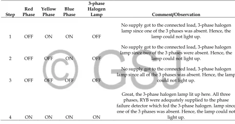
As rightly tabulated in Table 4.1, Step 1 showed phases Y and B supplied into the phase failure detector, but with the simulated absence (not fed) of the R phase. This resulted into the halogen lamp being OFF.
Step 2 showed the outages of R and Y phases, with only the Blue phase present which eventually caused the halogen lamp not coming ON.
Step 3 depicted the unavailability of al the 3 phases which ultimately brought about the halogen lamp not ON.
However, Step 4 presented the full supply of all the three phases R, Y and B phases which then resulted into an output supply which powered ON the halogen lamp.
Table 4.1 Results from Phase Failure Detection Tests
Step Phase Red Yellow Phase Phase Blue
3-phase Halogen
Lamp Comment/Observation
1 OFF ON ON OFF
No supply got to the connected load, 3-phase halogen lamp since one of the 3 phases was absent. Hence, the
lamp could not light up.
2 OFF OFF ON OFF
No supply got to the connected load, 3-phase halogen lamp since two of the 3 phases were absent. Hence, the
lamp could not light up.
3 OFF OFF OFF OFF
No supply got to the connected load, 3-phase halogen lamp since all of the 3 phases was absent. Hence, the lamp
could not light up.
4 ON ON ON ON
Great, the 3-phase halogen lamp lit up here. All three phases, RYB were adequately supplied to the phase failure detector which fed the 3-phase halogen. lamp since one of the 3 phases was absent. Hence, the lamp could not
light up.
4.2 Relay Switching Test
Another test carried-out was on the relay switching test which was done to ensure the relays can switch back to generator when the public utility power is out and vice-versa. Test was conducted to ascertain the workability of the remote control using the components below:
I. A 12V AC adapter II. A 2W bulb III. Receiver (Rx) IV. Transmitter (Tx)
4.3 Changeover Disable Switch Test
Diligent test was carried out to ascertain the workability of the changeover disable switch with the following actions:
All the three phases from the generator were connected to the manual switch S2 which was has 4-leg push-button switch being a phase switch; and connected the push-button switch S2 output to a 3-phase halogen lamp.
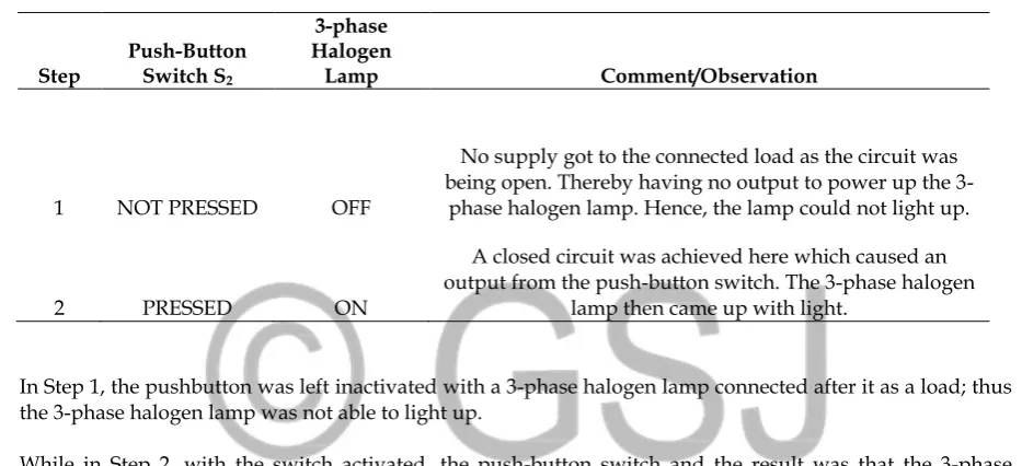
Basically, a 3-phase push-button switch is opened when its button is not pressed which results in no output from it. Therefore, in order to simulate a scenario of the generator supply not being fed into the connected load when public utility is available; the following steps were followed as captured in Table 4.2.
Table 4.2 Results from Changeover Disable Switch Test
Step Push-Button Switch S2
3-phase Halogen
Lamp Comment/Observation
1 NOT PRESSED OFF
No supply got to the connected load as the circuit was being open. Thereby having no output to power up the
3-phase halogen lamp. Hence, the lamp could not light up.
2 PRESSED ON
A closed circuit was achieved here which caused an output from the push-button switch. The 3-phase halogen
lamp then came up with light.
In Step 1, the pushbutton was left inactivated with a 3-phase halogen lamp connected after it as a load; thus the 3-phase halogen lamp was not able to light up.
While in Step 2, with the switch activated, the push-button switch and the result was that the 3-phase halogen lamp came ON.
4.4 Remote Control Test
In order to ensure the designed and constructed remote control automatic mains failure switch achieves its objectives and functions, several tests were carried out on this project which ranges from phase failure detection test, change over delaytest, changeover disable switch test, generator starting test, remote control test to mains failure test.The phase failure detection test was implemented to ensure that if there is any problem (over-voltage, brownout or outage) in any/all of the public utility three phases, the phase failure detector is able to detect the issue and cut off supply to the load.Next, the change-over delay test was done to ascertain that upon the return of public mains supply the generator does not immediately switch off supply to the load and switch off itself without allowing a delay of 5 seconds for stability to be achieved.Changeover disable switch test was also conducted to ensure that there is no switching of load to the generator when public mains supply fails, most especially when the generator is under maintenance or being steamed.
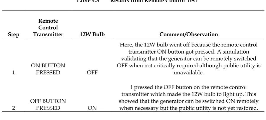
Table 4.3 Results from Remote Control Test
Step
Remote Control
Transmitter 12W Bulb Comment/Observation
1 ON BUTTON PRESSED OFF
Here, the 12W bulb went off because the remote control transmitter ON button got pressed. A simulation validating that the generator can be remotely switched OFF when not critically required although public utility is
unavailable.
2
OFF BUTTON
PRESSED ON
I pressed the OFF button on the remote control transmitter which made the 12W bulb to light up. This showed that the generator can be switched ON remotely
when necessary but the public utility is not yet restored.
4.5 Changeover Delay Test
The changeover delay mechanism was employed to ensure that the public mains power becomes stable before the generator switches off and connected load gets transferred to public utility power. A normally-closed, timed-open (NCTO) contact relay was used for the delay mechanism. This type of contact is normally closed when the coil is unpowered (de-energized). The contact is opened with the application of power to the relay coil, but only after the coil has been continuously powered for the specified amount of time. In other words, the direction of the contact’s motion (either to close or to open) is identical to a regular NC contact, but there is a delay in the opening direction. Although the delay occurs in the direction of coil energization, this type of contact is alternatively known as a normally-closed, on-delay: Below in Table 4.4 were the actions carried out to for its testing were summarized.
A 12W bulb was connected to the output terminals of the NCTO relay and observed its performance when the time was 1 second, 2 seconds, 3 seconds, 4 seconds and 5 seconds. Diligently observing the status of the 12W lamp at 1 second, it was noticed that there was no light from the bulb. At 2 seconds, no light. At 3 seconds, no illumination either. Up to the 4th second, the 12W bulb was not powered ON. All these were obvious because the NCTO relay remained closed as its pre-set time was not reached and hence no output from it to power on the 12W bulb. However, at 5 seconds which was the pre-set delay time, there was a sparkling illumination from the 12W bulb. This simply was so because the coil inside the NCTO relay had been consecutively powered for 5-second duration and thereby forced opened to release power which ultimately powered ON the 12W bulb.
Table 4.4 Results from Changeover Delay Test
Time Delay
Relay 12W Bulb Comment/Observation
time=1 sec OFF
The 12W bulb could not light up because there was no output from the time delay relay as the pre-set time of 5 seconds was not yet reached. Thus, the normally-closed timed-open (NCTO) contact relay
failed to open for any output to power up the 12W bulb. time=2 secs OFF
time=3 secs OFF time=4 secs OFF
4.6 Generator Starting Test
The generator ability to automatically startup immediately there is a failure of the public utility mains power was one of the major objectives of this work. Its testing was carried-out to overwhelmingly ascertain this using the following components:
I. 240V AC Relay RL
II. 6 KVA, 3-phase 4-wire Generator III. 24V DC Battery
As summarized in Table 4.5, a 2-count step tests were carried-out as follows:
In Step 1, the AC Relay was powered with the utility power supply which caused its coil to be energized thereby not making any electrical connection with the starting point of the 6 KVA 3-phase 4-wire generator; as a result of this, the connected load of 3-phase 4-wire could not be powered on.
A contrast however existed in Step 2, were the electrical socket mains to the relay were switched off. The relay got de-energized and eventually switched ON the generator which ultimately got the 3-phase halogen lamp to glow.
Table 4.5 Results from Generator Starting Test
Step
AC Relay RL
3-phase 4-wire Generator
3-phase Halogen
Lamp Comment/Observation
1 energized OFF OFF
Here, the 3-phase halogen lamp remained off because the AC Relay RL was being energized by the AC supply from public utility power. This simulated that the generator remained OFF and cannot automatically
start.
2
de-energized ON ON
The generator got triggered and started by the AC Relay de-energization and ultimately powered up the
3-phase halogen lamp. Thereby evidenced that the generator can automatically start up once the public
mains power fails.
V.
C
ONCLUSIONREFERENCES
[1]. A. F. Agbetuyi, A. A. Adewale, J. O. Ogunluyi, & D. S. Ogunleye, “Design and Construction of an Automatic Transfer Switch for a Single Phase Power Generator”. Department of Electrical and Information Engineering, Covenant University, Ota, Nigeria: retrieved on April. 2015.
[2]. C. A. Osaretin, E. I. Ibhadode & S. O. Igbinovia, “Design and Implementation of Automatic Changeover Switch (With Step Loading) for Renewable Energy Systems”. International Journal of Renewable Energy & Environment, vol. 2, pp. 179-192, 2016.
[3]. D. Ajit, P. Mohsin, M. Prashant & K. Vijaykumar, “Design and Development of Automatic Mains Failure Panel for Diesel Generator”. International Journal of Engineering Research and General Science (IJERGS), vol. 4, no. 2, pp. 458-464, 2016.
[4]. J. G. Kolo, “Design and Construction of an Automatic Power Changeover Switch”. Assumption University Journal of Technology, vol. 11, no. 2, pp. 1-6, 2007.
[5]. R. V. Pandya, R. N. Ramoliya, B. D. Pandit & D. A. Gavadiya, “Automatic Changeover of Generator for Power Supply”. International Journal for Scientific Research & Development (IJSRD), vol. 5, no. 1, pp. 1348-1350, 2017.
[6]. C. C. Obasi, B. O. Olufemi, J. A. John, O. V. Ibiam & C. O. Ubadike, “Design and Implementation of Microcontroller Based Programmable Power Changeover”. Computer Engineering and Intelligent Systems, vol.6, no.12, pp. 51-56, 2015.